Page 1426 of 2893

A
B
C
Except Type S model:
07GAF-SE00100
Type S model:
07GAF-SD40100
C Press
D D
A
B C
Except")
����
����
Wheel Bearing Replacement
18-18Front Suspension
Knuckle/Hub/Wheel Bearing Replacement (cont’d)
A
B
C
Except Type S model:
07GAF-SE00100
Type S model:
07GAF-SD40100
C Press
D D
A
B C
Except Type S model:
07GAF-SE00100
Type S model:
07GAF-SD40100
Press
17. Install the knuckle/hub in the reverse order of
removal, and note these items:
First install all of the components, and lightly tighten the bolts and the nuts, then raise the
suspension to load it with the vehicle’s weight
before fully tightening to the specified torque
values.
Be careful not to damage the ball joint boot when connecting the knuckle.
Before connecting the lower ball joint to the knuckle, degrease the threaded section and the
tapered portion of the ball joint pin, the ball joint
connecting hole, the threaded section, and the
mating surfaces of the castle nut.
Torque the castle nut to the lower torque specification, then tighten it only far enough to
align the slot with the ball joint pin hole. Do not
align the castle nut by loosening it.
Use a new spindle nut during reassembly.
Before installing the spindle nut, apply a small amount of engine oil to the seating surface of the
nut. After tightening, use a drift to stake the
spindle nut shoulder against the driveshaft.
Before installing the brake disc, clean the mating surfaces of the front hub and the inside of the
brake disc.
Before installing the wheel, clean the mating surfaces of the brake disc and the inside of the
wheel.
18. Check the wheel alignment, and adjust it if necessary (see page 18-5). 1. Separate the hub (A) from the knuckle (B) using the
hub dis/assembly tool and a hydraulic press. Hold
the knuckle with the attachment (C) of the hydraulic
press or equivalent tool. Be careful not to damage
or deform the splash guard (D). Hold onto the hub
to keep it from falling when pressed clear.
2. Press the wheel bearing inner race (A) off of the hub (B) using the hub dis/assembly tool, a
commercially available bearing separator (C), and a
press.
08/08/21 14:56:51 61SNR030_180_0018
ProCarManuals.com
DYNOMITE -2009-
Page 1427 of 2893
 and the snap ring (B)
from the knuckle (C).")
�
��
�
�������
18-19
5x0.8mmA
B C
A 07749-0010000
B Press
07746-0010500 B
E
Press
07965-SD90100
A C D
07GAD-SD40101 INSIDE
3. Remove the splash guard (A) and the snap ring (B)
from the knuckle (C).
4. Press the wheel bearing (A) out of the knuckle (B) using the attachment, the driver handle, and a
press. 5. Wash the knuckle and the hub thoroughly in high
flash point solvent before reassembly.
6. Press a new wheel bearing (A) into the knuckle (B) using the old bearing (C), a steel plate (D), the
attachment, the support base, and a press.
NOTE: Install the wheel bearing with the wheel speed sensor magnetic encoder (E) (brown color)
toward the inside of the knuckle.
Remove any oil, grease, dust, metal debris, and other foreign material from the encoder surface.
Keep all magnetic tools away from the encoder surface.
Be careful not to damage the encoder surface when you insert the wheel bearing.
(cont’d)
08/08/21 14:56:52 61SNR030_180_0019
ProCarManuals.com
DYNOMITE -2009-
Page 1434 of 2893

A
B
Press
07AAF-SVAA100
07AAF-SVAA200
(Attachment A) B
A
Press
07AAF-SVAA100
07AAF-SVAA200
(A")
����
��������
����
�
Bushing Replacement
18-24Front Suspension
Lower Arm Removal/Installation (cont’d)
A
B
Press
07AAF-SVAA100
07AAF-SVAA200
(Attachment A) B
A
Press
07AAF-SVAA100
07AAF-SVAA200
(Attachment B)
B
07AAF-SVAA200
(Attachment A)
C
21°20’ 3°
A
FRONT
A
B
CNOTE: Replace the lower arm (A) as an assembly if the
lower arm has the paint mark (B) around the hole near
the front bushing. The paint mark can also be seen
around a hole on the bottom side of the lower arm in
the same area. Paint marks indicate a oversize bushing
has been installed.
1. Press out the bushing (A) with the bushing driver, receiver set (attachment A), and a hydraulic press,
and remove the bushing from the lower arm (B).
NOTE: Be careful not to damage the inside of the
bushing hole when pressing on the bushing.
2. Clean the mating surfaces of the new bushing and the lower arm. 3. Position the tab (A) of the bushing (B) with the
lower arm (C) as shown.
4. Using a hydraulic press, bushing driver, and receiver set (attachments A and B), press in the
bushing into the lower arm.
5. Using a yellow oil-based paint marker, paint a mark (A) around the hole (B) near the front bushing (C).
Also paint a mark around the hole on the bottom
side of the lower arm in the same area.
NOTE: These marks are used to identify a lower
arm that has had the bushing replaced. Do not
replace the bushing in a lower arm with there paint
marks; you must replace the lower arm.
08/08/21 14:57:37 61SNR030_180_0024
ProCarManuals.com
DYNOMITE -2009-
Page 1438 of 2893
����
�(�#�'�����������������������
���
���
�"�����)����
Exploded View
18-28Front Suspension
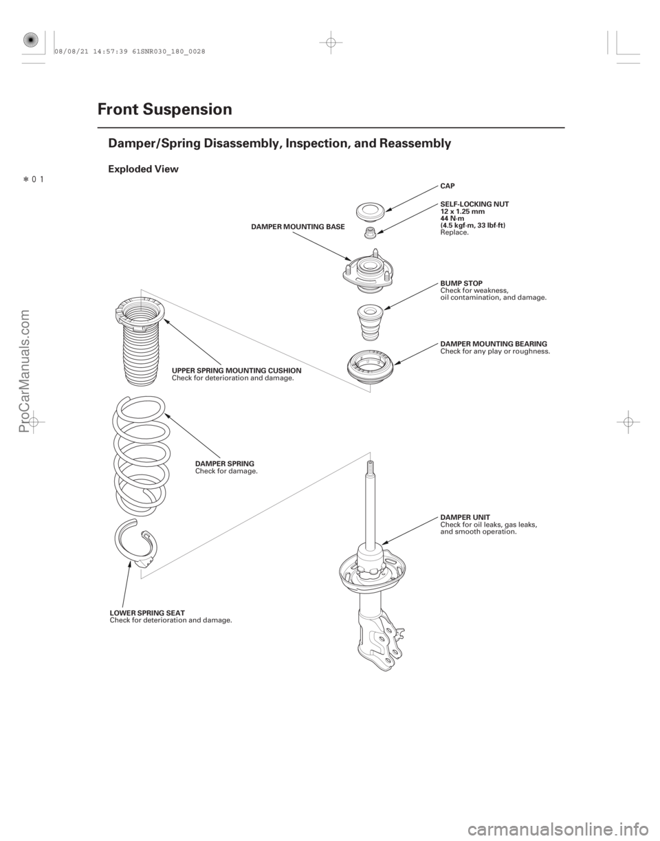
Damper/Spring Disassembly, Inspection, and Reassembly
DAMPER MOUNTING BEARING
BUMP STOP
DAMPER UNIT CAP
SELF-LOCKING NUT
12x1.25mm
44 N·m
(4.5 kgf·m, 33 lbf·ft)
UPPER SPRING MOUNTING CUSHION DAMPER SPRING DAMPER MOUNTING BASE
LOWER SPRING SEAT Check for any play or roughness.
Check for weakness,
oil contamination, and damage.
Check for oil leaks, gas leaks,
andsmoothoperation. Replace.
Check for deterioration and damage. Check for damage.
Check for deterioration and damage.
08/08/21 14:57:39 61SNR030_180_0028
ProCarManuals.com
DYNOMITE -2009-
Page 1439 of 2893

����
����� ����
Special Tools Required
Disassembly
Inspection
18-29
A
A
12x1.25mm
07AAA-SVAA100
B
Strut nut adapter 07AAA-SVAA100
NOTE: When compressing the damper spring, use a
commercially available strut spring compressor
(Branick MST-580A or Model 7200, or equivalent)
according to the manufacturer’s instructions.
1. Remove the cap (A) from the top of the damper.
2. Compress the damper spring, then remove the self- locking nut (A) using the strut nut adapter, a ratchet
or breaker bar while holding the damper shaft with
a hex wrench (B). Do not compress the spring more
than necessary to remove the nut.
3. Release the pressure from the strut spring compressor, then disassemble the damper as
shown in the Exploded View. 1. Reassemble the damper mounting base and the
self-locking nut.
2. Compress the damper assembly by hand, and check for smooth operation through a full stroke,
both compression and extension. The damper
should extend smoothly and constantly when
compression is released. If it does not, the gas is
leaking, and the damper should be replaced.
3. Check for oil leaks, abnormal noises, or binding during these tests.
(cont’d)
Replace.
08/08/21 14:57:40 61SNR030_180_0029
ProCarManuals.com
DYNOMITE -2009-
Page 1450 of 2893
���
�(�#�'���������������
�������
���
����� �����)����
Exploded View
18-39
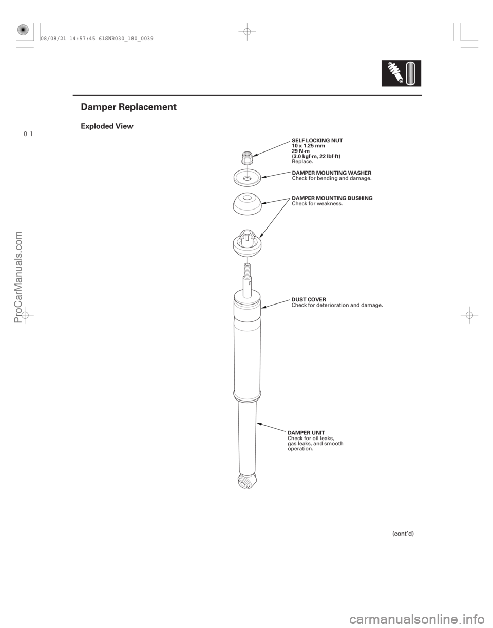
Damper Replacement
SELF LOCKING NUT
10x1.25mm
29 N·m
(3.0 kgf·m, 22 lbf·ft)DAMPER MOUNTING WASHER
DAMPER MOUNTING BUSHING
DAMPER UNIT DUST COVER
(cont’d)
Replace.
Check for bending and damage.
Check for weakness.
Check for oil leaks,
gas leaks, and smooth
operation. Check for deterioration and damage.
08/08/21 14:57:45 61SNR030_180_0039
ProCarManuals.com
DYNOMITE -2009-
Page 1452 of 2893

Type S model:
12x1.25mm
69 N·m (7.0 kgf·m, 51 lbf·ft)
1. Push on the damper as shown")
��������
���
InspectionInstallation
18-41
A
B
A
Except Type S model:
12x1.25mm
59 N·m (6.0 kgf·m, 43 lbf·ft)
Type S model:
12x1.25mm
69 N·m (7.0 kgf·m, 51 lbf·ft)
1. Push on the damper as shown.
2. Compress the damper assembly by hand, and check for smooth operation through a full stroke,
both compression and extension. The damper
should extend smoothly and constantly when
compression is released. If it does not, the gas is
leaking and the damper should be replaced.
3. Check for oil leaks, abnormal noises, or binding during these tests. 1. Install the damper mounting bushing (A) onto the
damper unit. Position the damper assembly (B)
between the body and tra iling arm.
NOTE: Be careful not to damage the body.
2. Position a floor jack under the tra iling arm to
support the suspension, then install the new
damper mounting bolt (A).
3. Loosely tighten the damper mounting bolt.
4. Raise the rear suspension with the jack until the vehicle just lifts off the safety stands, then tighten
the damper mounting bolt to the specified torque
value.
(cont’d)
Replace.
Replace.
08/08/21 14:58:17 61SNR030_180_0041
ProCarManuals.com
DYNOMITE -2009-
Page 1514 of 2893
�
��
Except Type S Model
19-22Conventional Brake Components
Front Brake Caliper Overhaul
INNER PAD SHIM B
WEAR INDICATOR
OUTER PAD SHIM
INNER PAD SHIM")
���
�(�#�'�����������
�����������
�����
�
�!�����)�
��
Except Type S Model
19-22Conventional Brake Components
Front Brake Caliper Overhaul
INNER PAD SHIM B
WEAR INDICATOR
OUTER PAD SHIM
INNER PAD SHIM A BRAKE PADS CALIPER
PIN B CALIPER PIN
12x1.25mm
108 N·m
(11.0 kgf·m,
79.6 lbf·ft)CALIPER
BRACKET
BLEED SCREW
9N·m
(0.9 kgf·m,
7lbf·ft) CALIPER
BODY
PAD RETAINERS
PISTON
BRAKE HOSE
BANJO BOLT
34 N·m
(3.5 kgf·m,
25 lbf·ft) PISTON SEAL
: Honda silicone grease (P/N 08C30-B0234M)
SEALING
WASHERS 10x1.0mm
50 N·m
(5.1 kgf·m, 37 lbf·ft) CALIPER PIN APIN BOOT
PISTON BOOT
Frequent inhalation of brake pad dust, regardless of material composition, could be hazardous to your health. Avoid breathing dust particles.
Never use an air hose or brush to clean brake assemblies. Use an OSHA-approved vacuum cleaner.
Remove, disassemble, inspect, reassemble, and install the caliper, and note these items:
NOTE: Make sure that the caliper pins are installed correctly. Upper caliper pin B and lower caliper pin A are different.
If these caliper pins are installed in the wrong location, it will cause vibration, uneven or rapid brake pad wear, and
possibly uneven tire wear. Do not spill brake fluid on the vehicle; it may damage the paint; if brake fluid gets on the paint, wash it off immediately with water.
To prevent dripping brake fluid, cover disc onnected hose joints with rags or shop towels.
Clean all parts in brake fluid and air dry; blow out all passages with compressed air.
Before reassembling, check that all parts are free of dirt and other foreign particles.
Replace parts with new ones as specified in the illustration.
Make sure no dirt or other foreign matter gets in the brake fluid.
Make sure no grease or oil gets on the brake discs or pads.
When reusing brake pads, always reinstall them in their original positions to prevent loss of braking efficiency.
Do not reuse drained brake fluid. Use only clean Honda DOT 3 Brake Fluid from an unopened container. Using a non-Honda brake fluid can cause corrosion and shorten the life of the system.
Coat the piston, the piston seal groove, and the caliper bore with clean brake fluid.
Use recommended greases in the front caliper set.
After installing the caliper, check the brake hose and line for leaks, interference, and twisting.
Install inner brake pad with
its wear indicator upward.
Replace.
Replace. Replace.
Replace.
08/08/21 15:00:58 61SNR030_190_0022
ProCarManuals.com
DYNOMITE -2009-