Page 1316 of 2893
���
��������
�(�#�'�����������
��������������������� �����)����
16-23
Intermediate Shaft Removal
A B A
B
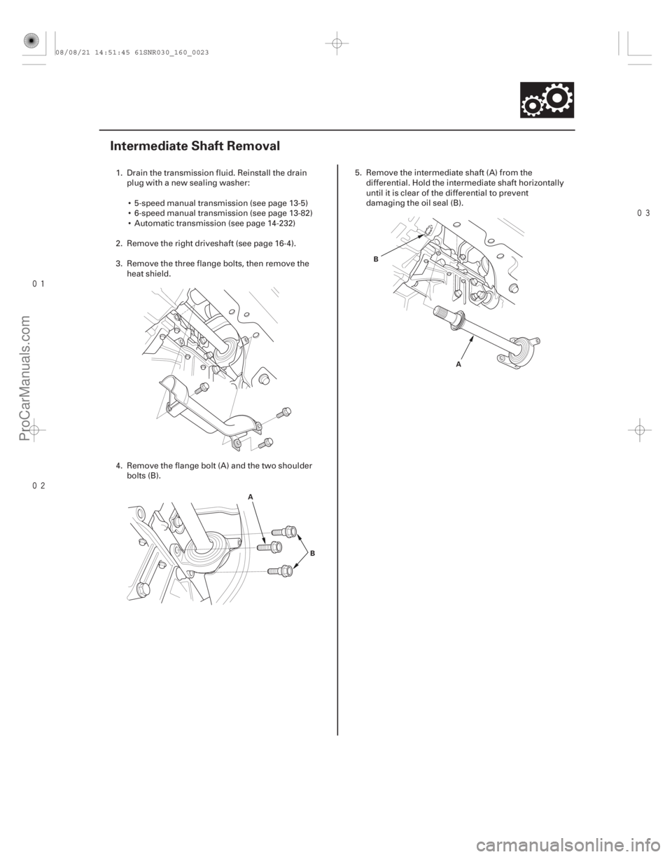
1. Drain the transmission fluid. Reinstall the drain
plug with a new sealing washer:
5-speed manual transmission (see page 13-5)
6-speed manual transmission (see page 13-82)
Automatic transmission (see page 14-232)
2. Remove the right driveshaft (see page 16-4).
3. Remove the three flange bolts, then remove the heat shield.
4. Remove the flange bolt (A) and the two shoulder bolts (B). 5. Remove the intermediate shaft (A) from the
differential. Hold the intermediate shaft horizontally
until it is clear of the differential to prevent
damaging the oil seal (B).
08/08/21 14:51:45 61SNR030_160_0023
ProCarManuals.com
DYNOMITE -2009-
Page 1317 of 2893
����
Special Tools Required
16-24
Driveline/Axle
Intermediate Shaft Disassembly
B
A
B
PRESS AB
E
C
07JAF-SH20400
D
07965-SD90100")
����
���� �����
���
�(�#�'�����������
���������������������!�����)����
Special Tools Required
16-24
Driveline/Axle
Intermediate Shaft Disassembly
B
A
B
PRESS AB
E
C
07JAF-SH20400
D
07965-SD90100 B
A
PRESSA
B
07965-SD90100 C
07947-SB00100
07JAF-SH20400
Support base attachment 07JAF-SH20400
Oil seal driver, 44.5 mm 07947-SB00100
Support base 07965-SD90100
1. Remove the outer seal (A) and the external snap ring (B).
2. Press the intermediate shaft (A) out of the intermediate shaft bearing (B) using the support
base attachment (C), the support base (D), and a
press. Be careful not to damage the bearing
support rings (E) on the intermediate shaft during
disassembly. 3. Remove the internal snap ring (A) from the bearing
support (B).
4. Press the intermediate shaft bearing (A) out of the bearing support (B) using the half shaft base, the
support base attachment, the 44.5 mm oil seal
driver (C), and a press.
08/08/21 14:51:46 61SNR030_160_0024
ProCarManuals.com
DYNOMITE -2009-
Page 1319 of 2893

PRESS
B
D
07749-0010000
C
07746-0010400
A A
B PRESS
C
07746-0030400 A
B
A
B
Support base")
����
���������
����
Special Tools Required
16-26 Driveline/Axle
Intermediate Shaft Reassembly (cont’d)
PRESS
B
D
07749-0010000
C
07746-0010400
A A
B PRESS
C
07746-0030400 A
B
A
B
Support base attachment 07JAF-SH20400
Driver handle, 15 x 135L 07749-0010000
Bearing driver attachment, 52 x 55 mm 07746-0010400
Inner bearing driver attachment, 35 mm 07746-0030400
Oil seal driver, 64 mm 07GAD-PH70201
Support base 07965-SD90100
NOTE: Refer to the Exploded View, as needed, during
this procedure. 1. Clean the disassembled parts with solvent, and dry them with compressed air.
NOTE: Do not wash the rubber parts with solvent.
2. Press a new intermediate shaft bearing (A) into the bearing support (B) using the 52 x 55 mm bearing
driver attachment (C), the 15 x 135L driver handle
(D), and a press.
3. Install the internal snap ring (A) into the groove of the bearing support (B). 4. Press the intermediate shaft (A) into the shaft
bearing (B) using the 35 mm inner bearing driver
attachment (C) and a press.
5. Install the external snap ring (A) into the groove of the intermediate shaft (B).
Replace.
08/08/21 14:51:47 61SNR030_160_0026
ProCarManuals.com
DYNOMITE -2009-
Page 1320 of 2893
���������
����
�(�#�'�����������
��������������������� �����)����
16-2716-27
Intermediate Shaft Installation
PRESS
B
C
07GAD-PH70201
A
07JAF-SH20400 07965-SD90100 A
B
A
B
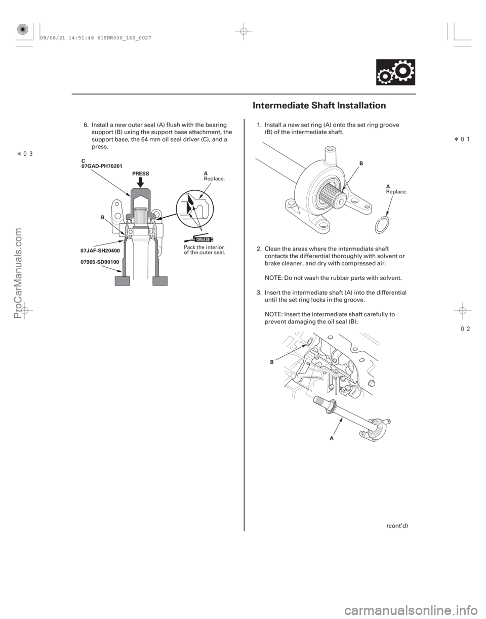
6. Install a new outer seal (A) flush with the bearing
support (B) using the support base attachment, the
support base, the 64 mm oil seal driver (C), and a
press. 1. Install a new set ring (A) onto the set ring groove
(B) of the intermediate shaft.
2. Clean the areas where the intermediate shaft contacts the differential thoroughly with solvent or
brake cleaner, and dry with compressed air.
NOTE: Do not wash the rubber parts with solvent.
3. Insert the intermediate shaft (A) into the differential until the set ring locks in the groove.
NOTE: Insert the intermediate shaft carefully to
prevent damaging the oil seal (B).
(cont’d)
Pack the interior
of the outer seal.Replace.
Replace.
08/08/21 14:51:48 61SNR030_160_0027
ProCarManuals.com
DYNOMITE -2009-
Page 1321 of 2893
���������
����
�(�#�'�����������
��������������������� �����)����
16-2716-27
Intermediate Shaft Installation
PRESS
B
C
07GAD-PH70201
A
07JAF-SH20400 07965-SD90100 A
B
A
B
6. Install a new outer seal (A) flush with the bearing
support (B) using the support base attachment, the
support base, the 64 mm oil seal driver (C), and a
press. 1. Install a new set ring (A) onto the set ring groove
(B) of the intermediate shaft.
2. Clean the areas where the intermediate shaft contacts the differential thoroughly with solvent or
brake cleaner, and dry with compressed air.
NOTE: Do not wash the rubber parts with solvent.
3. Insert the intermediate shaft (A) into the differential until the set ring locks in the groove.
NOTE: Insert the intermediate shaft carefully to
prevent damaging the oil seal (B).
(cont’d)
Pack the interior
of the outer seal.Replace.
Replace.
08/08/21 14:51:48 61SNR030_160_0027
ProCarManuals.com
DYNOMITE -2009-
Page 1352 of 2893
�����
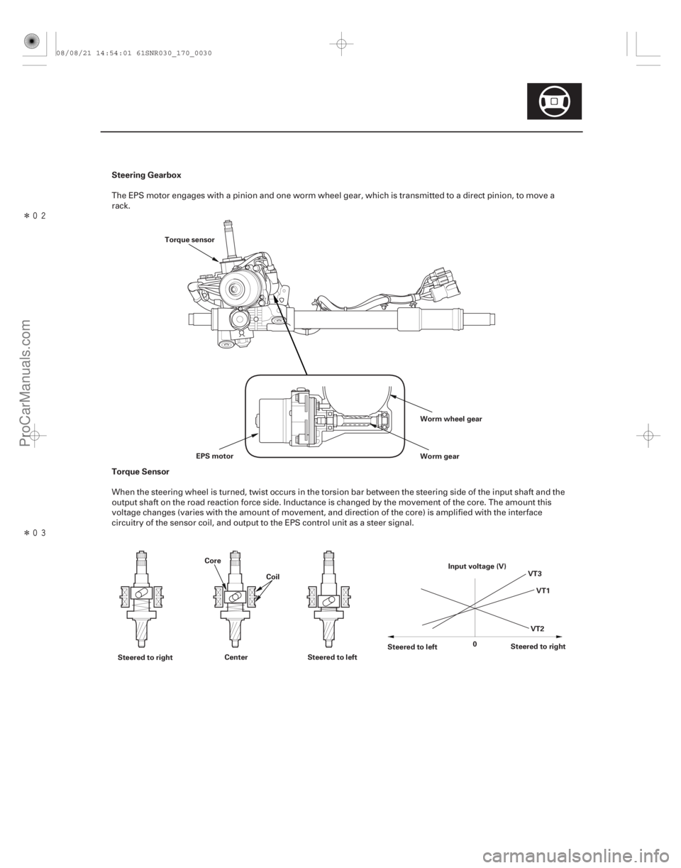
�����Steering Gearbox
Torque Sensor
17-29
Worm wheel gear
Worm gear
EPS motor
Torque sensor
Steered to right Center Steered to left Steered to left
Steered to right
0 VT1
VT3
VT2
Input voltage (V)
Core
Coil
The EPS motor engages with a pinion and one worm wheel gear, which is transmitted to a direct pinion, to move a
rack.
When the steering wheel is turned, twist occurs in the torsion bar between the steering side of the input shaft and the
output shaft on the road reaction force side. Inductance is changed by the movement of the core. The amount this
voltage changes (varies with the amount of movement, and direction of the core) is amplified with the interface
circuitry of the sensor coil, and output to the EPS control unit as a steer signal.
08/08/21 14:54:01 61SNR030_170_0030
ProCarManuals.com
DYNOMITE -2009-
Page 1388 of 2893
����
Special Tools Required
Removal
17-65
Steering Gearbox Removal and Installation
A
Ball joint remover, 28 mm 07MAC-SL0A202
Engine hang")
�Ì
�Ï ���
�(�#�'�����������
���
�����������
�
�
� �����)����
Special Tools Required
Removal
17-65
Steering Gearbox Removal and Installation
A
Ball joint remover, 28 mm 07MAC-SL0A202
Engine hanger adapter
VSB02C000015
Front subframe adaptor VSB02C000016
2006 Civic engine hanger VSB02C000025
Engine support hunger, A and Reds AAR-T1256 : These special tools are available through Honda
Canada Inc. Technical Tools Department; FAX 866-
398-8665/e-mail: ch_technicaltools ch. honda. com
Note these items during removal: Use solvent and a brush, wash any oil and dirt off the end of the steering gearbox. Avoid any electrical
parts. Blow dry with compressed air.
Be sure to remove the steering wheel before disconnecting the steering joint, or damage to the
cable reel may occur.
1. Do the battery terminal disconnection procedure (see page 22-68).
2. Raise the front of the vehicle, and support it with safety stands in the proper locations (see page
1-11).
3. Remove the front wheels.
4. Remove the driver’s airbag (see page 24-188), and the steering wheel (see page 17-6).
5. Remove the driver’s dashboard undercover (see page 20-103). 6. Remove the steering joint cover (A).
(cont’d)
08/08/21 14:55:09 61SNR030_170_0066
ProCarManuals.com
DYNOMITE -2009-
Page 1422 of 2893
����
�(�#�'�������������������������������
� �����)����
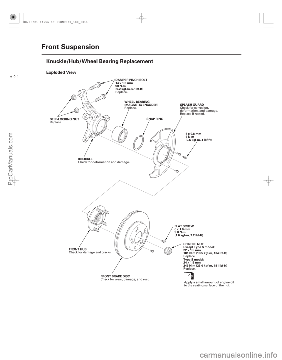
Exploded View
18-14Front Suspension
Knuckle/Hub/Wheel Bearing Replacement
SNAP RING
SELF-LOCKING NUT DAMPER PINCH BOLT
14x1.5mm
90 N·m
(9.2 kgf·m, 67 lbf·ft)
WHEEL BEARING
(MAGNETIC ENCODER) SPLASH GUARD
KNUCKLE
FLAT SCREW
6x1.0mm
9.8 N·m
(1.0 kgf·m, 7.2 lbf·ft)
FRONT HUB
FRONT BRAKE DISC SPINDLE NUT
Except Type S model:
22 x 1.5 mm
181 N·m (18.5 kgf·m, 134 lbf·ft)5x0.8mm
6N·m
(0.6 kgf·m, 4 lbf·ft)
Type S model:
24 x 1.5 mm
245 N·m (25.0 kgf·m, 181 lbf·ft)
Replace.
Replace.
Replace. Check for corrosion,
deformation, and damage.
Replace if rusted.
Check for deformation and damage.
Apply a small amount of engine oil
to the seating surface of the nut.
Check for damage and cracks.
Check for wear, damage, and rust. Replace.
Replace.
08/08/21 14:56:49 61SNR030_180_0014
ProCarManuals.com
DYNOMITE -2009-