Page 1664 of 2893

1. Install the VSA modulator-control unit onto the bracket.
2. Install the bracket with the VSA")
Installation
19-172VSA System Components
VSA Modulator-Control Unit Removal and Installation (cont’d)
1. Install the VSA modulator-control unit onto the bracket.
2. Install the bracket with the VSA modulator-control unit to the body.
3. Reconnect the six brake lines, then tighten the flare nuts to the specified torque.
4. Align the connecting surface of the VSA modulator-control unit 37P connector to the VSA modulator-control unit.
5. Pull up the lever of the VSA m
odulator-control unit 37P connector, then confirm the connector is fully seated.
6. Bleed the brake system (see page 19-9).
7. Do the VSA sensor neutral position memorization (see page 19-169).
8. Start the engine, and make sure the ABS and the VSA indicators go off.
9. Test-drive the vehicle, and make sure the ABS, and the VSA indicators do not come on. NOTE: If the brake pedal is spongy, there may be air trapped in the modulator which could then be induced into
the normal brake system during modulation. Bleed the brake system again (see page 19-9).
08/08/21 15:06:47 61SNR030_190_0172
ProCarManuals.com
DYNOMITE -2009-
Page 1667 of 2893
 and the sensor hole in the knuckle
(B).
5. Insert the guide pin to")
�����
����������
19-175
A
B
A
07AAG-SVBA100 B
07AAG-SVBA100
A
4. Apply multi-purpose grease to the wheel speedsensor O-ring (A) and the sensor hole in the knuckle
(B).
5. Insert the guide pin tool (A) into the wheel speed sensor bolt hole until the shoulder of the tool
contacts the wheel speed sensor bracket.
NOTE: To prevent O-ring damage, the wheel speed
sensor must be installed with the guide pin tool. 6. Insert the wheel speed sensor (A) and the guide pin
tool (B) into the bolt hole on the knuckle.
NOTE: To ensure proper alignment when pushing
the wheel speed sensor into the knuckle housing,
do not hold the sensor bracket during installation,
hold the sensor wire.
7. Gently push and pull the wheel speed sensor in and out to make sure the O-ring is sliding properly in its
housing. While you are doing this, make sure the
sensor doesn’t come out of the knuckle assembly. If
the sliding effort is too high, remove the wheel
speed sensor, inspect the O-ring for damage, and
start the installation process again.
8. Remove the guide pin tool, then install the bolt, and tighten it to specified torque.
9. Clean the mating surfaces between the brake disc and the inside of the wheel, then install the front
wheel.
10. Start the engine, and make sure the ABS and the VSA indicators go off.
11. Test-drive the vehicle, and make sure the ABS and the VSA indicators do not come on.
08/08/21 15:06:48 61SNR030_190_0175
ProCarManuals.com
DYNOMITE -2009-
Page 1706 of 2893
���
�(�#�'�����������
���
���������
�����
�"�����)����
20-31
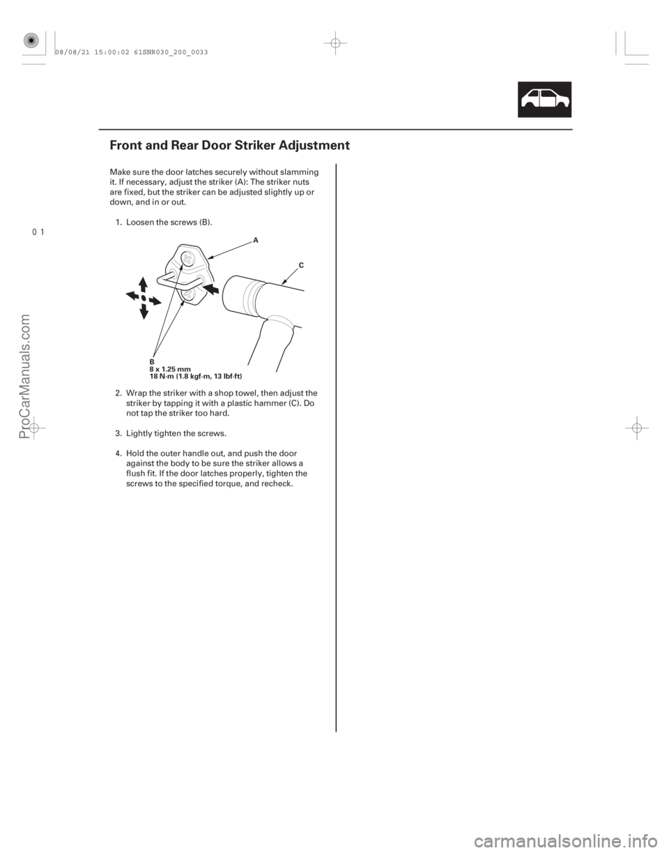
Front and Rear Door Striker Adjustment
B
8x1.25mm
18 N·m (1.8 kgf·m, 13 lbf·ft) A
C
Make sure the door latches securely without slamming
it. If necessary, adjust the striker (A): The striker nuts
are fixed, but the striker can be adjusted slightly up or
down, and in or out.1. Loosen the screws (B).
2. Wrap the striker with a shop towel, then adjust the striker by tapping it with a plastic hammer (C). Do
not tap the striker too hard.
3. Lightly tighten the screws.
4. Hold the outer handle out, and push the door against the body to be sure the striker allows a
flush fit. If the door latches properly, tighten the
screws to the specified torque, and recheck.
08/08/21 15:00:02 61SNR030_200_0033
ProCarManuals.com
DYNOMITE -2009-
Page 1790 of 2893
 A
B
C
A
B
C
B C
14. Install the dashboard in the r
everse order of
removal, and note these items:")
�
�
Special bolt tightening on passenger’s side
20-113
A
8x1.25mm
22 N·m (2.2 kgf·m, 16 lbf·ft) A
B
C
A
B
C
B C
14. Install the dashboard in the r
everse order of
removal, and note these items:
Before tightening the bolts, make sure the wire harnesses are not pinched.
Make sure the connectors are plugged in properly, and the antenna lead and each cable
are connected properly.
Before reinstalling the dashboard, screw the special bolts (A) into the adjusting nuts (B), and
check that they turn together. If they do not turn
together, replace the special bolts.
After setting the dashboard in the body, reinstall all of the mounting bolts but do not tighten them.
First tighten the driver’s side bracket bolts to the
specified torque. Next, loosen the special bolts to
turn the adjusting nuts out of the sleeves (C) until
the nuts contact the body. Then tighten the
special bolts to the specified torque.
Tighten all remaining mounting bolts to the specified torque.
Apply medium strength liquid thread lock to the bolts securing the center bracket and the
dashboard before reinstallation.
Check for any DTCs that may have been set during repairs, and clear them.
Do the battery terminal reconnection procedure (see page 22-68).
08/08/21 15:02:59 61SNR030_200_0115
ProCarManuals.com
DYNOMITE -2009-
Page 1797 of 2893
�
��
Passenger’s Seat
20-12020-120 Seats
Front Seat Removal/Installation
(cont’d)
Front Seat Frame Replacement
Fastener Locations
:Bolt,4
10x")
���
���
�(�#�'���������������
����������������� �����)�
��
Passenger’s Seat
20-12020-120 Seats
Front Seat Removal/Installation
(cont’d)
Front Seat Frame Replacement
Fastener Locations
:Bolt,4
10x1.25mm
34 N·m
(3.5 kgf·m, 25 lbf·ft) A
A
B
C
Fastener Locations
:Clip,4
A
9. With the help of an assistant, carefully remove thefront seat through the front door opening.
10. Install the seat in the reverse order of removal, and note these items:
Apply medium strength liquid thread lock to the seat mounting bolts before reinstallation.
Tighten the seat mounting bolts to the specified torque in the sequence shown. Slide the seat (A)
all the way back and tighten and , then slide
it forward and tighten and . The driver’s seat
is shown; the passenger’s seat is similar.
Tighten the bolts by hand first, then tighten them to specification with a torque wrench.
Make sure each connector is plugged in properly.
Check for any DTCs that may have been set during repairs, and clear them.
Do the battery terminal reconnection procedure (see page 22-68). Calibrate the ODS unit after any of these actions
(see page 24-27):
Front passenger’s seat replacement (including any seat components)
Replacement of the front seat weight sensors
After a vehicle collision
NOTE: Put on gloves to protect your hands.
Apply oil to the pivot portions of the slide locks.
Apply multipurpose grease to the sliding portions of the seat tracks.
If the side airbag has deployed, replace the seat frame and related pieces with new ones (see page
24-185).
1. Remove the front seat (see page 20-118).
2. Remove these items: Front seat-back cover (see page 20-123)
Front seat cushion cover (see page 20-127)
ODS unit (see page 24-209)
Front seat belt buckle (see page 24-6)
3. Remove the clips, then remove the recline inner covers (A) and module holder (B) from the seat
frame (C).
08/08/21 15:03:55 61SNR030_200_0122
ProCarManuals.com
DYNOMITE -2009-
Page 1798 of 2893
�
��
Passenger’s Seat
20-12020-120 Seats
Front Seat Removal/Installation
(cont’d)
Front Seat Frame Replacement
Fastener Locations
:Bolt,4
10x")
���
���
�(�#�'���������������
����������������� �����)�
��
Passenger’s Seat
20-12020-120 Seats
Front Seat Removal/Installation
(cont’d)
Front Seat Frame Replacement
Fastener Locations
:Bolt,4
10x1.25mm
34 N·m
(3.5 kgf·m, 25 lbf·ft) A
A
B
C
Fastener Locations
:Clip,4
A
9. With the help of an assistant, carefully remove thefront seat through the front door opening.
10. Install the seat in the reverse order of removal, and note these items:
Apply medium strength liquid thread lock to the seat mounting bolts before reinstallation.
Tighten the seat mounting bolts to the specified torque in the sequence shown. Slide the seat (A)
all the way back and tighten and , then slide
it forward and tighten and . The driver’s seat
is shown; the passenger’s seat is similar.
Tighten the bolts by hand first, then tighten them to specification with a torque wrench.
Make sure each connector is plugged in properly.
Check for any DTCs that may have been set during repairs, and clear them.
Do the battery terminal reconnection procedure (see page 22-68). Calibrate the ODS unit after any of these actions
(see page 24-27):
Front passenger’s seat replacement (including any seat components)
Replacement of the front seat weight sensors
After a vehicle collision
NOTE: Put on gloves to protect your hands.
Apply oil to the pivot portions of the slide locks.
Apply multipurpose grease to the sliding portions of the seat tracks.
If the side airbag has deployed, replace the seat frame and related pieces with new ones (see page
24-185).
1. Remove the front seat (see page 20-118).
2. Remove these items: Front seat-back cover (see page 20-123)
Front seat cushion cover (see page 20-127)
ODS unit (see page 24-209)
Front seat belt buckle (see page 24-6)
3. Remove the clips, then remove the recline inner covers (A) and module holder (B) from the seat
frame (C).
08/08/21 15:03:55 61SNR030_200_0122
ProCarManuals.com
DYNOMITE -2009-
Page 1836 of 2893
���
�(�#�'�����������
���������������������"�����)����
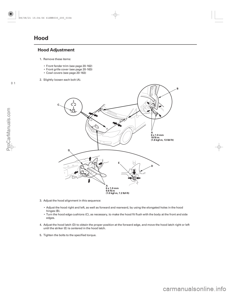
20-152Hood
Hood Adjustment
B
C
D
E A
6x1.0mm
18 N·m
(1.8 kgf·m, 13 lbf·ft)
A
6x1.0mm
9.8 N·m
(1.0 kgf·m, 7.2 lbf·ft)
D
1. Remove these items:
Front fender trim (see page 20-162)
Front grille cover (see page 20-163)
Cowl covers (see page 20-163)
2. Slightly loosen each bolt (A).
3. Adjust the hood alignment in this sequence: Adjust the hood right and left, as well as forward and rearward, by using the elongated holes in the hoodhinges (B).
Turn the hood edge cushions (C), as necessary, to make the hood fit flush with the body at the front and side edges.
4. Adjust the hood latch (D) to obtain the proper position at the forward edge, and move the hood latch right or left until the striker (E) is centered in the hood latch.
5. Tighten the bolts to the specified torque.
08/08/21 15:04:56 61SNR030_200_0154
ProCarManuals.com
DYNOMITE -2009-
Page 1840 of 2893
����
20-155
Trunk Lid
Trunk Lid Adjustment
A
B
C D G
H
E
6x1.0mm
18 N·m
(1.8 kgf·m, 13 lbf·ft)
E
6x1.0mm
9.8 N·m (1.0 kgf·m, 7.2 lbf·ft)
H F
F
1")
���
�(�#�'�����������
���������������������"�����)����
20-155
Trunk Lid
Trunk Lid Adjustment
A
B
C D G
H
E
6x1.0mm
18 N·m
(1.8 kgf·m, 13 lbf·ft)
E
6x1.0mm
9.8 N·m (1.0 kgf·m, 7.2 lbf·ft)
H F
F
1. Remove the rear shelf (see page 20-78).
2. Pry up on the notch (A) to release the rear hooks (B) and pivot the striker trim cap (C) on the front hooks (D), thenremove the cap. Slightly loosen each bolt (E).
3. Adjust the trunk lid alignment in the following sequence: Adjust the trunk lid hinges (F) right and left, as well as forward and rearward, by using the elongated holes. Takecare not to hit the rear window when loosening the bolts.
Turn the trunk lid edge cushions (G), in or out as necessary, to make the trunk lid fit flush with the body at the rear and side edges.
Adjust the fit between the trunk lid and the trunk lid opening by moving the striker (H).
4. Tighten the bolts to the specified torque.
5. Make sure the trunk lid opens properly and locks securely.
6. Reinstall all removed parts.
08/08/21 15:04:57 61SNR030_200_0157
ProCarManuals.com
DYNOMITE -2009-