Page 2688 of 2893
����
����
���
����
�(�#�'�������������������������������
�"�����)����
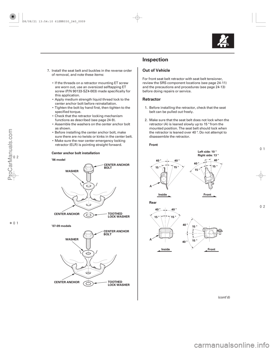
Center anchor bolt installation
Front
Rear
Out of Vehicle
Retractor
24-924-9
Inspection
CENTER ANCHOR
BOLT
WASHER
TOOTHED
LOCK WASHER
CENTER ANCHOR
’06 model
CENTER ANCHOR
BOLT
WASHER
TOOTHED
LOCK WASHER
CENTER ANCHOR
’07-09 models Left side: 10 °
Right side: 13 °
40 ° 40 °
40 °
40 °
15 °
15 °
15 °
15 °
A Inside Front
40 °
40 °40 °
40 °
15 ° 15 °
15 °
15 °
A Inside Front
7. Install the seat belt and buckles in the reverse order
of removal, and note these items:
If the threads on a retractor mounting ET screw are worn out, use an oversized selftapping ET
screw (P/N 90133-SZ4-003) made specifically for
this application.
Apply medium strength liquid thread lock to the center anchor bolt before reinstallation.
Tighten the bolt by hand first, then tighten to the specified torque.
Check that the retractor locking mechanism functions as described (see page 24-9).
Assemble the washers on the center anchor bolt as shown.
Before installing the center anchor bolt, make sure there are no twists or kinks in the center belt.
Make sure the rear center emergency locking retractor (ELR) is pointing straight forward. For front seat belt retractor with seat belt tensioner,
review the SRS component locations (see page 24-11)
and the precautions and procedures (see page 24-13)
before doing repairs or service.
1. Before installing the retractor, check that the seat belt can be pulled out freely.
2. Make sure that the seat belt does not lock when the retractor (A) is leaned slowly up to 15 ° from the
mounted position. The seat belt should lock when
the retractor is leaned over 40 °. Do not attempt to
disassemble the retractor.
(cont’d)
08/08/21 13:54:10 61SNR030_240_0009
ProCarManuals.com
DYNOMITE -2009-
Page 2689 of 2893
����
����
���
����
�(�#�'�������������������������������
�"�����)����
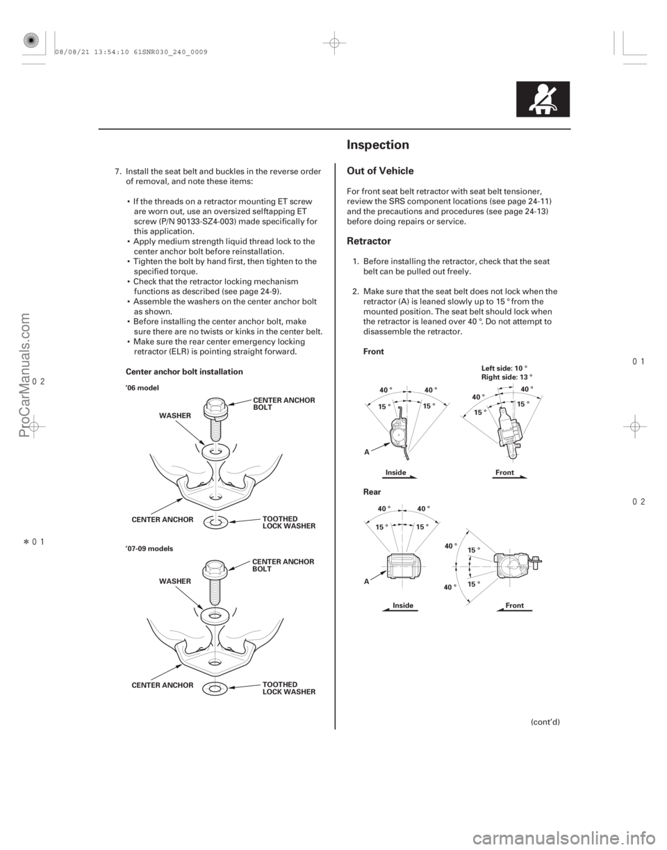
Center anchor bolt installation
Front
Rear
Out of Vehicle
Retractor
24-924-9
Inspection
CENTER ANCHOR
BOLT
WASHER
TOOTHED
LOCK WASHER
CENTER ANCHOR
’06 model
CENTER ANCHOR
BOLT
WASHER
TOOTHED
LOCK WASHER
CENTER ANCHOR
’07-09 models Left side: 10 °
Right side: 13 °
40 ° 40 °
40 °
40 °
15 °
15 °
15 °
15 °
A Inside Front
40 °
40 °40 °
40 °
15 ° 15 °
15 °
15 °
A Inside Front
7. Install the seat belt and buckles in the reverse order
of removal, and note these items:
If the threads on a retractor mounting ET screw are worn out, use an oversized selftapping ET
screw (P/N 90133-SZ4-003) made specifically for
this application.
Apply medium strength liquid thread lock to the center anchor bolt before reinstallation.
Tighten the bolt by hand first, then tighten to the specified torque.
Check that the retractor locking mechanism functions as described (see page 24-9).
Assemble the washers on the center anchor bolt as shown.
Before installing the center anchor bolt, make sure there are no twists or kinks in the center belt.
Make sure the rear center emergency locking retractor (ELR) is pointing straight forward. For front seat belt retractor with seat belt tensioner,
review the SRS component locations (see page 24-11)
and the precautions and procedures (see page 24-13)
before doing repairs or service.
1. Before installing the retractor, check that the seat belt can be pulled out freely.
2. Make sure that the seat belt does not lock when the retractor (A) is leaned slowly up to 15 ° from the
mounted position. The seat belt should lock when
the retractor is leaned over 40 °. Do not attempt to
disassemble the retractor.
(cont’d)
08/08/21 13:54:10 61SNR030_240_0009
ProCarManuals.com
DYNOMITE -2009-
Page 2695 of 2893
��������
SRS Unit, Front and Side Impact Sensors,
Driver’s Seat Position Sensor, Front
Passenger’s Weight Sensors and, Rear
Safing Sensor
24-15
NOTE: Some systems store data in memory that is lost
when the battery is disconnected. Before disconnecting
the battery, refer to Battery Terminal Disconnection and
Reconnection (see page 22-68).
Turn the ignition switch to LOCK (0), disconnect the negative cable from the battery, then wait at least 3
minutes before starting installation or replacement of
the SRS unit, or disconnecting the connectors from
the SRS unit.
Be careful not to bump or impact the SRS unit, the front impact sensors, the side impact sensors, or the
rear safing sensor whenever the ignition switch is in
ON (II), or for at least 3 minutes after the ignition
switch is turned to LOCK (0).
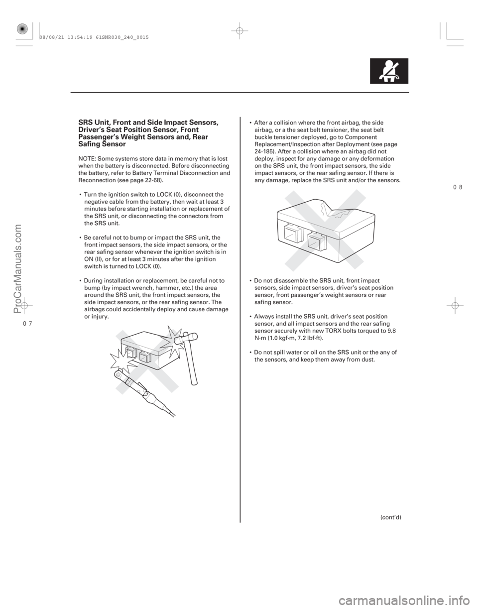
During installation or replacement, be careful not to bump (by impact wrench, hammer, etc.) the area
around the SRS unit, the front impact sensors, the
side impact sensors, or the rear safing sensor. The
airbags could accidentally deploy and cause damage
or injury. After a collision where the front airbag, the side
airbag, or a the seat belt tensioner, the seat belt
buckle tensioner deployed, go to Component
Replacement/Inspection after Deployment (see page
24-185). After a collision where an airbag did not
deploy, inspect for any damage or any deformation
on the SRS unit, the front impact sensors, the side
impact sensors, or the rear safing sensor. If there is
any damage, replace the SRS unit and/or the sensors.
Do not disassemble the SRS unit, front impact sensors, side impact sensors, driver’s seat position
sensor, front passenger’s weight sensors or rear
safing sensor.
Always install the SRS unit, driver’s seat position sensor, and all impact sensors and the rear safing
sensor securely with new TORX bolts torqued to 9.8
N·m (1.0 kgf·m, 7.2 lbf·ft).
Do not spill water or oil on the SRS unit or the any of the sensors, and keep them away from dust.
(cont’d)
08/08/21 13:54:19 61SNR030_240_0015
ProCarManuals.com
DYNOMITE -2009-
Page 2872 of 2893
���
����
�(�#�'�������������������������������
� �����)����
Removal Installation
24-191
Side Airbag Replacement
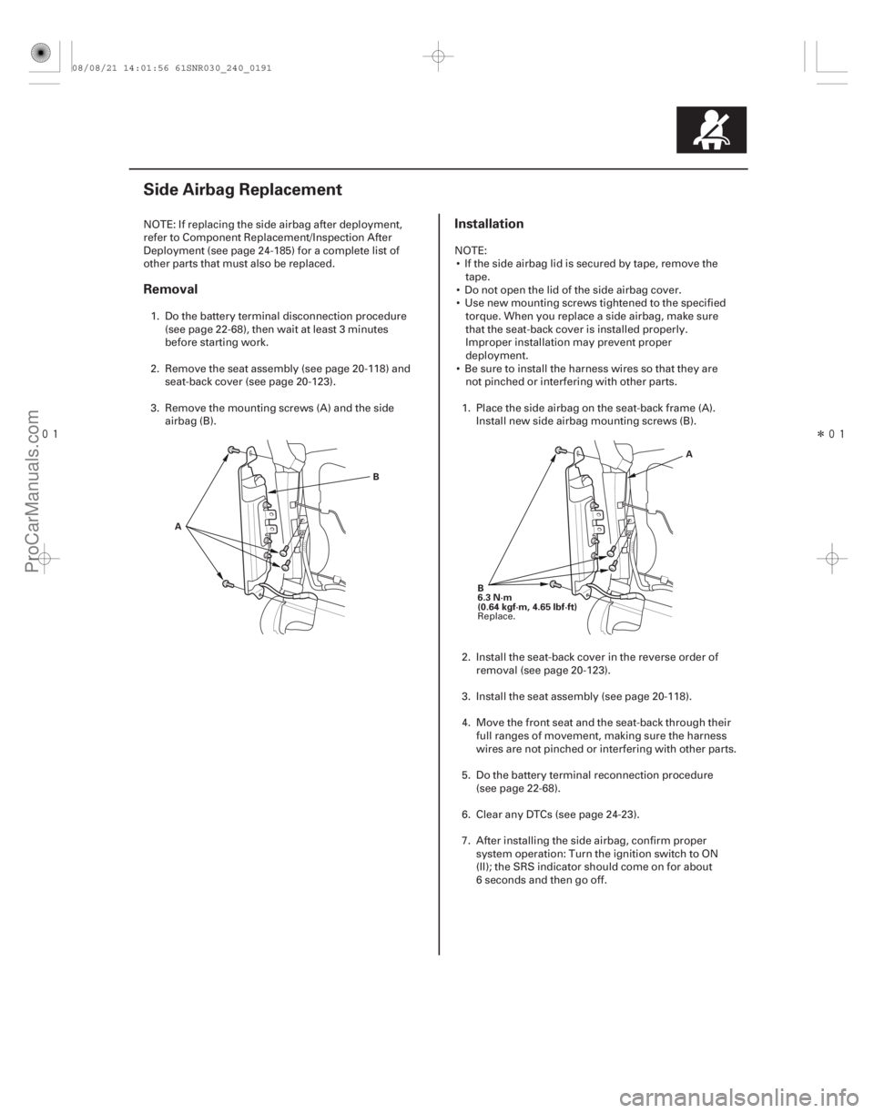
AB
A
B
6.3 N·m
(0.64 kgf·m, 4.65 lbf·ft)
NOTE: If replacing the side airbag after deployment,
refer to Component Replacement/Inspection After
Deployment (see page 24-185) for a complete list of
other parts that must also be replaced. 1. Do the battery terminal disconnection procedure (see page 22-68), then wait at least 3 minutes
before starting work.
2. Remove the seat assembly (see page 20-118) and seat-back cover (see page 20-123).
3. Remove the mounting screws (A) and the side airbag (B). NOTE:
If the side airbag lid is secured by tape, remove the tape.
Do not open the lid of the side airbag cover.
Use new mounting screws tightened to the specified torque. When you replace a side airbag, make sure
that the seat-back cover is installed properly.
Improper installation may prevent proper
deployment.
Be sure to install the harness wires so that they are not pinched or interfering with other parts.
1. Place the side airbag on the seat-back frame (A). Install new side airbag mounting screws (B).
2. Install the seat-back cover in the reverse order of removal (see page 20-123).
3. Install the seat assembly (see page 20-118).
4. Move the front seat and the seat-back through their full ranges of movement, making sure the harness
wires are not pinched or interfering with other parts.
5. Do the battery terminal reconnection procedure (see page 22-68).
6. Clear any DTCs (see page 24-23).
7. After installing the side airbag, confirm proper system operation: Turn the ignition switch to ON
(II); the SRS indicator should come on for about
6 seconds and then go off.
Replace.
08/08/21 14:01:56 61SNR030_240_0191
ProCarManuals.com
DYNOMITE -2009-
Page 2889 of 2893
����
��������
24-208SRS
Front Passenger’s Weight Sensor Replacement (cont’d)
A
42 N·m
(4.2 kgf·m, 30 lbf·ft)
07744-0010300
MORE THAN
4mm(0.2in.)
A
B B B
B
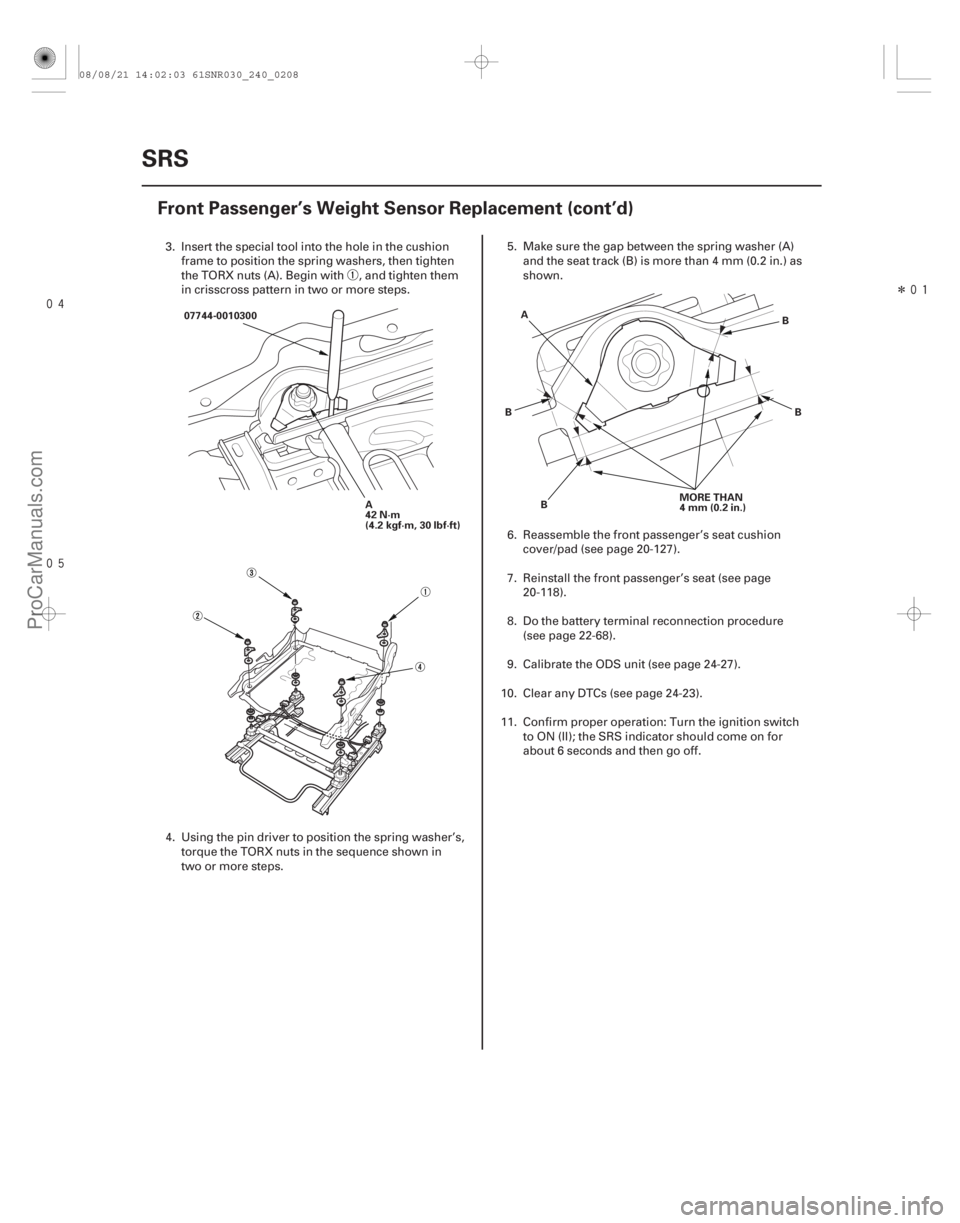
3. Insert the special tool into the hole in the cushion frame to position the spring washers, then tighten
the TORX nuts (A). Begin with , and tighten them
in crisscross pattern in two or more steps.
4. Using the pin driver to position the spring washer’s, torque the TORX nuts in the sequence shown in
two or more steps. 5. Make sure the gap between the spring washer (A)
and the seat track (B) is more than 4 mm (0.2 in.) as
shown.
6. Reassemble the front passenger’s seat cushion cover/pad (see page 20-127).
7. Reinstall the front passenger’s seat (see page 20-118).
8. Do the battery terminal reconnection procedure (see page 22-68).
9. Calibrate the ODS unit (see page 24-27).
10. Clear any DTCs (see page 24-23).
11. Confirm proper operation: Turn the ignition switch to ON (II); the SRS indicator should come on for
about 6 seconds and then go off.
08/08/21 14:02:03 61SNR030_240_0208
ProCarManuals.com
DYNOMITE -2009-