Page 1453 of 2893
����
�������
�(�#�'���������������
���������������
� �����)����
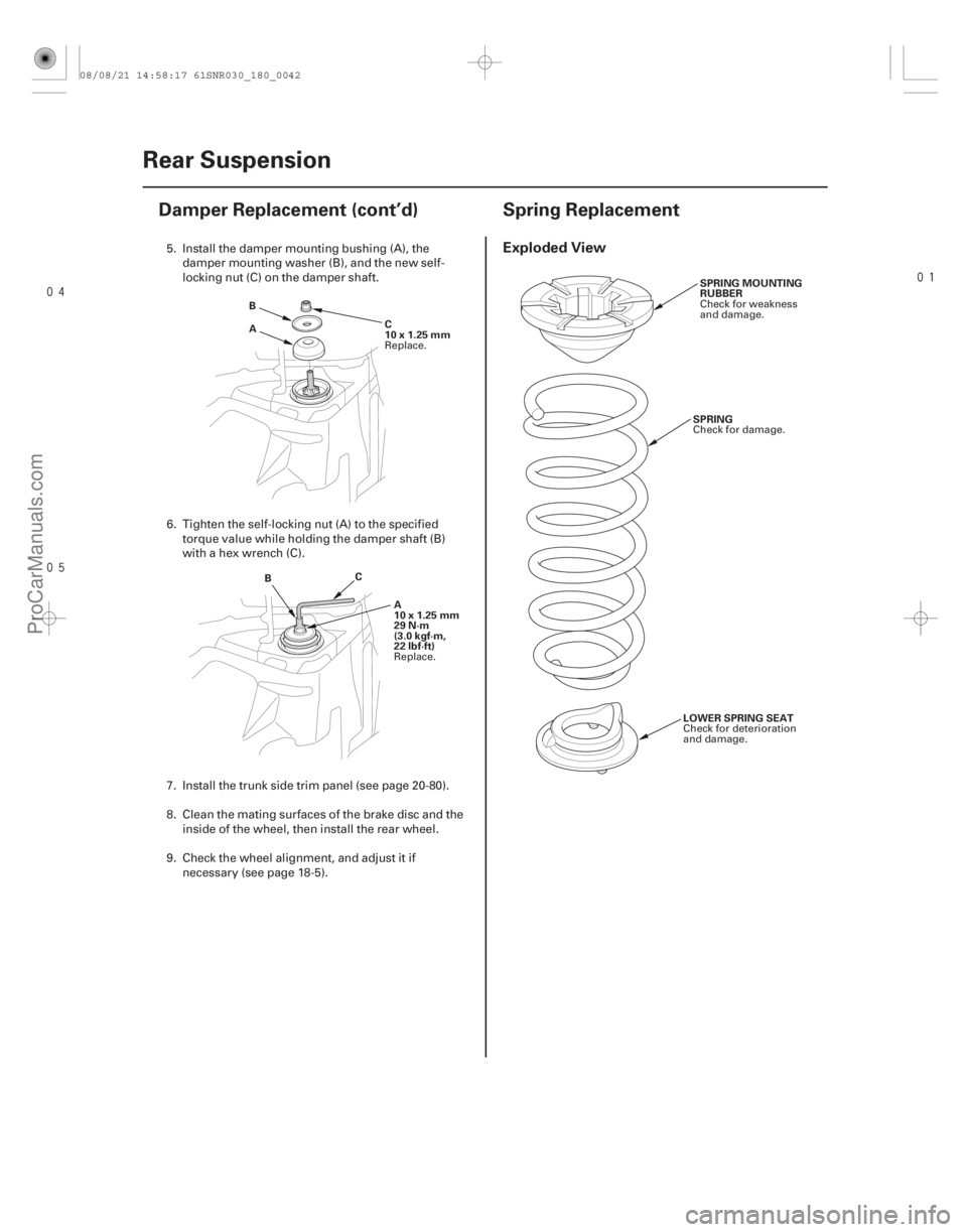
Exploded View
18-4218-42 Rear Suspension
Damper Replacement (cont’d) Spring Replacement
A
B
C
10x1.25mm
B C
A
10x1.25mm
29 N·m
(3.0 kgf·m,
22 lbf·ft) SPRING MOUNTING
RUBBER
SPRING
LOWER SPRING SEAT
5. Install the damper mounting bushing (A), the damper mounting washer (B), and the new self-
locking nut (C) on the damper shaft.
6. Tighten the self-locking nut (A) to the specified torque value while holding the damper shaft (B)
with a hex wrench (C).
7. Install the trunk side trim panel (see page 20-80).
8. Clean the mating surfaces of the brake disc and the inside of the wheel, then install the rear wheel.
9. Check the wheel alignment, and adjust it if necessary (see page 18-5).
Replace.
Replace. Check for weakness
and damage.
Check for damage.
Check for deterioration
and damage.
08/08/21 14:58:17 61SNR030_180_0042
ProCarManuals.com
DYNOMITE -2009-
Page 1454 of 2893
����
�������
�(�#�'���������������
���������������
� �����)����
Exploded View
18-4218-42 Rear Suspension
Damper Replacement (cont’d) Spring Replacement
A
B
C
10x1.25mm
B C
A
10x1.25mm
29 N·m
(3.0 kgf·m,
22 lbf·ft) SPRING MOUNTING
RUBBER
SPRING
LOWER SPRING SEAT
5. Install the damper mounting bushing (A), the damper mounting washer (B), and the new self-
locking nut (C) on the damper shaft.
6. Tighten the self-locking nut (A) to the specified torque value while holding the damper shaft (B)
with a hex wrench (C).
7. Install the trunk side trim panel (see page 20-80).
8. Clean the mating surfaces of the brake disc and the inside of the wheel, then install the rear wheel.
9. Check the wheel alignment, and adjust it if necessary (see page 18-5).
Replace.
Replace. Check for weakness
and damage.
Check for damage.
Check for deterioration
and damage.
08/08/21 14:58:17 61SNR030_180_0042
ProCarManuals.com
DYNOMITE -2009-
Page 1457 of 2893

’07-08 except Type S models:
12x1.25mm
110N·m(11.2kgf·m,81.0lbf·ft)
’07-08 Type S models:
12x1.25mm
115N·m(11.7k")
����
���� ����
18-45
A
’06 model:
12x1.25mm
108N·m(11.0kgf·m,79.6lbf·ft)
’07-08 except Type S models:
12x1.25mm
110N·m(11.2kgf·m,81.0lbf·ft)
’07-08 Type S models:
12x1.25mm
115N·m(11.7kgf·m,84.6lbf·ft)
’09 model:
12x1.25mm
115N·m(11.7kgf·m,84.6lbf·ft)
A
12x1.25mm
108 N·m
(11.0 kgf·m,
79.6 lbf·ft)
B
C A
B
C
Except Type S model:
12x1.25mm
59 N·m
(6.0 kgf·m, 43 lbf·ft)
Type S model:
12x1.25mm
69 N·m
(7.0 kgf·m, 51 lbf·ft)
3. Loosely install new trailing arm front m ounting
bolts (A).
4. Loosely install the new flange bolt (A) that connects the knuckle (B) and the upper arm (C). 5. Slowly raise the jack until you can align the bolt
hole with the holes in the trailing arm (A) and the
damper (B), and install the new flange bolt (C).
6. Install the stabilizer link on the trailing arm (see page 18-37).
7. Raise the rear suspension with a floor jack to load the vehicle weight.
8. Tighten all mounting hardware to the specified torque values.
(cont’d)
Replace.
Replace.
Replace.
Replace.Replace. Replace.
Replace.
08/08/21 14:58:19 61SNR030_180_0045
ProCarManuals.com
DYNOMITE -2009-
Page 1491 of 2893

A
BC
D
4N·m
(0.4 kgf·m, 3 lbf·ft)
F
E
OUT SIDE
WHEEL CENTER F
E EA
B
C
1. Before installing the tire pressure sensor, clean the
mating")
��������
18-78TPMS
Tire Pressure Sensor Replacement (cont’d)
A
BC
D
4N·m
(0.4 kgf·m, 3 lbf·ft)
F
E
OUT SIDE
WHEEL CENTER F
E EA
B
C
1. Before installing the tire pressure sensor, clean the
mating surfaces on the sensor and the wheel.
2. Install the tire pressure sensor (A) and the washer (B) to the wheel (C), and tighten the valve stem nut
(D) finger tight. Make sure the pressure sensor is
restingonthewheel.
NOTE: Install the tire pressure sensor so that
sensor housing surface (E) should not exceed
protrusion (F) of wheel to prevent the sensor
housing from being caught on the bead of the tire
when assembling the tire.
3. Tighten the valve stem nut to the specified torque while holding the tire pressure sensor.
NOTE: Do not use air or electric impact tools to tighten a valve stem nut.
Do not twist the tire pressure sensor to adjust its position with the wheel, as this will damage or
deform the valve stem grommet. 4. Lube the tire bead sparingly with a paste-type tire
mounting lubricant, and position the wheel so the
tire machine (A) and tire iron (B) are next to the
valve stem (C) and will move away from it when
the machine starts. Then install the tire onto the
wheel.
5. With a dry air source, inflate the tire to 300 kPa (3.1 kgf/cm , 44 psi) to seat the tire bead to the rim,
then adjust the tire pressure (see page 18-5), then
install the valve stem cap.
NOTE: Make sure the tire bead is seated on both
sides of the rim uniformly.
6. Check and adjust the wheel balance, then install the wheels on the vehicle.
7. Remove the jack stands, and lower the vehicle. Torque the wheel nuts to specification.
8. Connect the HDS, and memorize the tire pressure sensor IDs using the TPMS sensor initializer tool
(see page 18-52).
2
08/08/21 14:59:02 61SNR030_180_0078
ProCarManuals.com
DYNOMITE -2009-
Page 1507 of 2893

Service limit: 1.6 mm (0.06 in.)
Inner pad
Outer pad
19-15
A
10x1.0mm
50 N·m
(5.1 kgf·m,
37 l")
�������
����
�µ�µ
Inspection - Type S Model
Brake pad thickness:
Standard: 9.0 9.7 mm (0.35 0.38 in.)
Service limit: 1.6 mm (0.06 in.)
Inner pad
Outer pad
19-15
A
10x1.0mm
50 N·m
(5.1 kgf·m,
37 lbf·ft)
B
A B
A
C
16. Pivot the caliper down into position. Install the flange bolt (A), and tighten it to the specified torque
while holding the caliper pin (B) with a wrench
being careful not to damage the pin boot.
17. Clean the mating surfaces between the brake disc and the inside of the wheel, then install the front
wheels.
18. Press the brake pedal several times to make sure the brakes work.
NOTE: Engagement may require a greater pedal
stroke immediately after the brake pads have been
replaced as a set. Several applications of the brake
pedal will restore the normal pedal stroke.
19. Add brake fluid as needed.
20. After installation, check for leaks at hose and line joints or connections, and retighten if necessary.
Test-drive the vehicle, then recheck for leaks
(see page 19-37). 1. Raise the front of the vehicle, and support it with
safety stands in the proper locations (see page
1-11).
2. Remove the front wheels.
3. Check the thickness (A) of the inner pad (B) and the outer pad (C). Do not include the thickness of the
backing plate.
4. If any part of the brake pad thickness is less than the service limit, replace the front brake pads as a
set.
5. Clean the mating surfaces between the brake disc and the inside of the wheel, then install the front
wheels.
(cont’d)
08/08/21 15:00:55 61SNR030_190_0015
ProCarManuals.com
DYNOMITE -2009-
Page 1510 of 2893
����
19-18Conventional Brake Components
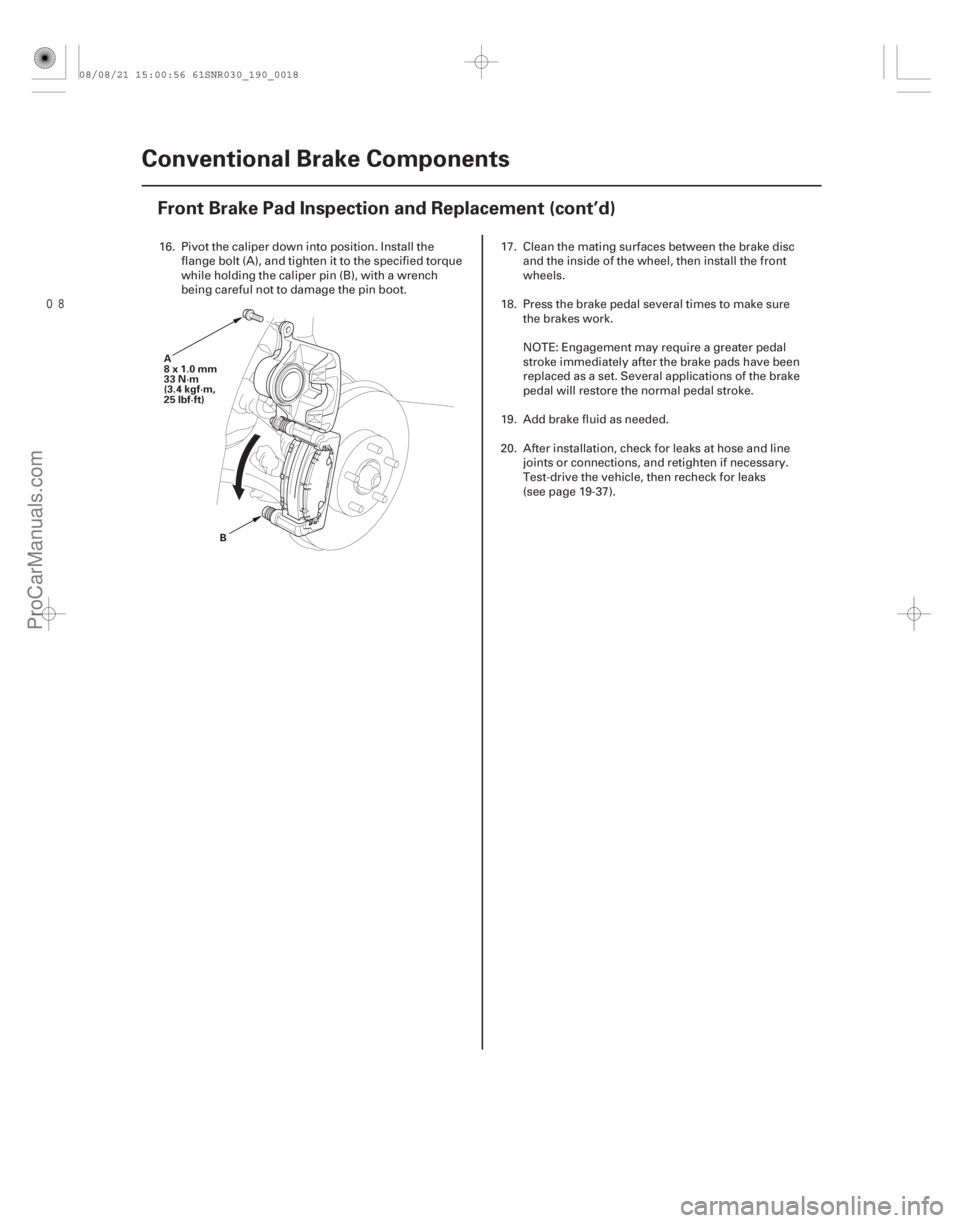
Front Brake Pad Inspection and Replacement (cont’d)
A
8x1.0mm
33 N·m
(3.4 kgf·m,
25 lbf·ft)
B
16. Pivot the caliper down into position. Install theflange bolt (A), and tighten it to the specified torque
while holding the caliper pin (B), with a wrench
being careful not to damage the pin boot. 17. Clean the mating surfaces between the brake disc
and the inside of the wheel, then install the front
wheels.
18. Press the brake pedal several times to make sure the brakes work.
NOTE: Engagement may require a greater pedal
stroke immediately after the brake pads have been
replaced as a set. Several applications of the brake
pedal will restore the normal pedal stroke.
19. Add brake fluid as needed.
20. After installation, check for leaks at hose and line joints or connections, and retighten if necessary.
Test-drive the vehicle, then recheck for leaks
(see page 19-37).
08/08/21 15:00:56 61SNR030_190_0018
ProCarManuals.com
DYNOMITE -2009-
Page 1511 of 2893
�
��
Runout
Brake disc runout:Service limit: 0.04 mm (0.0016 in.) Max. refinishing limit:
Except Type S model: 21.0 mm (0.83 in.)
Type S model: 23.0 m")
���
�(�#�'�����������
�����������
�������
�"�����)�
��
Runout
Brake disc runout:Service limit: 0.04 mm (0.0016 in.) Max. refinishing limit:
Except Type S model: 21.0 mm (0.83 in.)
Type S model: 23.0 mm (0.91 in.)
19-19
Front Brake Disc Inspection
B
108 N·m
(11.0 kgf·m, 79.6 lbf·ft) A
10 mm
(0.39 in.)
1. Raise the front of the vehicle, and support it with
safety stands in the proper locations (see page
1-11).
2. Remove the front wheels.
3. Remove the brake pads: Except Type S model (see page 19-13), Type S model (see page 19-16).
4. Inspect the brake disc to wheel surface for damage and cracks. Clean the brake disc thoroughly, and
remove all rust.
5. Install suitable flat washers (A) and wheel nuts (B), and tighten the wheel nuts to the specified torque
to hold the brake disc securely against the hub.
6. Set up the dial gauge against the brake disc as shown, and measure the runout at 10 mm (0.39 in.)
from the outer edge of the brake disc. 7. If the brake disc is beyond the service limit, refinish
the brake disc with a Honda-approved
commercially available on-car brake lathe.
NOTE: If the brake disc is beyond the service limit for refinishing, replace it (see page 19-21).
If the brake disc is replaced with a new one, check the new disc for runout. If the new disc is
out of specification, refinish the disc.
8. Install the brake pads: Except Type S model (see page 19-13), Type S model (see page 19-16).
9. Clean the mating surfaces between the brake disc and the inside of the wheel, then install the front
wheels.
(cont’d)
08/08/21 15:00:57 61SNR030_190_0019
ProCarManuals.com
DYNOMITE -2009-
Page 1523 of 2893
D
8x1.0mm
23 N·m
(2.3 kgf·m,
17 lbf·ft)
A B
C
14. Rotate the caliper piston (A) clockwise into the
cylinder, then align the cutout (B) in the p")
����
19-31
E
8x1.25mm
22 N·m
(2.2 kgf·m, 16 lbf·ft)D
8x1.0mm
23 N·m
(2.3 kgf·m,
17 lbf·ft)
A B
C
14. Rotate the caliper piston (A) clockwise into the
cylinder, then align the cutout (B) in the piston with
the tab (C) on the inner pad by turning the piston
back. Lubricate the boot with rubber grease to
avoid twisting the piston boot. If the piston boot is
twisted, back it out so it is positioned properly.
NOTE: Be careful when moving the piston back in
the caliper; brake fluid might overflow from the
master cylinder’s reservoir. If brake fluid gets on
any painted surface, wash it off immediately with
water.
15. Install the caliper. Install the flange bolts (D), and tighten it to the specified torque while holding the
respective caliper pin with a wrench being careful
not to damage the pin boots.
16. Install the brake hose mounting bolt (E).
17. Clean the mating surfaces between the brake disc and the inside of the wheel, then install the rear
wheels. 18. Press the brake pedal several times to make sure
the brakes work.
NOTE: Engagement may require a greater pedal
stroke immediately after the brake pads have been
replaced as a set. Several applications of the brake
pedal will restore the normal pedal stroke.
19. Add brake fluid as needed.
20. After installation, check for leaks at hose and line joints or connections, and retighten if necessary.
Test-drive the vehicle, then recheck for leaks
(see page 19-37).
08/08/21 15:02:05 61SNR030_190_0031
ProCarManuals.com
DYNOMITE -2009-