Page 1524 of 2893
����
Runout
Brake disc runout:Service limit: 0.04 mm (0.0016 in.) Max. refinishing limit: 8.0 mm (0.31 in.)
19-32
Conventional Brake Components
Rear B")
���
�(�#�'�����������
�����������
�������
�"�����)����
Runout
Brake disc runout:Service limit: 0.04 mm (0.0016 in.) Max. refinishing limit: 8.0 mm (0.31 in.)
19-32
Conventional Brake Components
Rear Brake Disc Inspection
A
B
108 N·m
(11.0 kgf·m, 79.6 lbf·ft) 10 mm
(0.39 in.)
1. Raise the rear of the vehicle, and support it with
safety stands in the proper locations (see page
1-11).
2. Remove the rear wheels.
3. Remove the brake pads (see page 19-29).
4. Inspect the brake disc to wheel surface for damage and cracks. Clean the brake disc thoroughly, and
remove all rust.
5. Install suitable flat washers (A) and wheel nuts (B), and tighten the wheel nuts to the specified torque
to hold the brake disc securely against the hub.
6. Set up the dial gauge against the brake disc as shown, and measure the runout at 10 mm (0.39 in.)
from the outer edge of the brake disc. 7. If the brake disc is beyond the service limit, refinish
the brake disc with a Honda-approved
commercially available on-car brake lathe.
NOTE: If the brake disc is beyond the service limit for refinishing, replace it (see page 19-34).
If the brake disc is replaced with a new one, check the new disc for runout. If the new disc is
out of specification, refinish the disc.
8. Install the brake pads (see page 19-29).
9. Clean the mating surfaces between the brake disc and the inside of the wheel, then install the rear
wheels.
08/08/21 15:02:06 61SNR030_190_0032
ProCarManuals.com
DYNOMITE -2009-
Page 1529 of 2893
����Connection
Point Component Connected to Specified Torque Value Note
19-37
Brake Hose and Line Inspection
A B
C DFC
A C
B
C
E
1. Inspect the brake")
���
�(�#�'�����������
�����������
�������
�"�����)����Connection
Point Component Connected to Specified Torque Value Note
19-37
Brake Hose and Line Inspection
A B
C DFC
A C
B
C
E
1. Inspect the brake hoses for damage, deterioration, leaks, interference, and twisting.
2. Check the brake lines for damage, rusting, and leaks. Also check for bent brake lines.
3. Check for leaks at hose and line joints and connections, and retighten if necessary.
4. Check the master cylinder and the ABS or VSA modulator-control unit for damage and leaks. A Front brake caliper Brake hose 34 N·m (3.5 kgf·m, 25 lbf·ft) Banjo bolt Bleed screw 9 N·m (0.9 kgf·m, 7 lbf·ft)
B Rear brake caliper Brake hose 34 N·m (3.5 kgf·m, 25 lbf·ft) Banjo bolt Bleed screw 9 N·m (0.9 kgf·m, 7 lbf·ft)
C Brake hose Brake line 15 N·m (1.5 kgf·m, 11 lbf·ft) Flare nut
D Master cylinder (ABS) Brake line 15 N·m (1.5 kgf·m, 11 lbf·ft) Flare nut Master cylinder (VSA) 22 N·m (2.2 kgf·m, 16 lbf·ft)
E ABS modulator-control unit Brake line 15 N·m (1.5 kgf·m, 11 lbf·ft) Flare nut VSA modulator-control unit Brake line (10 mm nut)15 N·m (1.5 kgf·m, 11 lbf·ft)
Brake line
(12 mm nut) 22 N·m (2.2 kgf·m, 16 lbf·ft)
F 4-way joint Brake line 15 N·m (1.5 kgf·m, 11 lbf·ft) Flare nut
08/08/21 15:02:08 61SNR030_190_0037
ProCarManuals.com
DYNOMITE -2009-
Page 1584 of 2893
Installation
19-91
1. Install the ABS modulator-control unit onto the brackets.
2. Install the bracket with the ABS modulator-control unit to the body.
3. Reconnect the six brake lines, then tighten the flare nuts to the specified torque.
4. Align the connecting surface of the ABS modulator-control unit 25P connector to the ABS modulator-control unit.
5. Lower the lock of the ABS modulator-control unit 25P connector, then confirm the connector is fully seated.
6. Bleed the brake system (see page 19-9).
7. Start the engine, and make sure the ABS indicator goes off.
8. Test-drive the vehicle, and make sure the ABS indicator does not come on.NOTE: If the brake pedal is spongy, there may be air trapped in the modulator which could then be induced into
the normal brake system during modulation. Bleed the brake system again (see page 19-9).
08/08/21 15:04:45 61SNR030_190_0091
ProCarManuals.com
DYNOMITE -2009-
Page 1587 of 2893

B
A
A
07AAG-SVBA100 B
07AAG-SVBA100
A
4. Apply multi-purpose grease to the wheel speedsensor O-ring (A) and the sen")
�����
����������
19-94ABS Components
Wheel Speed Sensor Replacement (cont’d)
B
A
A
07AAG-SVBA100 B
07AAG-SVBA100
A
4. Apply multi-purpose grease to the wheel speedsensor O-ring (A) and the sensor hole in the knuckle
(B).
5. Insert the guide pin tool (A) into the wheel speed sensor bolt hole until the shoulder of the tool
contacts the wheel speed sensor bracket.
NOTE: To prevent O-ring damage, the wheel speed
sensor must be installed with the guide pin tool. 6. Insert the wheel speed sensor (A) and the guide pin
tool (B) into the bolt hole on the knuckle.
NOTE: To ensure proper alignment when pushing
the wheel speed sensor into the knuckle housing,
do not hold the sensor bracket during installation,
hold the sensor wire.
7. Gently push and pull the wheel speed sensor in and out to make sure the O-ring is sliding properly in its
housing. While you are doing this, make sure the
sensor doesn’t come out of the knuckle assembly. If
the sliding effort is too high, remove the wheel
speed sensor, inspect the O-ring for damage, and
start the installation process again.
8. Remove the guide pin tool, then install the bolt, and tighten it to specified torque.
9. Clean the mating surfaces between the brake disc and the inside of the wheel, then install the front
wheel.
10. Start the engine, and make sure the ABS indicators go off.
11. Test-drive the vehicle, and make sure the ABS indicators do not come on.
08/08/21 15:04:46 61SNR030_190_0094
ProCarManuals.com
DYNOMITE -2009-
Page 1600 of 2893

CONTROL UNIT
MODULATOR UNIT VSA MODULATOR-
CONTROL UNIT
Brake pressure
signal
Solenoid control
Motor control
Commun")
����
System Outline
19-108VSA System Components
System Description (cont’d)
CONTROL UNIT
MODULATOR UNIT VSA MODULATOR-
CONTROL UNIT
Brake pressure
signal
Solenoid control
Motor control
Communication via F-CAN
VSA
OFF
SWITCH
PARKING
BRAKE
SWITCH BRAKE
FLUID
LEVEL
SWITCH
WHEEL SPEED SENSOR
Engine torque control request
Control mode signal
VSA control enable/disable
Throttle open angle signal
Engine revolution signal
Brake pedal
position switch signal
Service check signal
Gear position signal
Wheel rotation
pulse signal
ECM/PCM
BRAKE
PEDAL
POSITION
SWITCH
GAUGE CONTROL MODULE (TACH)
YAW RATE-LATERAL
ACCELERATION
SENSORSTEERING ANGLE
SENSOR
VSAOFFswitchsignal
Parking brake switch signal
Brake fluid level switch signal
Yaw rate signal
Lateral acceleration signal Steering angle signal
Indicator drive signal
Buzzer request signal*
*: ’09 model
This system is composed of the VSA modulator-control unit, the wheel speed sensors, the steering angle sensor, the
yaw rate-lateral acceleration sensor, and the system indicators in the gauge control module (tach). The VSA
modulator-control unit controls the ABS, EBD, TCS, VSA, and brake assist with the brake pressure of each wheel and
reduces engine torque.
08/08/21 15:04:53 61SNR030_190_0108
ProCarManuals.com
DYNOMITE -2009-
Page 1602 of 2893

REAR WHEEL
BRAKE PRESSURE
With EBD under HEAVY LOAD
at REAR WHEELS
With EBD under LIGHT LOAD
at REAR WHEEL")
����
����
EBD Features
TCS Features
19-110VSA System Components
System Description (cont’d)
REAR WHEEL
BRAKE PRESSURE
With EBD under HEAVY LOAD
at REAR WHEELS
With EBD under LIGHT LOAD
at REAR WHEELS
Without EBD
FRONT WHEEL BRAKE PRESSURE
ANTI-POWER of BRAKE FORCE
TOTAL TRACTION DRIVING POWER
TOTAL TRACTION
BRAKE FORCE
SLIPPERY ROAD SURFACE
NORMAL ROAD SURFACE
The electronic brake distribution (EBD) feature helps control vehicle braking by adjusting the rear brake force in
accordance with the rear wheel load before the ABS operates. Based on the wheel speed sensor signals, the control
unit uses the modulator to control the rear brakes individually. When the rear wheel speed is less than the front wheel
speed, the VSA modulator-control unit retains the current rear brake fluid pressure by closing the inlet valve in the
modulator. As the rear wheel speed increases, and approaches the front wheel speed, the VSA modulator-control unit
increases the rear brake fluid pressure by momentarily opening the inlet valve. This whole process is repeated very
rapidly. While this is happening, kickback may be felt at the brake pedal.
When a drive wheel loses traction on a slippery road surface and starts to spin, the VSA modulator-control unit applies
brake pressure to the spinning wheel, and sends an engine torque control request to the ECM/PCM to slow the
spinning wheel and keep traction.
08/08/21 15:04:54 61SNR030_190_0110
ProCarManuals.com
DYNOMITE -2009-
Page 1603 of 2893
����
����
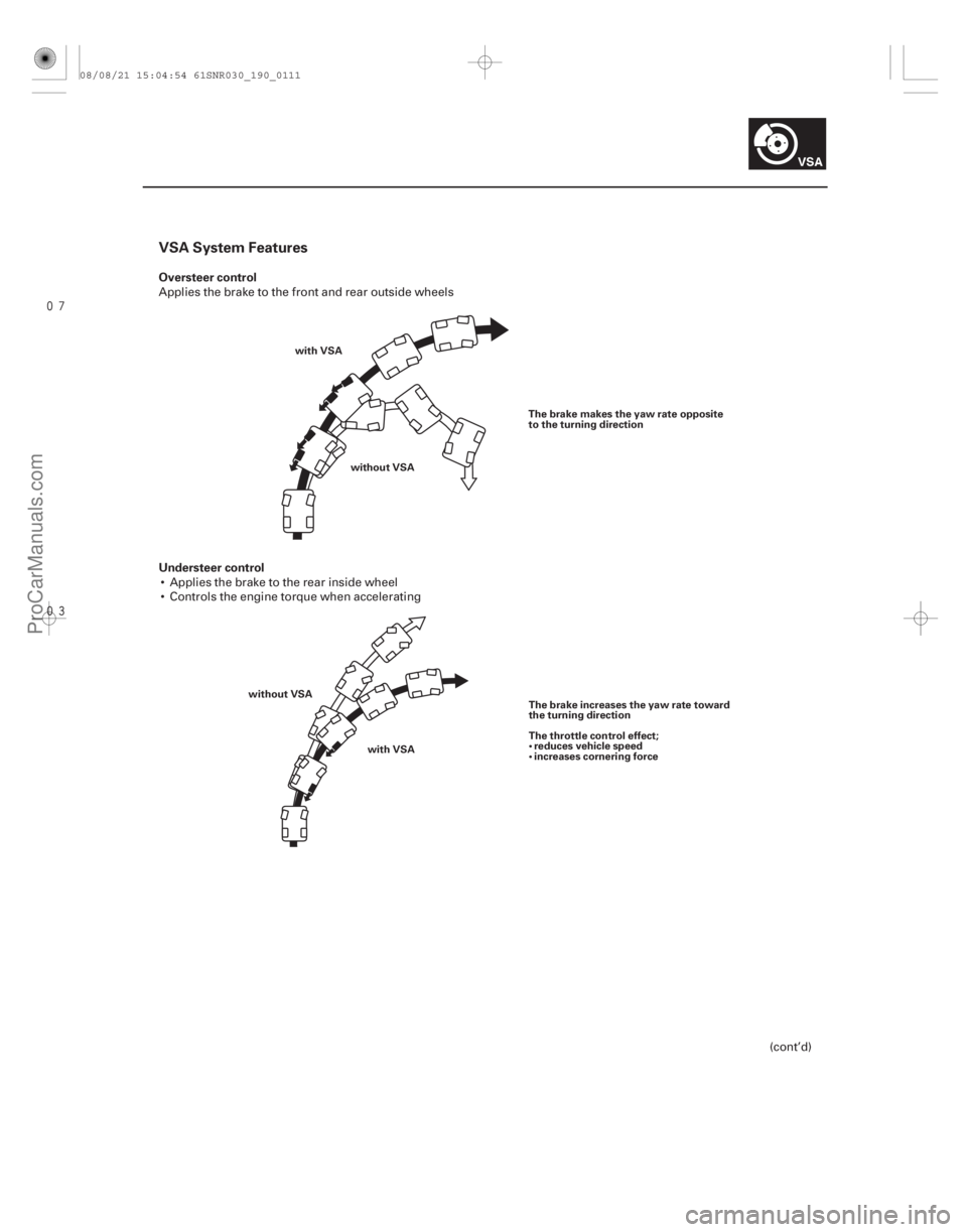
VSA System Features
Oversteer control
Understeer control
19-111
with VSAwithout VSA The brake makes the yaw rate opposite
to the turning direction
with VSA
without VSA
The brake increases the yaw rate toward
the turning direction
The throttle control effect;
reduces vehicle speed
increases cornering force
Applies the brake to the front and rear outside wheels
Applies the brake to the rear inside wheel
Controls the engine torque when accelerating
(cont’d)
08/08/21 15:04:54 61SNR030_190_0111
ProCarManuals.com
DYNOMITE -2009-
Page 1660 of 2893
����
19-168VSA System Components
Steering Angle Sensor Replacement
A
B
C
NOTE: Do not damage or drop the combination switch as the steering angle sens")
���
�(�#�'���������������
���������������
� �����)����
19-168VSA System Components
Steering Angle Sensor Replacement
A
B
C
NOTE: Do not damage or drop the combination switch as the steering angle sensor is sensitive to shock and vibration.
1. With the wheels in the straight-ahead position and the steering wheel centered, remove the steering wheel (see page 17-6).
2. Remove the steering column covers (see page 17-9) and the cable reel (see page 24-200).
3. Remove the combination switch assembly (see step 11 on page 17-11).
4. Remove the combination light switch (A) and the wiper/washer switch (B) from the combination switch body assembly (C).
5. Install the combination switch body assembly in the r everse order of removal.
NOTE: Do not remove the steering angle sensor from the combination switch body.
When installing the cable reel, set the turn signal canceling sleeve position so that the arrow points straight up (see page 24-201).
When installing the combination switch, tighten the m ounting screws to the specified torque and sequence
shown (see page 17-12).
08/08/21 15:06:45 61SNR030_190_0168
ProCarManuals.com
DYNOMITE -2009-