Page 2390 of 5135
Radiator CapRadiator Cap Tester
30� or more
A51912
A36661
Turn 16±28
± COOLINGCOOLING SYSTEM (1AZ±FSE)
AVENSIS REPAIR MANUAL (RM1018E)
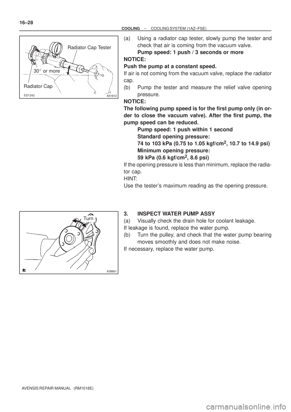
(a) Using a radiator cap tester, slowly pump the tester and
check that air is coming from the vacuum valve.
Pump speed: 1 push / 3 seconds or more
NOTICE:
Push the pump at a constant speed.
If air is not coming from the vacuum valve, replace the radiator
cap.
(b) Pump the tester and measure the relief valve opening
pressure.
NOTICE:
The following pump speed is for the first pump only (in or-
der to close the vacuum valve). After the first pump, the
pump speed can be reduced.
Pump speed: 1 push within 1 second
Standard opening pressure:
74 to 103 kPa (0.75 to 1.05 kgf/cm
2, 10.7 to 14.9 psi)
Minimum opening pressure:
59 kPa (0.6 kgf/cm
2, 8.6 psi)
If the opening pressure is less than minimum, replace the radia-
tor cap.
HINT:
Use the tester's maximum reading as the opening pressure.
3. INSPECT WATER PUMP ASSY
(a) Visually check the drain hole for coolant leakage.
If leakage is found, replace the water pump.
(b) Turn the pulley, and check that the water pump bearing
moves smoothly and does not make noise.
If necessary, replace the water pump.
Page 2391 of 5135
160MY±01
A78433
± COOLINGCOOLING SYSTEM (1AZ±FSE)
16±25
AVENSIS REPAIR MANUAL (RM1018E)
COOLING SYSTEM (1AZ±FSE)
ON±VEHICLE INSPECTION
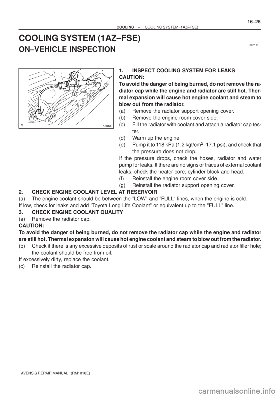
1. INSPECT COOLING SYSTEM FOR LEAKS
CAUTION:
To avoid the danger of being burned, do not remove the ra-
diator cap while the engine and radiator are still hot. Ther-
mal expansion will cause hot engine coolant and steam to
blow out from the radiator.
(a) Remove the radiator support opening cover.
(b) Remove the engine room cover side.
(c) Fill the radiator with coolant and attach a radiator cap tes-
ter.
(d) Warm up the engine.
(e) Pump it to 118 kPa (1.2 kgf/cm
2, 17.1 psi), and check that
the pressure does not drop.
If the pressure drops, check the hoses, radiator and water
pump for leaks. If there are no signs or traces of external coolant
leaks, check the heater core, cylinder block and head.
(f) Reinstall the engine room cover side.
(g) Reinstall the radiator support opening cover.
2. CHECK ENGINE COOLANT LEVEL AT RESERVOIR
(a) The engine coolant should be between the ºLOWº and ºFULLº lines, when the engine is cold.
If low, check for leaks and add ºToyota Long Life Coolantº or equivalent up to the ºFULLº line.
3. CHECK ENGINE COOLANT QUALITY
(a) Remove the radiator cap.
CAUTION:
To avoid the danger of being burned, do not remove the radiator cap while the engine and radiator
are still hot. Thermal expansion will cause hot engine coolant and steam to blow out from the radiator.
(b) Check if there is any excessive deposits of rust or scale around the radiator cap and radiator filler hole;
the coolant should be free from oil.
If excessively dirty, replace the coolant.
(c) Reinstall the radiator cap.
Page 2432 of 5135
190NI±01
A78487
(a)
(d)
(e)
(c)
Terminal Cap No. 2
A78488
A78488
A
B
±
STARTING & CHARGING GENERATOR ASSY(1ZZ±FE/3ZZ±FE)
19±7
AVENSIS REPAIR MANUAL (RM1018E)
GENERATOR ASSY(1ZZ±FE/3ZZ±FE)
REPLACEMENT
1.REMOVE ENGINE UNDER COVER SUB±ASSY NO.1 (See page 10±17)
2.REMOVE RADIATOR SUPPORT OPENING COVER (See page 10±9)
3.REMOVE ENGINE ROOM COVER SIDE (See page 10±9)
4.REMOVE FAN AND GENERATOR V BELT (See page 14±5)
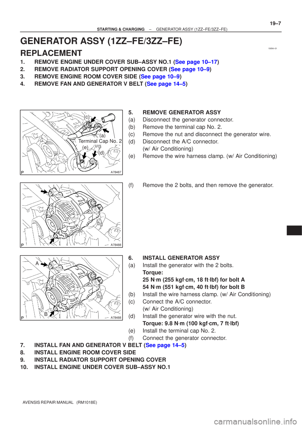
5.REMOVE GENERATOR ASSY
(a)Disconnect the generator connector.
(b)Remove the terminal cap No. 2.
(c)Remove the nut and disconnect the generator wire.
(d)Disconnect the A/C connector. (w/ Air Conditioning)
(e)Remove the wire harness clamp. (w/ Air Conditioning)
(f)Remove the 2 bolts, and then remove the generator.
6.INSTALL GENERATOR ASSY
(a)Install the generator with the 2 bolts. Torque:
25 N�m (255 kgf �cm, 18 ft �lbf) for bolt A
54 N �m (551 kgf �cm, 40 ft �lbf) for bolt B
(b)Install the wire harness clamp. (w/ Air Conditioning)
(c)Connect the A/C connector. (w/ Air Conditioning)
(d)Install the generator wire with the nut. Torque: 9.8 N �m (100 kgf �cm, 7 ft �lbf)
(e)Install the terminal cap No. 2.
(f)Connect the generator connector.
7.INSTALL FAN AND GENERATOR V BELT (See page 14±5)
8. INSTALL ENGINE ROOM COVER SIDE
9. INSTALL RADIATOR SUPPORT OPENING COVER
10. INSTALL ENGINE UNDER COVER SUB±ASSY NO.1
Page 2468 of 5135
190O1±01
A79176
±
STARTING & CHARGING GENERATOR ASSY(1CD±FTV)
19±29
AVENSIS REPAIR MANUAL (RM1018E)
GENERATOR ASSY(1CD±FTV)
REPLACEMENT
1.REMOVE FRONT WHEEL RH
2.REMOVE RADIATOR SUPPORT OPENING COVER
3.REMOVE ENGINE ROOM COVER SIDE
4.REMOVE ENGINE UNDER COVER SUB±ASSY NO.1
5.REMOVE ENGINE UNDER COVER RH
6.REMOVE V (COOLER COMPRESSOR TO CRANKSHAFT PULLEY) BELT NO.1
(See page 14±269)
7.REMOVE GENERATOR V BELT (See page 14±269)
8.REMOVE FLOOR PANEL BRACE FRONT(See page 15±10)
9.REMOVE EXHAUST PIPE ASSY FRONT(See page 15±10)
10.REMOVE EXHAUST PIPE ASSY (W/ COLD AREA) (See page 13±11)
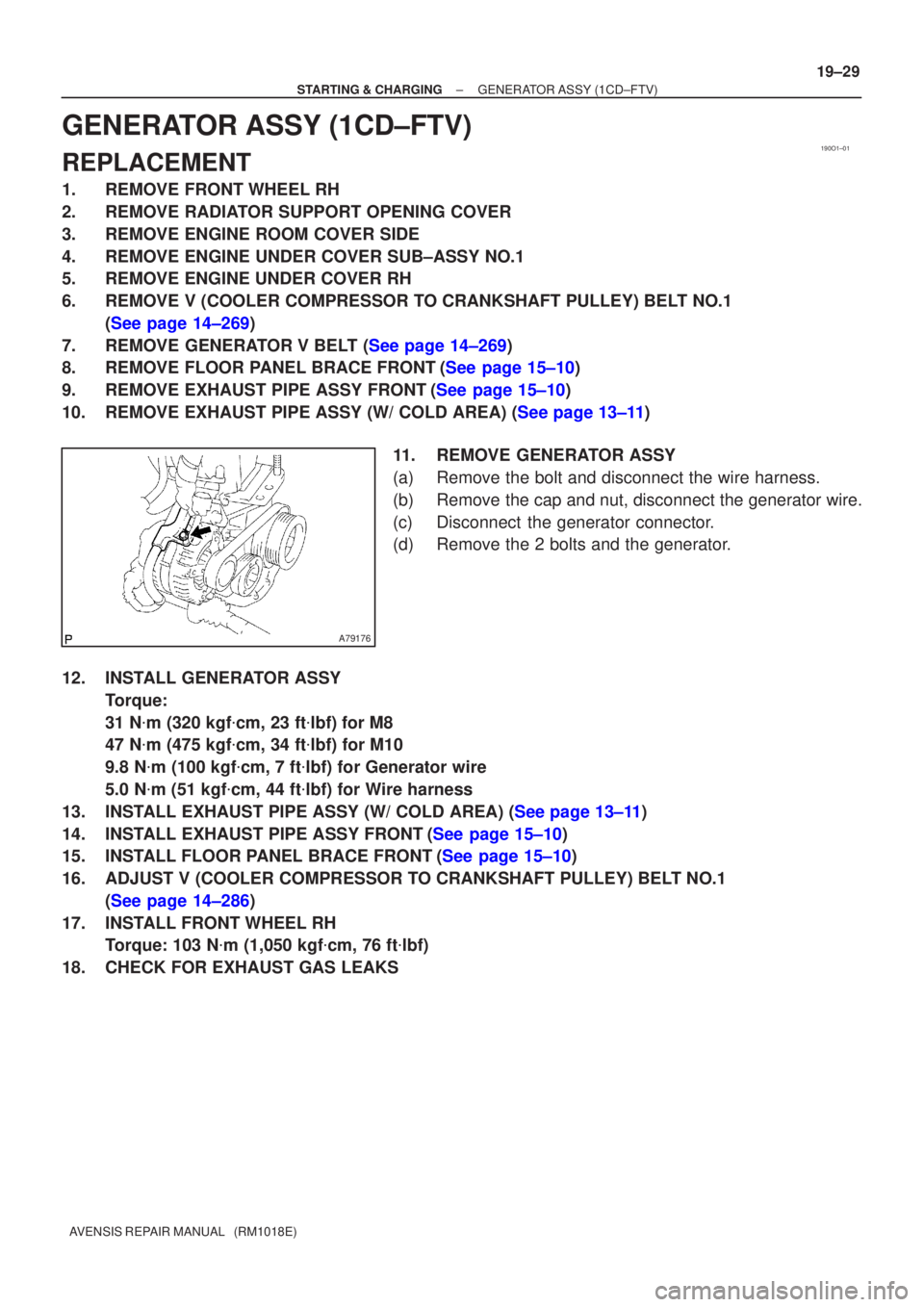
11.REMOVE GENERATOR ASSY
(a)Remove the bolt and disconnect the wire harness.
(b)Remove the cap and nut, disconnect the generator wire.
(c)Disconnect the generator connector.
(d)Remove the 2 bolts and the generator.
12.INSTALL GENERATOR ASSY Torque:
31 N�m (320 kgf �cm, 23 ft �lbf) for M8
47 N �m (475 kgf �cm, 34 ft �lbf) for M10
9.8 N �m (100 kgf �cm, 7 ft �lbf) for Generator wire
5.0 N �m (51 kgf �cm, 44 ft �lbf) for Wire harness
13.INSTALL EXHAUST PIPE ASSY (W/ COLD AREA) (See page 13±11)
14.INSTALL EXHAUST PIPE ASSY FRONT(See page 15±10)
15.INSTALL FLOOR PANEL BRACE FRONT(See page 15±10)
16. ADJUST V (COOLER COMPRESSOR TO CRANKSHAFT PULLEY) BELT NO.1 (See page 14±286)
17. INSTALL FRONT WHEEL RH Torque: 103 N �m (1,050 kgf �cm, 76 ft �lbf)
18. CHECK FOR EXHAUST GAS LEAKS
Page 2476 of 5135
190NK±01
A78515
A78516
A77903
(a)
(a)
(b)
(b)
(b)
A77904
(f)
(f)
(e)
(d)
Terminal Cap
19±20
±
STARTING & CHARGING GENERATOR ASSY(1AZ±FE/1AZ±FSE)
AVENSIS REPAIR MANUAL (RM1018E)
GENERATOR ASSY(1AZ±FE/1AZ±FSE)
REPLACEMENT
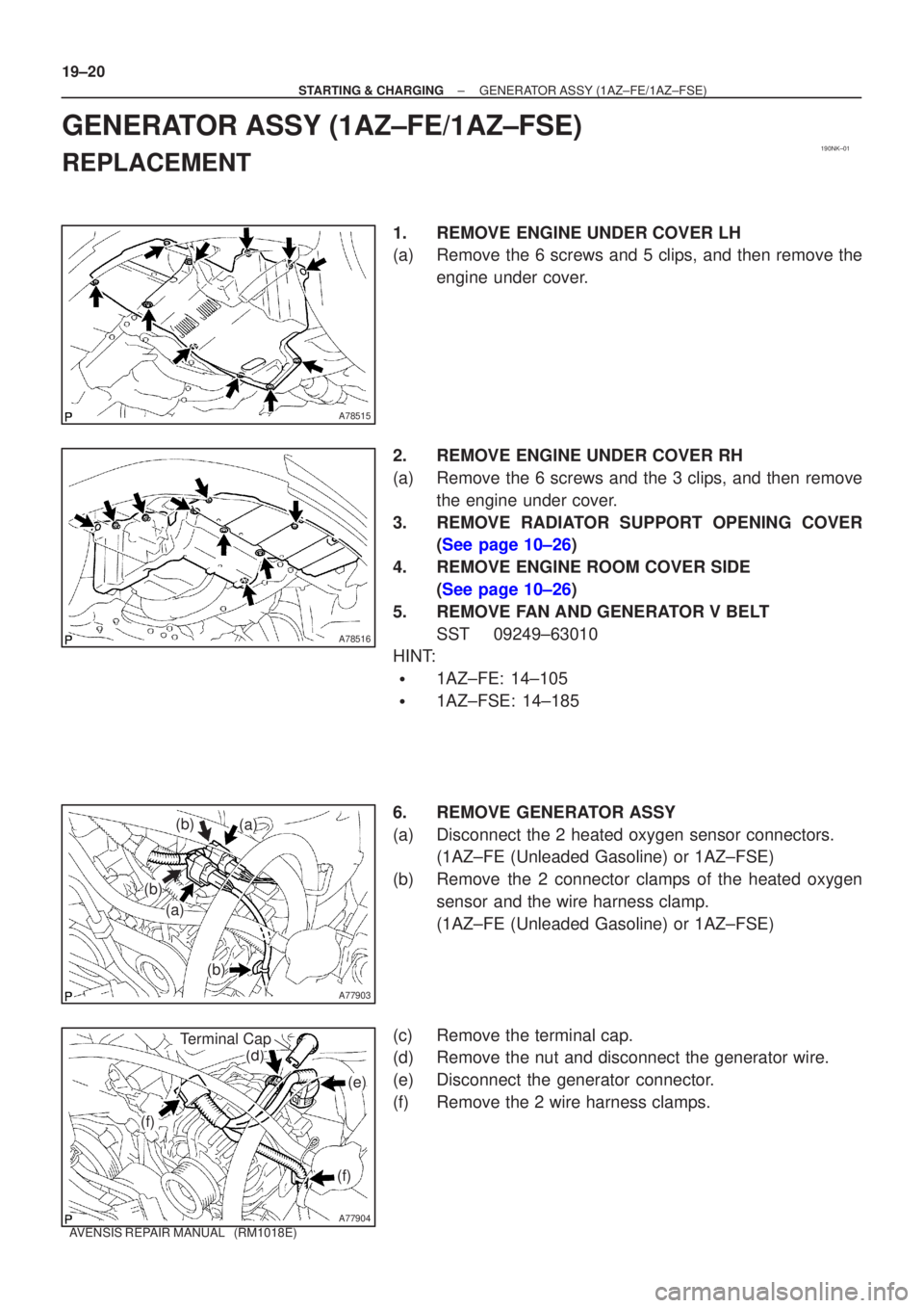
1.REMOVE ENGINE UNDER COVER LH
(a)Remove the 6 screws and 5 clips, and then remove the engine under cover.
2.REMOVE ENGINE UNDER COVER RH
(a)Remove the 6 screws and the 3 clips, and then remove the engine under cover.
3.REMOVE RADIATOR SUPPORT OPENING COVER (See page 10±26)
4. REMOVE ENGINE ROOM COVER SIDE (See page 10±26)
5. REMOVE FAN AND GENERATOR V BELT SST 09249±63010
HINT:
�1AZ±FE: 14±105
�1AZ±FSE: 14±185
6. REMOVE GENERATOR ASSY
(a) Disconnect the 2 heated oxygen sensor connectors. (1AZ±FE (Unleaded Gasoline) or 1AZ±FSE)
(b) Remove the 2 connector clamps of the heated oxygen sensor and the wire harness clamp.
(1AZ±FE (Unleaded Gasoline) or 1AZ±FSE)
(c) Remove the terminal cap.
(d) Remove the nut and disconnect the generator wire.
(e) Disconnect the generator connector.
(f) Remove the 2 wire harness clamps.
Page 2477 of 5135
A77905
A77906
A77905
A
B
± STARTING & CHARGINGGENERATOR ASSY (1AZ±FE/1AZ±FSE)
19±21
AVENSIS REPAIR MANUAL (RM1018E)
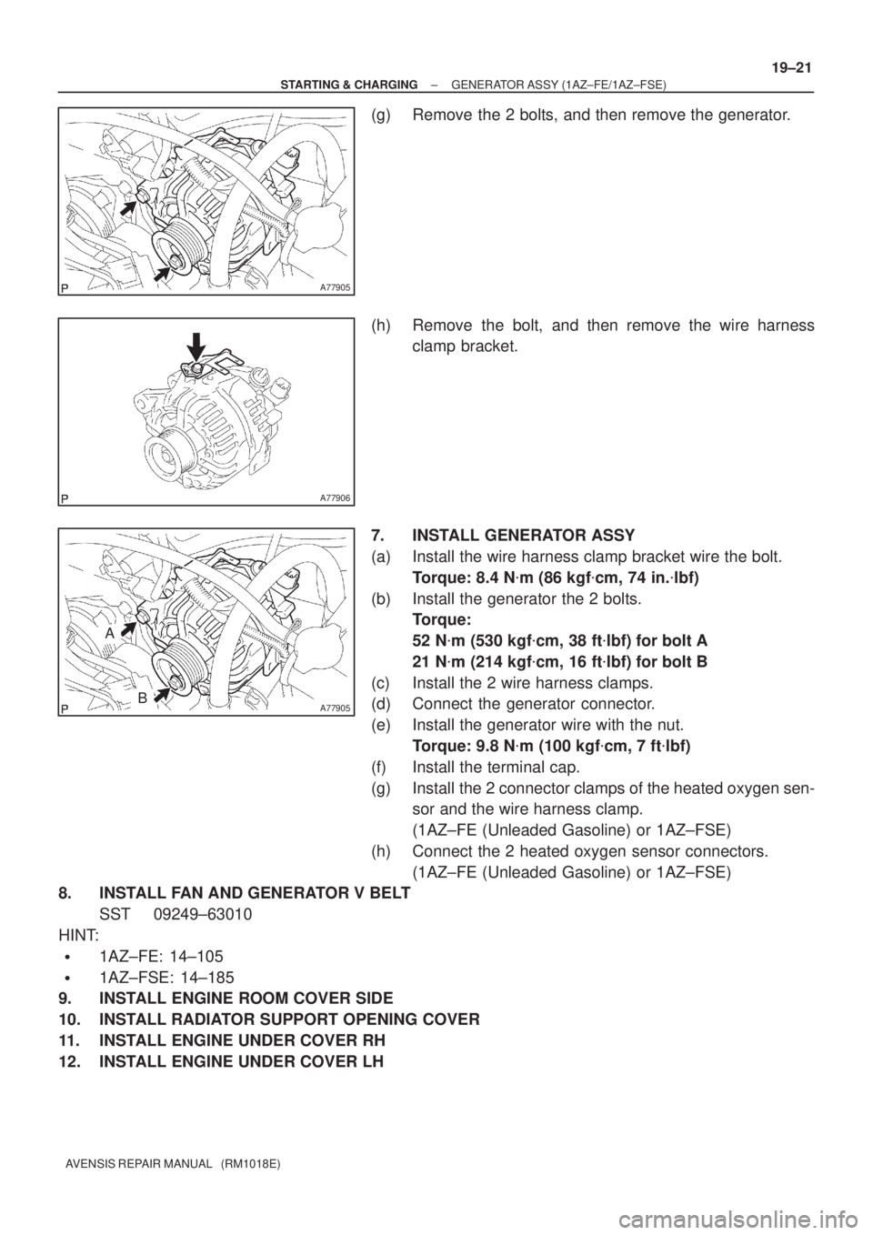
(g) Remove the 2 bolts, and then remove the generator.
(h) Remove the bolt, and then remove the wire harness
clamp bracket.
7. INSTALL GENERATOR ASSY
(a) Install the wire harness clamp bracket wire the bolt.
Torque: 8.4 N�m (86 kgf�cm, 74 in.�lbf)
(b) Install the generator the 2 bolts.
Torque:
52 N�m (530 kgf�cm, 38 ft�lbf) for bolt A
21 N�m (214 kgf�cm, 16 ft�lbf) for bolt B
(c) Install the 2 wire harness clamps.
(d) Connect the generator connector.
(e) Install the generator wire with the nut.
Torque: 9.8 N�m (100 kgf�cm, 7 ft�lbf)
(f) Install the terminal cap.
(g) Install the 2 connector clamps of the heated oxygen sen-
sor and the wire harness clamp.
(1AZ±FE (Unleaded Gasoline) or 1AZ±FSE)
(h) Connect the 2 heated oxygen sensor connectors.
(1AZ±FE (Unleaded Gasoline) or 1AZ±FSE)
8. INSTALL FAN AND GENERATOR V BELT
SST 09249±63010
HINT:
�1AZ±FE: 14±105
�1AZ±FSE: 14±185
9. INSTALL ENGINE ROOM COVER SIDE
10. INSTALL RADIATOR SUPPORT OPENING COVER
11. INSTALL ENGINE UNDER COVER RH
12. INSTALL ENGINE UNDER COVER LH
Page 2484 of 5135
190NJ±01
A77898
A77899
(a)
(a)
(a)(c)
(d)
Terminal Cap Cover
A77900
A77901
19±12
±
STARTING & CHARGING STARTER ASSY(1AZ±FE/1AZ±FSE)
AVENSIS REPAIR MANUAL (RM1018E)
STARTER ASSY(1AZ±FE/1AZ±FSE)
REPLACEMENT
1.REMOVE RADIATOR SUPPORT OPENING COVER (See page 10±26)
2. REMOVE BATTERY CLAMP SUB±ASSY
3. REMOVE BATTERY
4. REMOVE BATTERY TRAY 5. REMOVE BATTERY CARRIER
(a) Remove the 4 bolts, and then remove the battery carrier.
6. REMOVE STARTER ASSY
(a) Remove the 3 wire harness clamps.
(b) Open the terminal cap cover.
(c) Remove the nut and disconnect the starter wire.
(d) Disconnect the starter connector.
(e) Remove the 2 bolts, and then remove the starter.
(f) Remove the bolt, and then remove the wire harnessclamp bracket.
Page 2485 of 5135
± STARTING & CHARGINGSTARTER ASSY (1AZ±FE/1AZ±FSE)
19±13
AVENSIS REPAIR MANUAL (RM1018E)
7. INSTALL STARTER ASSY
(a) Install the wire harness clamp bracket with the bolt.
Torque: 8.4 N�m (86 kgf�cm, 74 in.�lbf)
(b) Install the starter with the 2 bolts.
Torque: 37 N�m (380 kgf�cm, 28 ft�lbf)
(c) Connect the starter connector.
(d) Connect the starter wire with the nut.
Torque: 9.8 N�m (100 kgf�cm, 7 ft�lbf)
(e) Close the terminal cap cover.
(f) Install the 3 wire harness clamps.
8. INSTALL BATTERY CARRIER
Torque: 13 N�m (131 kgf�cm, 9 ft�lbf)
9. INSTALL BATTERY TRAY
10. INSTALL BATTERY
11. INSTALL BATTERY CLAMP SUB±ASSY
Torque:
5.0 N�m (51 kgf�cm, 44 in.�lbf) for bolt
3.6 N�m (36 kgf�cm, 31 in.�lbf) for nut
5.4 N�m (55 kgf�cm, 48 in.�lbf) for terminal
12. INSTALL RADIATOR SUPPORT OPENING COVER