Page 4613 of 5135
−
ENGINE CONTROL SYSTEM KNOCK SENSOR (2AZ−FSE)
10 −17
AVENSIS Supplement (RM1045E)
25. INSTALL FUEL PUMP ASSY (See page 11 −24)
26. INSTALL FUEL PIPE SUB −ASSY NO.1 (See page 11 −24)
SST 09023 −12900
27. INSTALL FUEL HOSE
28. INSTALL FUEL TUBE SUB −ASSY (See page 11 −24)
SST 09617 −24011
29. INSTALL THROTTLE BODY ASSY (See page 10 −8)
30. INSTALL AIR CLEANER CAP SUB −ASSY (See page 10 −8)
31. CONNECT ENGINE WIRE NO.3 (BATTERY NEGATIVE TERMINAL) Torque: 5.4 N �m (55 kgf �cm, 48 in. �lbf)
32. ADD ENGINE COOLANT (See page 16 −7)
33. CHECK FOR ENGINE COOLANT LEAKS (See page 16 −1)
34. CHECK FOR FUEL LEAKS (See page 11 −4)
35. CHECK FOR ENGINE OIL LEAKS
36. INSTALL ENGINE COVER SUB −ASSY NO.1 ( See page 10 −8)
37. INSTALL ENGINE ROOM COVER SIDE
38. INSTALL RADIATOR SUPPORT OPENING COVER
Page 4634 of 5135
141NJ−01
A85615
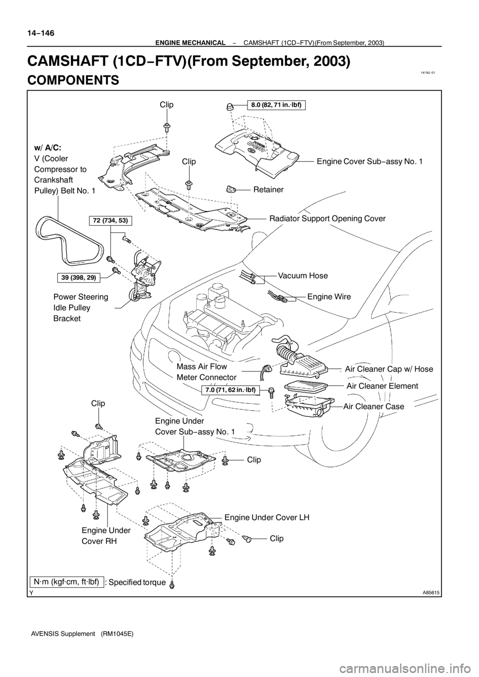
Engine Cover Sub−assy No. 1
Radiator Support Opening Cover
Clip
Clip
Retainer
8.0 (82, 71 in.�lbf)
w/ A/C:
V (Cooler
Compressor to
Crankshaft
Pulley) Belt No. 1
72 (734, 53)
39 (398, 29)
Power Steering
Idle Pulley
Bracket
Clip
N·m (kgf·cm, ft·lbf)
: Specified torque Engine Under
Cover RH
Engine Under
Cover Sub−assy No. 1
Clip
Engine Under Cover LH
Clip
Air Cleaner Cap w/ Hose
Air Cleaner Element
Air Cleaner Case
7.0 (71, 62 in.�lbf)
Mass Air Flow
Meter Connector
Engine Wire Vacuum Hose
14−146
− ENGINE MECHANICALCAMSHAFT (1CD−FTV)(From September, 2003)
AVENSIS Supplement (RM1045E)
CAMSHAFT (1CD−FTV)(From September, 2003)
COMPONENTS
Page 4649 of 5135

(a)
(b)(b)
(a)
A84286
14 −108−
ENGINE MECHANICAL PARTIAL ENGINE ASSY (1CD −FTV)(From September,
2003)
AVENSIS Supplement (RM1045E)
REPLACEMENT
1. REMOVE FRONT WHEELS
2. REM")
141NG−01
A84393
(a)
(a)
(b)(b)
(a)
A84286
14 −108−
ENGINE MECHANICAL PARTIAL ENGINE ASSY (1CD −FTV)(From September,
2003)
AVENSIS Supplement (RM1045E)
REPLACEMENT
1. REMOVE FRONT WHEELS
2. REMOVE ENGINE UNDER COVER LH
3. REMOVE ENGINE UNDER COVER SUB −ASSY NO.1
4. REMOVE ENGINE UNDER COVER RH
5. REMOVE RADIATOR SUPPORT OPENING COVER
6. REMOVE ENGINE ROOM COVER SIDE
7. DRAIN ENGINE COOLANT (See page 16 −19)
8. DRAIN ENGINE OIL (See Pub No. RM1018E on page 17 −30)
9. DRAIN MANUAL TRANSAXLE OIL
Torque: 49 N �m (500 kgf �cm, 36 ft �lbf)
10. REMOVE ENGINE COVER SUB −ASSY NO.1
(a) Remove the 5 nuts, then remove the engine cover.
11. REMOVE BATTERY
12. REMOVE AIR CLEANER ASSY
(a) Disconnect the mass air flow meter connector.
(b) Remove the air cleaner cap together with the air cleaner hose.
(c) Remove the air cleaner filter element.
(d) Remove the 3 bolts and air cleaner case.
13. REMOVE VACUUM RESERVOIR SUB −ASSY
(a) Disconnect the 2 vacuum hoses and connector.
(b) Remove the 2 bolts and vacuum reservoir.
14. REMOVE FUEL FILTER ASSY (See Pub. No. RM1018E on page 11 −82)
15. REMOVE RADIATOR HOSE INLET
16. REMOVE RADIATOR HOSE OUTLET
17. DISCONNECT WATER BY−PASS HOSE NO.2
Page 4699 of 5135
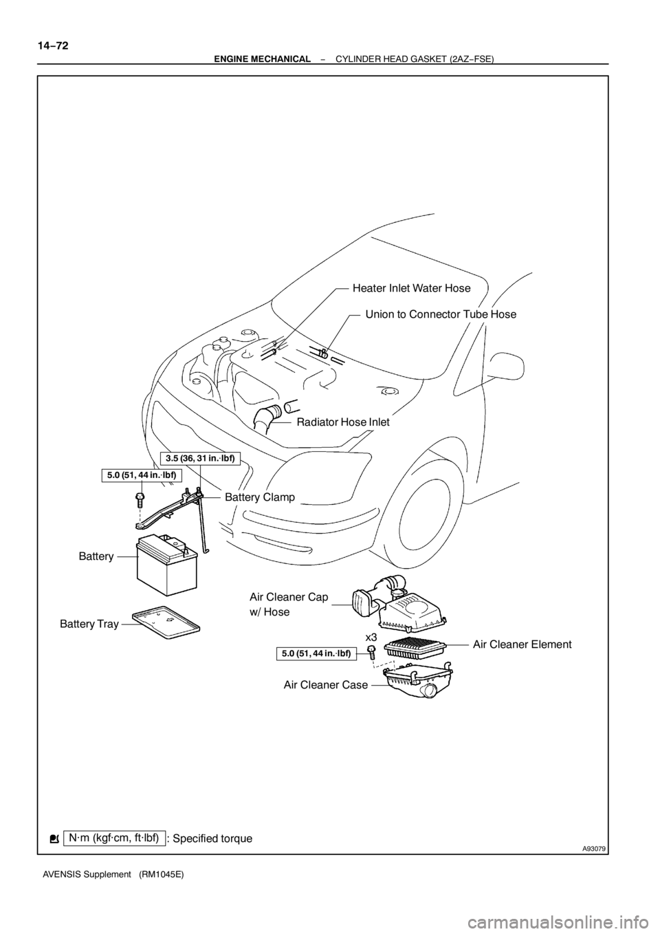
A93079
Air Cleaner Cap
w/ Hose
Air Cleaner Element
5.0 (51, 44 in.�lbf)
Battery Tray
Battery
Battery Clamp
Heater Inlet Water Hose
Union to Connector Tube Hose
N·m (kgf·cm, ft·lbf)
: Specified torque
5.0 (51, 44 in.�lbf)
Air Cleaner Case
Radiator Hose Inlet
x3
3.5 (36, 31 in.�lbf)
14−72
− ENGINE MECHANICALCYLINDER HEAD GASKET (2AZ−FSE)
AVENSIS Supplement (RM1045E)
Page 4707 of 5135
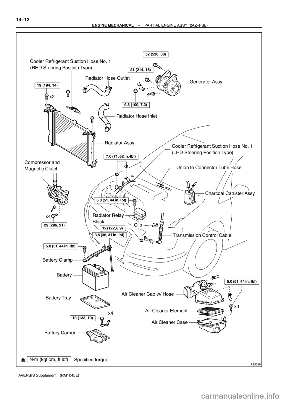
A93086N·m (kgf·cm, ft·lbf)
: Specified torque
19 (194, 14)
Air Cleaner Cap w/ Hose
Air Cleaner Element
Air Cleaner Case
Battery Carrier
5.0 (51, 44 in.�lbf)
29 (296, 21)
x4
52 (530, 38)
21 (214, 16)
5.0 (51, 44 in.�lbf)
13 (133, 10)x4
Battery Tray
Battery
Battery Clamp
12 (122, 8.9)
Radiator Relay
Block
Clip
Transmission Control Cable
7.0 (71, 62 in.�lbf)
Compressor and
Magnetic Clutch
Generator Assy
9.8 (100, 7.2)
Radiator Assy
Radiator Hose Inlet
Cooler Refrigerant Suction Hose No. 1
(LHD Steering Position Type)
Union to Connector Tube Hose
Charcoal Canister Assy
x2Radiator Hose Outlet
Cooler Refrigerant Suction Hose No. 1
(RHD Steering Position Type)
3.5 (36, 31 in.�lbf)
5.0 (51, 44 in.�lbf)
x3
14−12
− ENGINE MECHANICALPARTIAL ENGINE ASSY (2AZ−FSE)
AVENSIS Supplement (RM1045E)
Page 4718 of 5135

(b)
(a)
(a)
(b)
A93661
(a)
(a) (a)
(a) (b)
(a)
(b)
13
−12
−
INTAKE TURBOCHARGER SUB −ASSY (1CD −FTV)(From
September, 2003)
AVENSIS Supplement (RM1045E)
REPLACEMENT
1. RE")
1308N−01
A84393
(a)
(b)
(a)
(a)
(b)
A93661
(a)
(a) (a)
(a) (b)
(a)
(b)
13
−12
−
INTAKE TURBOCHARGER SUB −ASSY (1CD −FTV)(From
September, 2003)
AVENSIS Supplement (RM1045E)
REPLACEMENT
1. REMOVE ENGINE UNDER COVER SUB −ASSY NO.1
2. DRAIN ENGINE COOLANT (See page 16 −19)
3. REMOVE RADIATOR SUPPORT OPENING COVER
4. REMOVE ENGINE COVER SUB −ASSY NO.1
(a) Remove the 5 nuts and engine cover.
5. REMOVE VACUUM RESERVOIR SUB −ASSY
(a) Disconnect the 2 vacuum hoses and connector.
(b) Remove the 2 bolts and vacuum reservoir.
6. REMOVE DIFFERENTIAL PRESSURE SENSOR ASSY (See page 14 −108)
7. DISCONNECT ENGINE WIRE (See page 14 −138)
8. REMOVE AIR CLEANER ASSY
(a) Disconnect the PCV hose and connector.
(b) Remove the air cleaner cap with the air cleaner hose.
(c) Remove the air cleaner filter element.
(d) Remove the 3 bolts and air cleaner case.
9. REMOVE AIR TUBE NO.1
(a) Remove the 3 bolts and nut, then separate the air tubeNo. 1.
(b) Loosen the hose clamp bolts.
10. REMOVE FUEL FILTER ASSY (See Pub. No. RM1018E on page 11 −82)

10 −17
AVENSIS Supplement (RM1045E)
25. INSTALL FUEL PUMP ASSY (See page 11 −24)
26. INSTALL FUEL PIPE SUB −ASSY NO.1 (See page 11 −24)
SST")