Page 3739 of 5135
4103Z±01
C83559
C83560
Matchmarks
C83561
C83562
41±78
±
MANUAL TRANSMISSION/TRANSAXLE DIFFERENTIAL CASE ASSY (E355/E356)
E355,E356 M/T REPAIR MANUAL (RM867E)
DIFFERENTIAL CASE ASSY (E355/E356)
OVERHAUL
HINT:
COMPONENTS: See page 41±1 1. REMOVE SPEEDOMETER DRIVE (MTM) GEAR
(a) Remove the speedometer drive (MTM) gear from front dif-ferential case assy.
2. REMOVE FRONT DIFFERENTIAL RING GEAR
(a) Place machmarks on the from the front differential ring gear and from the front differential case.
(b) Remove the 16 bolts. using a plastic hammer, remove the front differential case.
3. INSPECT FRONT DIFFERENTIAL SIDE GEAR BACKLASH
(a) Fixing the front differential pinion to the front differential
case side. Using a dial indicator, measure the front differ-
ential side gear backlash.
Standard backlash: 0.05 ± 0.2 mm (0.0020 ± 0.0079 in.)
Page 3740 of 5135

SST
C83563
C83564
C83565
C83566
C68517
± MANUAL TRANSMISSION/TRANSAXLEDIFFERENTIAL CASE ASSY (E355/E356)
41±79
E355,E356 M/T REPAIR MANUAL (RM867E)
4. REMOVE FRONT DIFFERENTIAL PINION SHAFT
STRAIGHT PIN
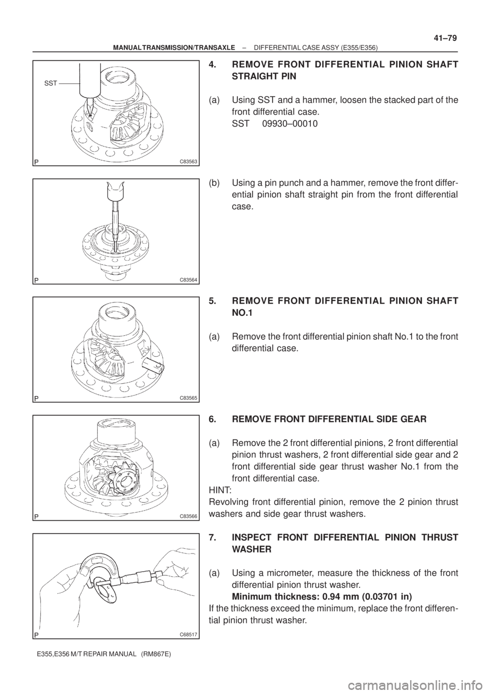
(a) Using SST and a hammer, loosen the stacked part of the
front differential case.
SST 09930±00010
(b) Using a pin punch and a hammer, remove the front differ-
ential pinion shaft straight pin from the front differential
case.
5. REMOVE FRONT DIFFERENTIAL PINION SHAFT
NO.1
(a) Remove the front differential pinion shaft No.1 to the front
differential case.
6. REMOVE FRONT DIFFERENTIAL SIDE GEAR
(a) Remove the 2 front differential pinions, 2 front differential
pinion thrust washers, 2 front differential side gear and 2
front differential side gear thrust washer No.1 from the
front differential case.
HINT:
Revolving front differential pinion, remove the 2 pinion thrust
washers and side gear thrust washers.
7. INSPECT FRONT DIFFERENTIAL PINION THRUST
WASHER
(a) Using a micrometer, measure the thickness of the front
differential pinion thrust washer.
Minimum thickness: 0.94 mm (0.03701 in)
If the thickness exceed the minimum, replace the front differen-
tial pinion thrust washer.
Page 3741 of 5135

C68518
C83566
C83565
C83567
41±80
± MANUAL TRANSMISSION/TRANSAXLEDIFFERENTIAL CASE ASSY (E355/E356)
E355,E356 M/T REPAIR MANUAL (RM867E)
8. INSPECT FRONT DIFFERENTIAL PINION SHAFT
NO.1
(a) Using a micrometer, measure the outer diameter of the
front differential pinion shaft No.1.
9. INSTALL FRONT DIFFERENTIAL SIDE GEAR
(a) Coat the rotating surface of the front differential side gear
with gear oil.
(b) Install the 2 front differential side gear thrust washers to
the 2 front differential side gears.
HINT:
(c) Install the 2 front differential side gears, 2 front differential
pinions and front differential thrust washers to the front
differential case.
HINT:
Revolving the front differential pinion, install the 2 front differen-
tial pinions with front differential washers.
10. INSTALL FRONT DIFFERENTIAL PINION SHAFT NO.1
(a) Coat the rotating surface of the front differential pinion
shaft No.1 with gear oil.
(b) Install the front differential pinion shaft No.1 to the front
differential case so that the hole for the front differential
pinion shaft straight pin is aliened with the hole in the front
differential case.
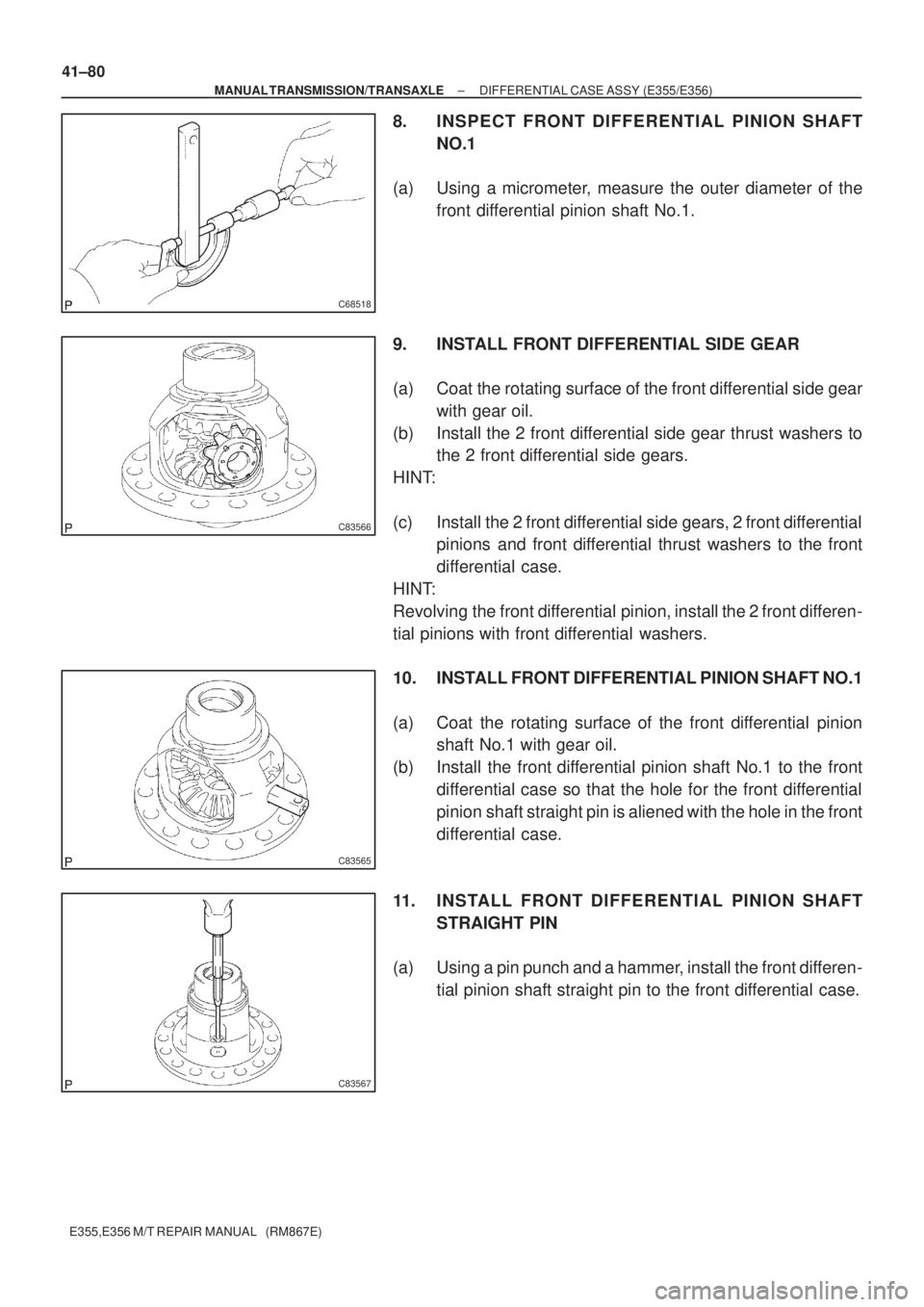
11. INSTALL FRONT DIFFERENTIAL PINION SHAFT
STRAIGHT PIN
(a) Using a pin punch and a hammer, install the front differen-
tial pinion shaft straight pin to the front differential case.
Page 3742 of 5135

C83562
90�11 0�
C58905
C70796
Machmarks
C70795
± MANUAL TRANSMISSION/TRANSAXLEDIFFERENTIAL CASE ASSY (E355/E356)
41±81
E355,E356 M/T REPAIR MANUAL (RM867E)
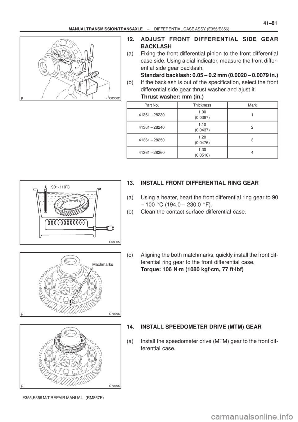
12. ADJUST FRONT DIFFERENTIAL SIDE GEAR
BACKLASH
(a) Fixing the front differential pinion to the front differential
case side. Using a dial indicator, measure the front differ-
ential side gear backlash.
Standard backlash: 0.05 ± 0.2 mm (0.0020 ± 0.0079 in.)
(b) If the backlash is out of the specification, select the front
differential side gear thrust washer and ajust it.
Thrust washer: mm (in.)
Part No.ThicknessMark
41361 ± 282301.00
(0.0397)1
41361 ± 282401.10
(0.0437)2
41361 ± 282501.20
(0.0476)3
41361 ± 282601.30
(0.0516)4
13. INSTALL FRONT DIFFERENTIAL RING GEAR
(a) Using a heater, heart the front differential ring gear to 90
± 100 �C (194.0 ± 230.0 �F).
(b) Clean the contact surface differential case.
(c) Aligning the both matchmarks, quickly install the front dif-
ferential ring gear to the front differential case.
Torque: 106 N�m (1080 kgf�cm, 77 ft�lbf)
14. INSTALL SPEEDOMETER DRIVE (MTM) GEAR
(a) Install the speedometer drive (MTM) gear to the front dif-
ferential case.
Page 3743 of 5135
41041±01
C69529
C69530
C69532
C69799
41±72
±
MANUAL TRANSMISSION/TRANSAXLE SHIFT & SELECT LEVER SHAFT ASSY (E355/E356)
E355,E356 M/T REPAIR MANUAL (RM867E)
SHIFT & SELECT LEVER SHAFT ASSY (E355/E356)
OVERHAUL
HINT:
COMPONENTS: See page 41±1 1. REMOVE CONTROL SHIFT LEVER BUSH
(a) Remove the control shift lever bush from the selectingbellcrank No.2.
2. REMOVE SELECTING BELLCRANK DUST COVER NO.1
(a) Remove the selecting bellcrank dust cover No.1 from the selecting bellcrank No.2.
3. REMOVE SELECTING BELLCRANK SUPPORT SUB±ASSY
(a) Remove the nut, washer and selecting bell crank No.2 plate washer from the selecting bellcrank No.2.
(b) Remove the selecting bellcrank support sub±assy from the selecting bell crank No.2.
Page 3744 of 5135

C69531
C69798
C69534
C69535
± MANUAL TRANSMISSION/TRANSAXLESHIFT & SELECT LEVER SHAFT ASSY (E355/E356)
41±73
E355,E356 M/T REPAIR MANUAL (RM867E)
4. REMOVE SELECTING BELLCRANK DUST COVER
NO.2
(a) Remove the selecting bell crank dust cover No.2 from the
selecting bellcrank no.2.
5. REMOVE SELECTING BELLCRANK NO.2 BUSH
(a) Remove the selecting bellcrank bush from the selecting
bellcrank No.2.
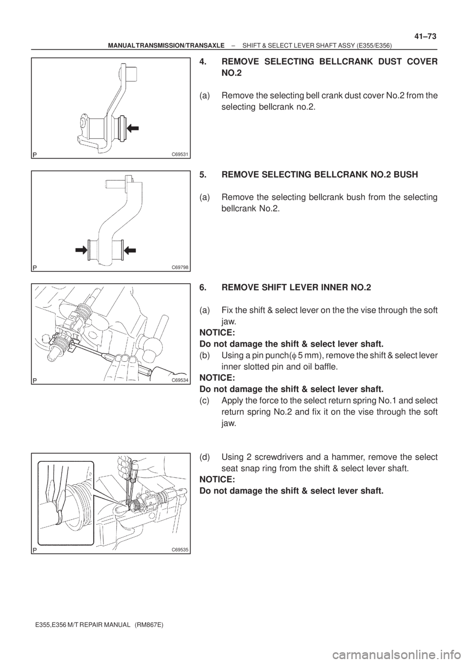
6. REMOVE SHIFT LEVER INNER NO.2
(a) Fix the shift & select lever on the the vise through the soft
jaw.
NOTICE:
Do not damage the shift & select lever shaft.
(b) Using a pin punch(� 5 mm), remove the shift & select lever
inner slotted pin and oil baffle.
NOTICE:
Do not damage the shift & select lever shaft.
(c) Apply the force to the select return spring No.1 and select
return spring No.2 and fix it on the vise through the soft
jaw.
(d) Using 2 screwdrivers and a hammer, remove the select
seat snap ring from the shift & select lever shaft.
NOTICE:
Do not damage the shift & select lever shaft.
Page 3745 of 5135
C68317
C69538
C91167
Shift inter
lock plate
cover
C91169
Shift lever
inner No.1
C69539
41±74
± MANUAL TRANSMISSION/TRANSAXLESHIFT & SELECT LEVER SHAFT ASSY (E355/E356)
E355,E356 M/T REPAIR MANUAL (RM867E)
7. REMOVE SELECT SPRING SEAT NO.1
(a) Using a pin punch(� 5 mm), remove the shift inner lever
slotted pin from the shift & select lever shaft.
(b) Remove the shift lever assy select return spring No.1 and
select spring seat from the shift & select lever shaft.
8. REMOVE SHIFT INTER LOCK PLATE COVER
(a) Remove the shift inter lock plate cover from the shift inter
lock plate.
9. REMOVE SHIFT LEVER INNER NO.1
(a) Remove the shift lever inner No.1 from the shift inter lock
plate.
10. REMOVE SELECT SPRING NO.1 SEAT SHAFT SNAP
RING
(a) Using 2 screwdrivers and a hammer, remove the select
spring No.1 seat shaft snap ring.
NOTICE:
Do not damage the shaft.
Page 3746 of 5135
C69540
C91169
Shift lever inner No.1
C91167
Shift inter lock plate cover
C69538
C69541
± MANUAL TRANSMISSION/TRANSAXLESHIFT & SELECT LEVER SHAFT ASSY (E355/E356)
41±75
E355,E356 M/T REPAIR MANUAL (RM867E)
11. INSTALL SELECT SPRING NO.1 SEAT SHAFT SNAP
RING
(a) Using a brass bar and a hammer, install the select spring
No.1 seat shaft snap ring.
12. INSTALL SHIFT LEVER INNER NO.1
(a) Install the shift lever inner No.1 to the shift inter lock plate.
13. INSTALL SHIFT INTER LOCK PLATE COVER
(a) Install the shift inter lock plate cover to the shift inter lock
plate.
14. INSTALL SELECT SPRING SEAT NO.1
(a) Install the select spring seat No.1, select return spring
No.1 and shift lever inner assy to the shift & select lever
shaft.
(b) Fix the shift & select lever on the vise through the soft jaw.
(c) Using a pin punch(� 5 mm), install the shift lever slotted
pin to the shift & select lever shaft.
Clearance:±0.5 ± 0.5 mm (± 0.0199 ± 0.0199 in.)