Page 3755 of 5135

C70507
C69671
C69672
SST
C69674
± MANUAL TRANSMISSION/TRANSAXLEOUTPUT SHAFT ASSY (E355/E356)
41±67
E355,E356 M/T REPAIR MANUAL (RM867E)
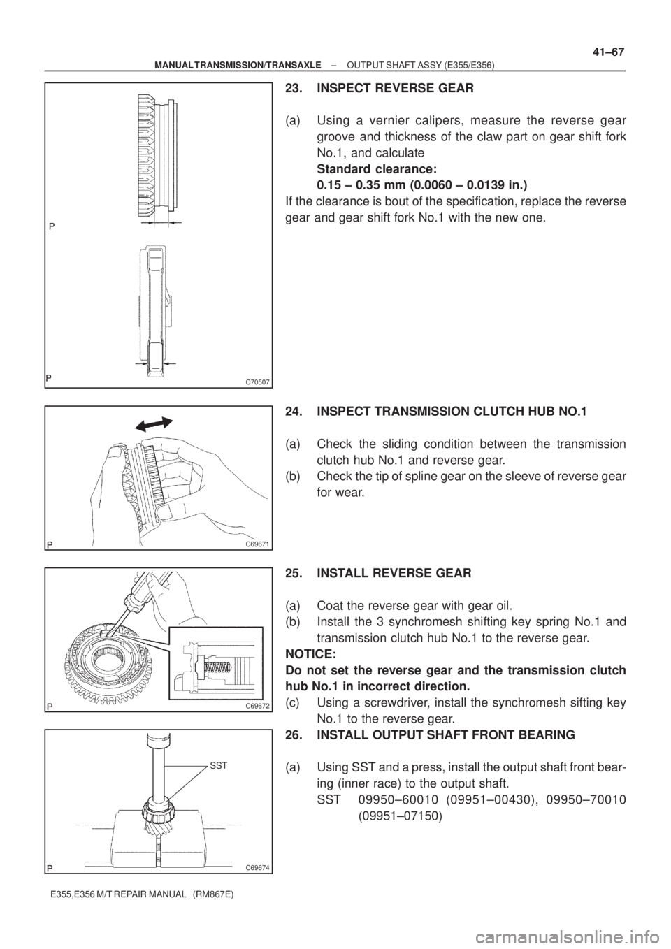
23. INSPECT REVERSE GEAR
(a) Using a vernier calipers, measure the reverse gear
groove and thickness of the claw part on gear shift fork
No.1, and calculate
Standard clearance:
0.15 ± 0.35 mm (0.0060 ± 0.0139 in.)
If the clearance is bout of the specification, replace the reverse
gear and gear shift fork No.1 with the new one.
24. INSPECT TRANSMISSION CLUTCH HUB NO.1
(a) Check the sliding condition between the transmission
clutch hub No.1 and reverse gear.
(b) Check the tip of spline gear on the sleeve of reverse gear
for wear.
25. INSTALL REVERSE GEAR
(a) Coat the reverse gear with gear oil.
(b) Install the 3 synchromesh shifting key spring No.1 and
transmission clutch hub No.1 to the reverse gear.
NOTICE:
Do not set the reverse gear and the transmission clutch
hub No.1 in incorrect direction.
(c) Using a screwdriver, install the synchromesh sifting key
No.1 to the reverse gear.
26. INSTALL OUTPUT SHAFT FRONT BEARING
(a) Using SST and a press, install the output shaft front bear-
ing (inner race) to the output shaft.
SST 09950±60010 (09951±00430), 09950±70010
(09951±07150)
Page 3756 of 5135

C69649
C69650
C69673
SST
SST
C69675
C83814
41±68
± MANUAL TRANSMISSION/TRANSAXLEOUTPUT SHAFT ASSY (E355/E356)
E355,E356 M/T REPAIR MANUAL (RM867E)
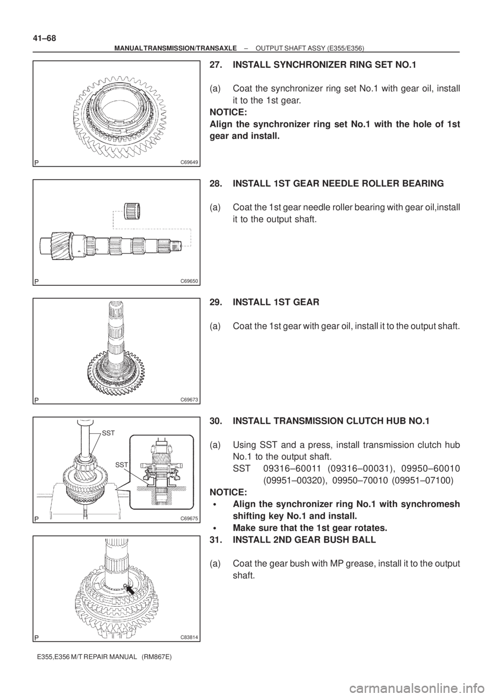
27. INSTALL SYNCHRONIZER RING SET NO.1
(a) Coat the synchronizer ring set No.1 with gear oil, install
it to the 1st gear.
NOTICE:
Align the synchronizer ring set No.1 with the hole of 1st
gear and install.
28. INSTALL 1ST GEAR NEEDLE ROLLER BEARING
(a) Coat the 1st gear needle roller bearing with gear oil,install
it to the output shaft.
29. INSTALL 1ST GEAR
(a) Coat the 1st gear with gear oil, install it to the output shaft.
30. INSTALL TRANSMISSION CLUTCH HUB NO.1
(a) Using SST and a press, install transmission clutch hub
No.1 to the output shaft.
SST 09316±60011 (09316±00031), 09950±60010
(09951±00320), 09950±70010 (09951±07100)
NOTICE:
�Align the synchronizer ring No.1 with synchromesh
shifting key No.1 and install.
�Make sure that the 1st gear rotates.
31. INSTALL 2ND GEAR BUSH BALL
(a) Coat the gear bush with MP grease, install it to the output
shaft.
Page 3757 of 5135
C69646
C69645
C69644
C69643
C69679
± MANUAL TRANSMISSION/TRANSAXLEOUTPUT SHAFT ASSY (E355/E356)
41±69
E355,E356 M/T REPAIR MANUAL (RM867E)
32. INSTALL 2ND GEAR BUSH
(a) Coat the gear 2nd gear bush with gear oil, install it to the
output shaft.
33. INSTALL 2ND GEAR BEARING SPACER
(a) Coat the gear 2nd gear bearing spacer with gear oil,
install it to the output shaft.
34. INSTALL 2ND GEAR NEEDLE ROLLER BEARING
(a) Coat the 2nd gear needle roller bearing with gear oil,
install it to the output shaft.
35. INSTALL SYNCHRONIZER RING SET NO.2
(a) Coat the synchronizer ring set No.2 with gear oil, install
it to the transmission clutch hub No.1
NOTICE:
Align the key groove on the synchronizer ring set No.2 with
the synchromesh shifting key No.1.
36. INSTALL 2ND GEAR
(a) Coat the 2nd gear with gear oil, install it to the output
shaft.
Page 3758 of 5135
SST
SST
C69676
C69641
SST
SST
C69677
SST
SST
C69678
41±70
± MANUAL TRANSMISSION/TRANSAXLEOUTPUT SHAFT ASSY (E355/E356)
E355,E356 M/T REPAIR MANUAL (RM867E)
37. INSTALL 3RD DRIVEN GEAR
(a) Using SST and a press, install the 3rd driven gear to the
output shaft.
SST 09608±00071, 09950±60010 (09951±00320),
09950±70010 (09951±07100)
38. INSTALL OUTPUT GEAR SPACER
(a) install the output gear spacer to the output shaft.
39. INSTALL 4TH DRIVEN GEAR
(a) Using SST and a press, install the 4th driven gear to the
output shaft.
SST 09608±00071, 09950±60010 (09951±00320),
09950±70010 (09951±07100)
40. INSTALL OUTPUT SHAFT FRONT BEARING
(a) Using SST and a press, install the output shaft front bear-
ing (inner race) to the output shaft.
SST 09506±30012, 09950±60010 (09951±00320),
09950±70010 (09951±07100)
Page 3759 of 5135

C69639
C69638
C69637
C69636
± MANUAL TRANSMISSION/TRANSAXLEOUTPUT SHAFT ASSY (E355/E356)
41±71
E355,E356 M/T REPAIR MANUAL (RM867E)
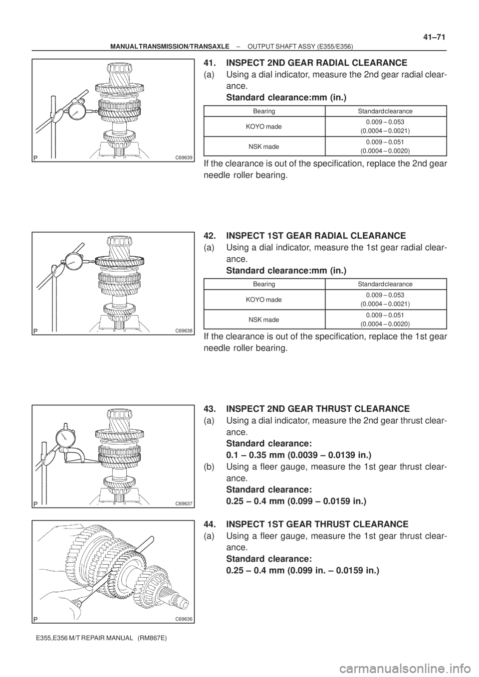
41. INSPECT 2ND GEAR RADIAL CLEARANCE
(a) Using a dial indicator, measure the 2nd gear radial clear-
ance.
Standard clearance:mm (in.)
BearingStandard clearance
KOYO made0.009 ± 0.053
(0.0004 ± 0.0021)
NSK made0.009 ± 0.051
(0.0004 ± 0.0020)
If the clearance is out of the specification, replace the 2nd gear
needle roller bearing.
42. INSPECT 1ST GEAR RADIAL CLEARANCE
(a) Using a dial indicator, measure the 1st gear radial clear-
ance.
Standard clearance:mm (in.)
BearingStandard clearance
KOYO made0.009 ± 0.053
(0.0004 ± 0.0021)
NSK made0.009 ± 0.051
(0.0004 ± 0.0020)
If the clearance is out of the specification, replace the 1st gear
needle roller bearing.
43. INSPECT 2ND GEAR THRUST CLEARANCE
(a) Using a dial indicator, measure the 2nd gear thrust clear-
ance.
Standard clearance:
0.1 ± 0.35 mm (0.0039 ± 0.0139 in.)
(b) Using a fleer gauge, measure the 1st gear thrust clear-
ance.
Standard clearance:
0.25 ± 0.4 mm (0.099 ± 0.0159 in.)
44. INSPECT 1ST GEAR THRUST CLEARANCE
(a) Using a fleer gauge, measure the 1st gear thrust clear-
ance.
Standard clearance:
0.25 ± 0.4 mm (0.099 in. ± 0.0159 in.)
Page 3760 of 5135
4103X±01
C69546
C69637
C69548
41±50
±
MANUAL TRANSMISSION/TRANSAXLE INPUT SHAFT ASSY (E355/E356)
E355,E356 M/T REPAIR MANUAL (RM867E)
INPUT SHAFT ASSY (E355/E356)
OVERHAUL
HINT:
COMPONENTS:See page 41±1 1. INSPECT 4TH GEAR THRUST CLEARANCE
(a) Using a feeler gauge, measure the 4th gear thrust clear-ance.
Standard clearance:
0.1 ± 0.57 mm (0.0039± 0.0224 in.)
2. INSPECT 3RD GEAR THRUST CLEARANCE
(a) Using a dial indicator, measure the 3rd gear thrust clear- ance.
Standard clearance:
0.1 ± 0.35 mm (0.0039 ± 0.0014 in.)
3. INSPECT 4TH GEAR RADIAL CLEARANCE
(a) Using a dial indicator, measure the 4th gear radial clear- ance.
Standard clearance: mm (in.)
BearingStandard clearance
KOYO made0.009 ± 0.053]
(0.0004 ± 0.0021)
NSK made0.009 ± 0.051
(0.0004 ± 0.00020)
If the clearance exceeds the maximum, replace the 4th gear
needle roller bearing.
Page 3761 of 5135
C69549
C70515
SST
C69550
C69551
± MANUAL TRANSMISSION/TRANSAXLEINPUT SHAFT ASSY (E355/E356)
41±51
E355,E356 M/T REPAIR MANUAL (RM867E)
4. INSPECT 3RD GEAR RADIAL CLEARANCE
(a) Using a dial indicator, measure the 3rd gear radial clear-
ance.
Standard clearance: mm (in.)
BearingStandard clearance
KOYO made0.009 ± 0.053
(0.0004 ± 0.0021)
NSK made0.009 ± 0.051
(0.0004 ± 0.0020)
If the clearance exceeds the maximum, replace the 3rd gear
needle roller bearing.
5. REMOVE 4TH GEAR
(a) Fix the input shaft assy and soft jaws to the valse.
(b) Using a 2 screwdrivers and a hammer, remove the input
shaft rear bearing shaft snap ring from the input shaft.
NOTICE:
Using a waste to prevent the snap ring from being scat-
tered.
(c) Using SST and a press, remove the input shaft rear bear-
ing and 4th gear.
SST 09950±00020
NOTICE:
Do not tighten SST excessively.
6. REMOVE 4TH GEAR NEEDLE ROLLER BEARING
(a) Remove the 4th gear needle roller bearing from the input
shaft.
Page 3762 of 5135
C69552
C69553
C69615
SST
C69616
C69617
41±52
± MANUAL TRANSMISSION/TRANSAXLEINPUT SHAFT ASSY (E355/E356)
E355,E356 M/T REPAIR MANUAL (RM867E)
7. REMOVE 2ND SYNCHRONIZER OUTER RING
(a) Remove the 2nd synchronizer outer ring from the trans-
mission clutch hub No.2.
8. REMOVE 4TH GEAR BEARING SPACER
(a) Remove the 4th gear bearing spacer from the transmis-
sion clutch hub No.2.
9. REMOVE 3RD GEAR
(a) Using 2 screwdrivers and a hammer, remove the clutch
hub No.2 setting shaft snap ring from the input shaft.
NOTICE:
Using a waste to prevent the snap ring from being scat-
tered.
(b) Using SST and a press, remove the transmission clutch
hub No.2 and 3rd gear from the input shaft.
SST 09950±00020
NOTICE:
Do not tighten SST excessively.
10. REMOVE 3RD GEAR NEEDLE ROLLER BEARING
(a) Remove the 3rd gear needle roller bearing from the input
shaft.