Page 3683 of 5135

40±61
U241E A/T REPAIR MANUAL (RM840U)
(b) Using a pin punch and a hammer, drive in a new pi")
D03564
D03930
D03559
D03561
D03560
B
A
± AUTOMATIC TRANSMISSION / TRANSAUTOMATIC TRANSAXLE ASSY (U241E)
40±61
U241E A/T REPAIR MANUAL (RM840U)
(b) Using a pin punch and a hammer, drive in a new pin.
(c) Turn the spacer and the lever shaft to align the small hole
for locating the staking position in the spacer with the
staking position mark on the lever shaft.
(d) Using a pin punch, stake the spacer through the small
hole.
(e) Check that the spacer does not turn.
123. INSTALL MANUAL VALVE LEVER SHAFT RETAINER
SPRING
(a) Using needle±nose pliers, install the retainer spring.
124. INSTALL PARKING LOCK PAWL BRACKET
(a) Install the parking lock pawl bracket with the 2 bolts.
Torque: 20 N�m (205 kgf�cm, 15 ft�lbf)
Bolt length: 25 mm (0.984 in.)
125. INSTALL MANUAL DETENT SPRING SUB±ASSY
(a) Install the manual detent spring with the 2 bolts.
NOTICE:
Make sure to install the manual detent spring and cover in
this order.
Torque:
Bolt A: 20 N�m (205 kgf�cm, 15 ft�lbf)
Bolt B: 12 N�m (120 kgf�cm, 9 ft�lbf)
Page 3684 of 5135
D03904
D25512
D03903
D03557
40±62
± AUTOMATIC TRANSMISSION / TRANSAUTOMATIC TRANSAXLE ASSY (U241E)
U241E A/T REPAIR MANUAL (RM840U)
Bolt length:
Bolt A: 27 mm (1.063 in.)
Bolt B: 16 mm (0.630 in.)
126. INSTALL B±3 ACCUMULATOR PISTON
(a) Coat a new O±ring with ATF, install it to the B
3 accumula-
tor piston.
(b) Coat the accumulator B
3 piston and spring with ATF,
install them to the transaxle case.
Accumulator spring:
Free length
Outer diameter mm (in.)Color
Inner 60.24 (2.3716) /
15.9 (0.626)Yellowish green
Outer 74.61 (2.9374) /
21.7 (0.854)Blue
127. INSTALL C±1 ACCUMULATOR PISTON
(a) Coat 2 new O±rings with ATF, install them to the C
1 accu-
mulator piston.
(b) Coat accumulator C
1 piston with ATF, install it to the trans-
axle case.
Accumulator spring:
Free length
Outer diameter mm (in.)Color
81.53 (3.2098) /
18.5 (0.728)Pink
Page 3685 of 5135
D03902
C83146
D03555
D03554
C50156
± AUTOMATIC TRANSMISSION / TRANSAUTOMATIC TRANSAXLE ASSY (U241E)
40±63
U241E A/T REPAIR MANUAL (RM840U)
128. INSTALL C±3 ACCUMULATOR PISTON
(a) Coat a new O±ring with ATF, install it to the C
3 accumula-
tor piston.
(b) Coat the C
3 accumulator piston with ATF, install it to the
transaxle case.
Accumulator spring:
Free length
Outer diameter mm (in.)Color
90.49 (3.5626) /
19.2 (0.756)White
(c) Install the compression spring from the C3 accumulator
piston.
129. INSTALL CHECK BALL BODY
(a) Install the check ball body and spring.
130. INSTALL TRANSMISSION WIRE
(a) Coat a new O±ring with ATF, install it to the transaxle sole-
noid wire.
Page 3686 of 5135
C50009
C83129
C83128
C83127
D03553
A
C
A
C
�A
BB B�
C 40±64
± AUTOMATIC TRANSMISSION / TRANSAUTOMATIC TRANSAXLE ASSY (U241E)
U241E A/T REPAIR MANUAL (RM840U)
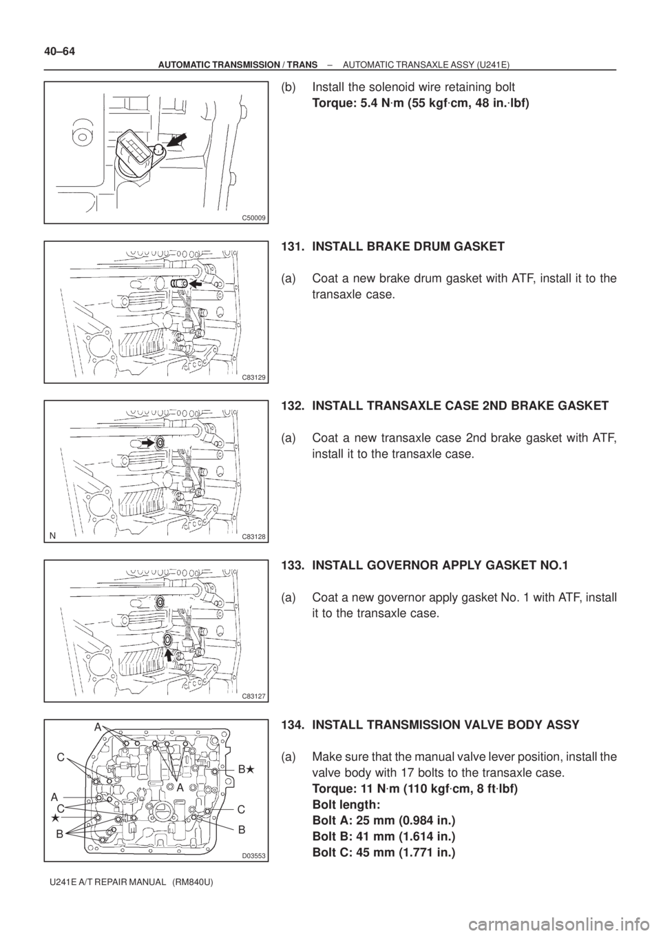
(b) Install the solenoid wire retaining bolt
Torque: 5.4 N�m (55 kgf�cm, 48 in.�lbf)
131. INSTALL BRAKE DRUM GASKET
(a) Coat a new brake drum gasket with ATF, install it to the
transaxle case.
132. INSTALL TRANSAXLE CASE 2ND BRAKE GASKET
(a) Coat a new transaxle case 2nd brake gasket with ATF,
install it to the transaxle case.
133. INSTALL GOVERNOR APPLY GASKET NO.1
(a) Coat a new governor apply gasket No. 1 with ATF, install
it to the transaxle case.
134. INSTALL TRANSMISSION VALVE BODY ASSY
(a) Make sure that the manual valve lever position, install the
valve body with 17 bolts to the transaxle case.
Torque: 11 N�m (110 kgf�cm, 8 ft�lbf)
Bolt length:
Bolt A: 25 mm (0.984 in.)
Bolt B: 41 mm (1.614 in.)
Bolt C: 45 mm (1.771 in.)
Page 3687 of 5135
D09178
D09180
D09179
± AUTOMATIC TRANSMISSION / TRANSAUTOMATIC TRANSAXLE ASSY (U241E)
40±65
U241E A/T REPAIR MANUAL (RM840U)
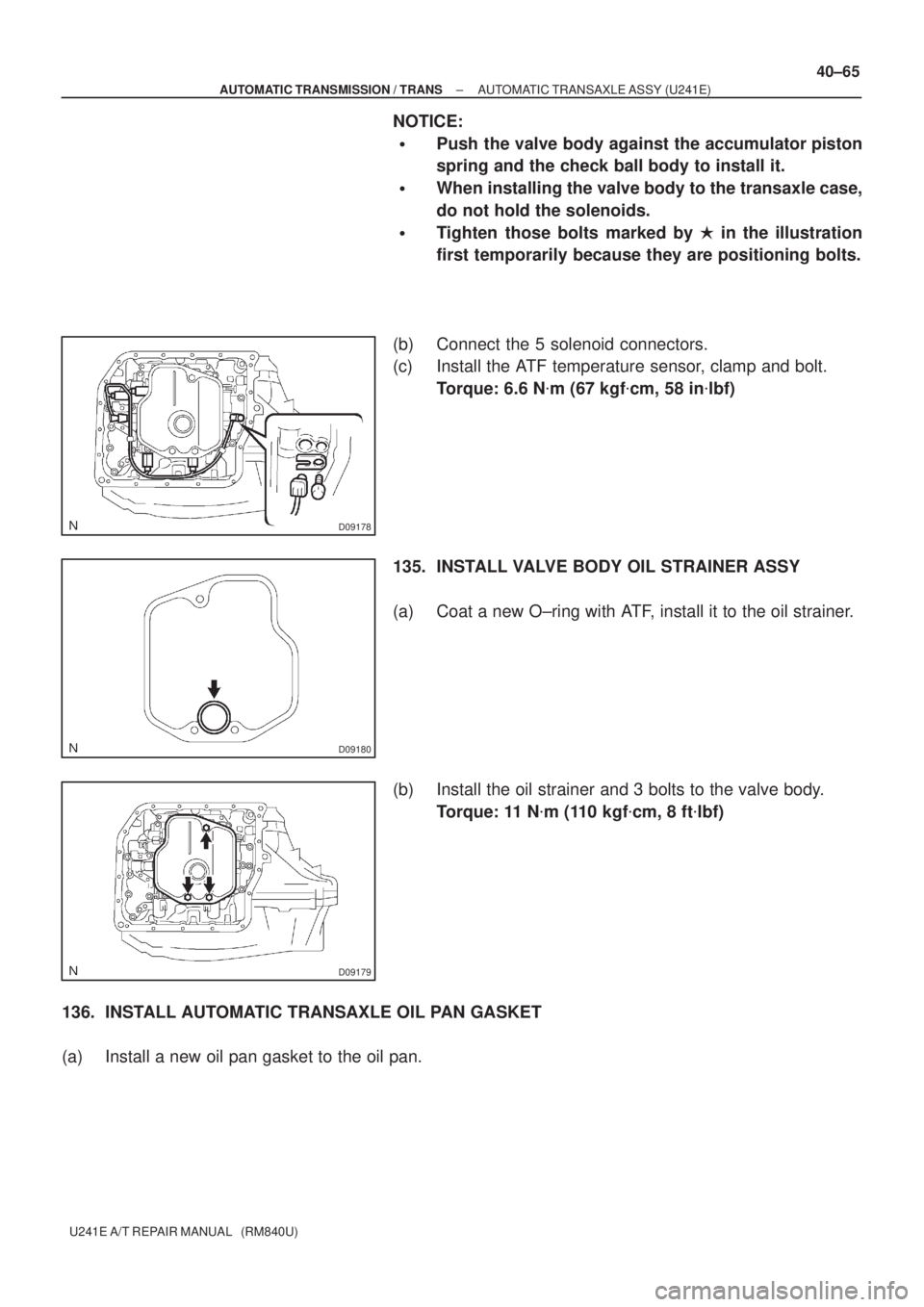
NOTICE:
�Push the valve body against the accumulator piston
spring and the check ball body to install it.
�When installing the valve body to the transaxle case,
do not hold the solenoids.
�Tighten those bolts marked by � in the illustration
first temporarily because they are positioning bolts.
(b) Connect the 5 solenoid connectors.
(c) Install the ATF temperature sensor, clamp and bolt.
Torque: 6.6 N�m (67 kgf�cm, 58 in�lbf)
135. INSTALL VALVE BODY OIL STRAINER ASSY
(a) Coat a new O±ring with ATF, install it to the oil strainer.
(b) Install the oil strainer and 3 bolts to the valve body.
Torque: 11 N�m (110 kgf�cm, 8 ft�lbf)
136. INSTALL AUTOMATIC TRANSAXLE OIL PAN GASKET
(a) Install a new oil pan gasket to the oil pan.
Page 3688 of 5135

U241E A/T REPAIR MANUAL (RM840U)
137. I N S TA L L A U TO M AT I C TRANSAXLE OIL PAN
SUB±")
D25674
D09176
D03900
D03900
C83144
40±66
± AUTOMATIC TRANSMISSION / TRANSAUTOMATIC TRANSAXLE ASSY (U241E)
U241E A/T REPAIR MANUAL (RM840U)
137. I N S TA L L A U TO M AT I C TRANSAXLE OIL PAN
SUB±ASSY
(a) Install the 2 magnets in the oil pan.
(b) Apply seal packing or equivalent to new 18 bolts.
Seal packing:
THREE BOND 2430 or equivalent
(c) Install oil pan and 18 bolts to the transaxle case.
Torque: 7.8 N�m (80 kgf�cm, 69 in.�lbf)
NOTICE:
Because the bolts should be seal bolts, apply seal packing
to new bolts and tighten them within 10 minutes after ap-
plication.
138. INSTALL SPEED SENSOR(TMC ±MADE)
(a) Coat 2 new O±rings with ATF, install them to the 2 sen-
sors.
(b) Install the 2 sensors with the 2 bolts to the transaxle case.
Torque: 11.3 N�m (115 kgf�cm, 8 ft�lbf)
139. I N S TA L L TRANSMISSION REVOLUTION
SENSOR(AISIN ±MADE)
(a) Coat 2 new O±rings with ATF, install them to the 2 sen-
sors.
(b) Install the 2 sensors with the 2 bolts to the transaxle case.
Torque: 11.3 N�m (115 kgf�cm, 8 ft�lbf)
140. INSTALL OIL COOLER TUBE UNION
(a) Coat a new O±ring with ATF, install it to the elbow.
(b) Install the elbow to the transaxle case.
Torque: 27 N�m (276 kgf�cm, 20 ft�lbf)
Page 3689 of 5135
C83143
C83142
D08034
D08093
± AUTOMATIC TRANSMISSION / TRANSAUTOMATIC TRANSAXLE ASSY (U241E)
40±67
U241E A/T REPAIR MANUAL (RM840U)
141. INSTALL OIL COOLER TUBE UNION
(a) Coat a new O±ring with ATF, install it to the union.
(b) Install the union to the transaxle case.
Torque: 27 N�m (280 kgf�cm, 20 ft�lbf)
142. INSTALL TRANSAXLE CASE NO.1 PLUG
(a) Coat 4 new O±rings with ATF, install them to the 4 trans-
axle case No. 1 plugs.
(b) Install the 4 transaxle case No. 1 plugs to the transaxle
case.
Torque: 7.4 N�m (75 kgf�cm, 65 in.�lbf)
143. INSTALL BREATHER PLUG HOSE
(a) Install the breather plug hose to the breather No. 2 plug.
144. INSTALL PARK/NEUTRAL POSITION SWITCH ASSY
(a) Install the park/neutral position switch onto the manual
valve lever shaft and temporarily install the 2 adjusting
bolts.
(b) Install a new nut stopper and nut.
Torque: 6.9 N�m (70 kgf�cm, 61 in.�lbf)
(c) Temporarily install control shaft lever.
Page 3690 of 5135
D08094
D09642
D08033
D08032
40±68
± AUTOMATIC TRANSMISSION / TRANSAUTOMATIC TRANSAXLE ASSY (U241E)
U241E A/T REPAIR MANUAL (RM840U)
(d) Turn the lever counterclockwise until it stops, and then
turn it clockwise 2 notches.
(e) Remove the control shaft lever.
(f) Align the groove with neutral basic line.
(g) Tighten the 2 bolts.
Torque: 5.4 N�m (55 kgf�cm, 48 in.�lbf)
(h) Using a screwdriver, stake the nut with the nut stopper.
(i) Install the control shaft lever, washer and nut.
Torque: 13 N�m (133 kgf�cm, 10 ft�lbf)
145. INSTALL SPEEDOMETER DRIVEN HOLE (ATM) COVER SUB±ASSY
(a) Coat the new O±ring with ATF and install it to the speedometer driven hole cover.
(b) Install the bolt and speedometer driven hole cover sub±assy to the transaxle assy.
Torque: 7.0 N�m (70 kgf�cm, 61 in.�lbf)

U241E A/T REPAIR MANUAL (RM840U)
Bolt length:
Bolt A: 27 mm (1.063 in.)
Bolt B: 16 mm (0.630 in.)")

40±63
U241E A/T REPAIR MANUAL (RM840U)
128. INSTALL C±3 ACCUMULATOR PISTON
(a) Coat a new O±ri")

40±67
U241E A/T REPAIR MANUAL (RM840U)
141. INSTALL OIL COOLER TUBE UNION
(a) Coat a new O±ring with A")

U241E A/T REPAIR MANUAL (RM840U)
(d) Turn the lever counterclockwise until it stops, and then
tur")