Page 3674 of 5135
D03794
D03609
D08071
D03610
SST
D09197
40±52
± AUTOMATIC TRANSMISSION / TRANSAUTOMATIC TRANSAXLE ASSY (U241E)
U241E A/T REPAIR MANUAL (RM840U)
(c) Coat 2 new O±rings with ATF, install them to the U/D
brake piston.
(d) Install the U/D brake piston to the transaxle case.
101. INSTALL UNDERDRIVE BRAKE RETURN SPRING
SUB±ASSY
(a) Install the U/D brake return spring to the U/D brake piston.
(b) Using SST, a snap ring expander and a press, install the
snap ring to the transaxle case.
SST 09387±00020
NOTICE:
Do not apply excessive pressure to it.
102. INSTALL UNDERDRIVE CLUTCH DISC NO.2
(a) Install the 3 discs and 3 plates to the transaxle case.
Page 3675 of 5135
D08050
D08082
D03907
D03925
Free
± AUTOMATIC TRANSMISSION / TRANSAUTOMATIC TRANSAXLE ASSY (U241E)
40±53
U241E A/T REPAIR MANUAL (RM840U)
(b) Using a screwdriver, install the snap ring.
(c) Using a dial indicator, measure the U/D brake piston
stroke while applying and releasing compressed air (392
kPa, 4.0 kgf/cm
2, 57 psi).
Piston stroke: 1.81 ± 2.20 mm (0.0713 ± 0.0866 in.)
HINT:
Select an appropriate flange from the table below so that it will
meet the specified value.
Flange thickness: mm (in.)
MarkThicknessMarkThickness
13.0 (0.118)33.4 (0.134)
23.2 (0.126)±±
(d) Temporally remove the snap ring and attach the flange.
Restore the snap ring.
103. INSTALL UNDERDRIVE 1 WAY CLUTCH ASSY
(a) Install the outer race retainer to the 1±way clutch.
(b) Install the U/D clutch assy to the 1±way clutch. Rotate the
U/D clutch assy to check the rotating direction for the lock
or free operation.
Page 3676 of 5135
C50158
D03581
D03580
D09691
D09692
40±54
± AUTOMATIC TRANSMISSION / TRANSAUTOMATIC TRANSAXLE ASSY (U241E)
U241E A/T REPAIR MANUAL (RM840U)
(c) Install the 1±way clutch to the transaxle case.
NOTICE:
Make sure that the mark on the 1±way clutch outer race is
visible.
(d) Using screwdriver, install the snap ring to the transaxle
case.
104. INSTALL UNDERDRIVE CLUTCH ASSY
(a) Coat the bearing and bearing race with petroleum jelly,
install them onto the U/D clutch.
Race diameter: mm (in.)
InsideOutside
Bearing37.73 (1.4854)58.0 (2.283)
Race29.9 (1.177)55.5 (2.185)
(b) Install the U/D clutch assy to the transaxle case.
105. INSTALL UNDERDRIVE PLANETARY GEAR ASSY
(a) Install the parking lock pawl pin and torsion spring to the
parking lock pawl.
(b) Temporarily install the parking lock pawl, shaft and spring
to the transaxle case as shown in the illustration.
Page 3677 of 5135

D03579
D09693
D03576
D03875
D
D25511
Dimension (1)
Dimension (2)
± AUTOMATIC TRANSMISSION / TRANSAUTOMATIC TRANSAXLE ASSY (U241E)
40±55
U241E A/T REPAIR MANUAL (RM840U)
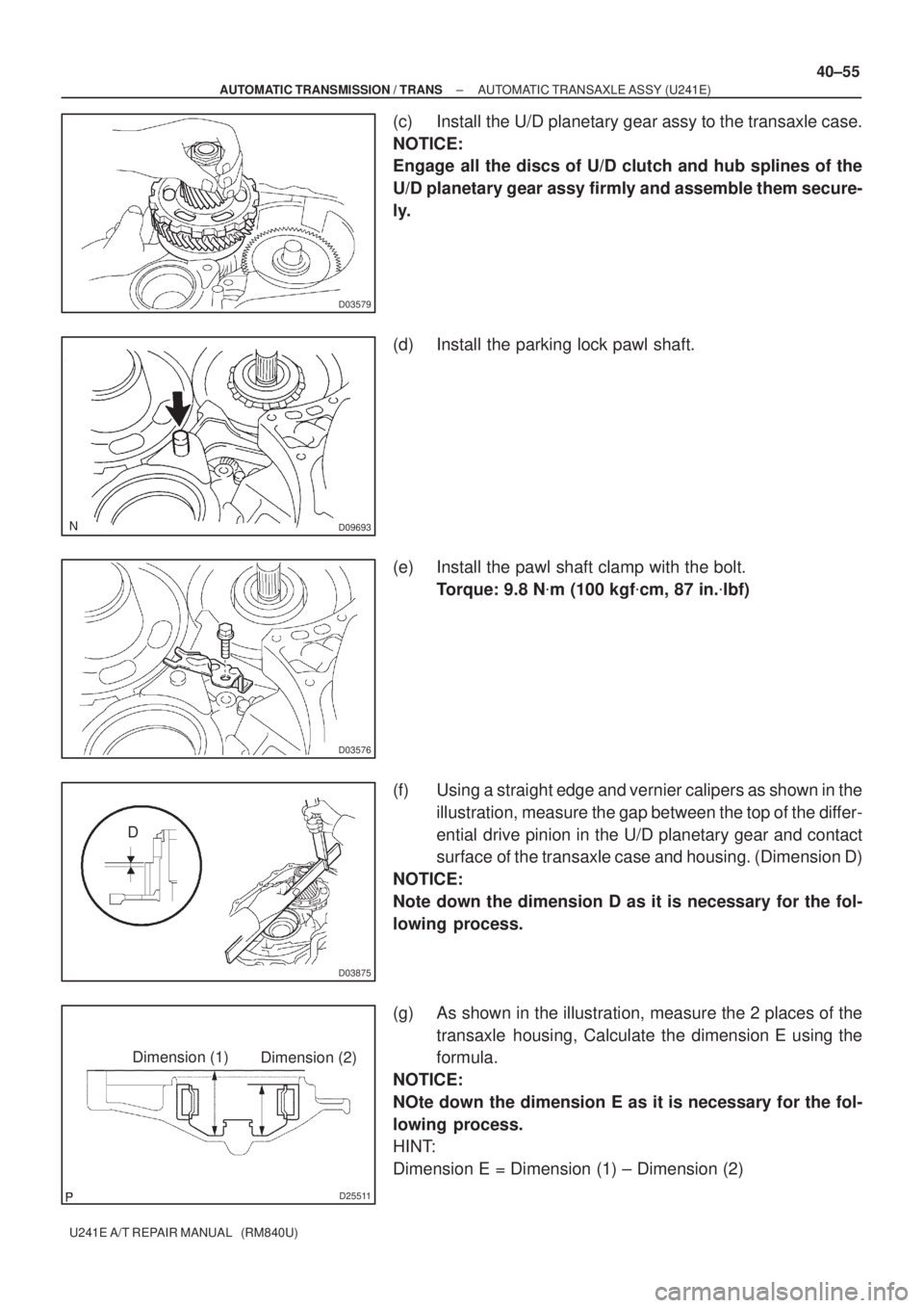
(c) Install the U/D planetary gear assy to the transaxle case.
NOTICE:
Engage all the discs of U/D clutch and hub splines of the
U/D planetary gear assy firmly and assemble them secure-
ly.
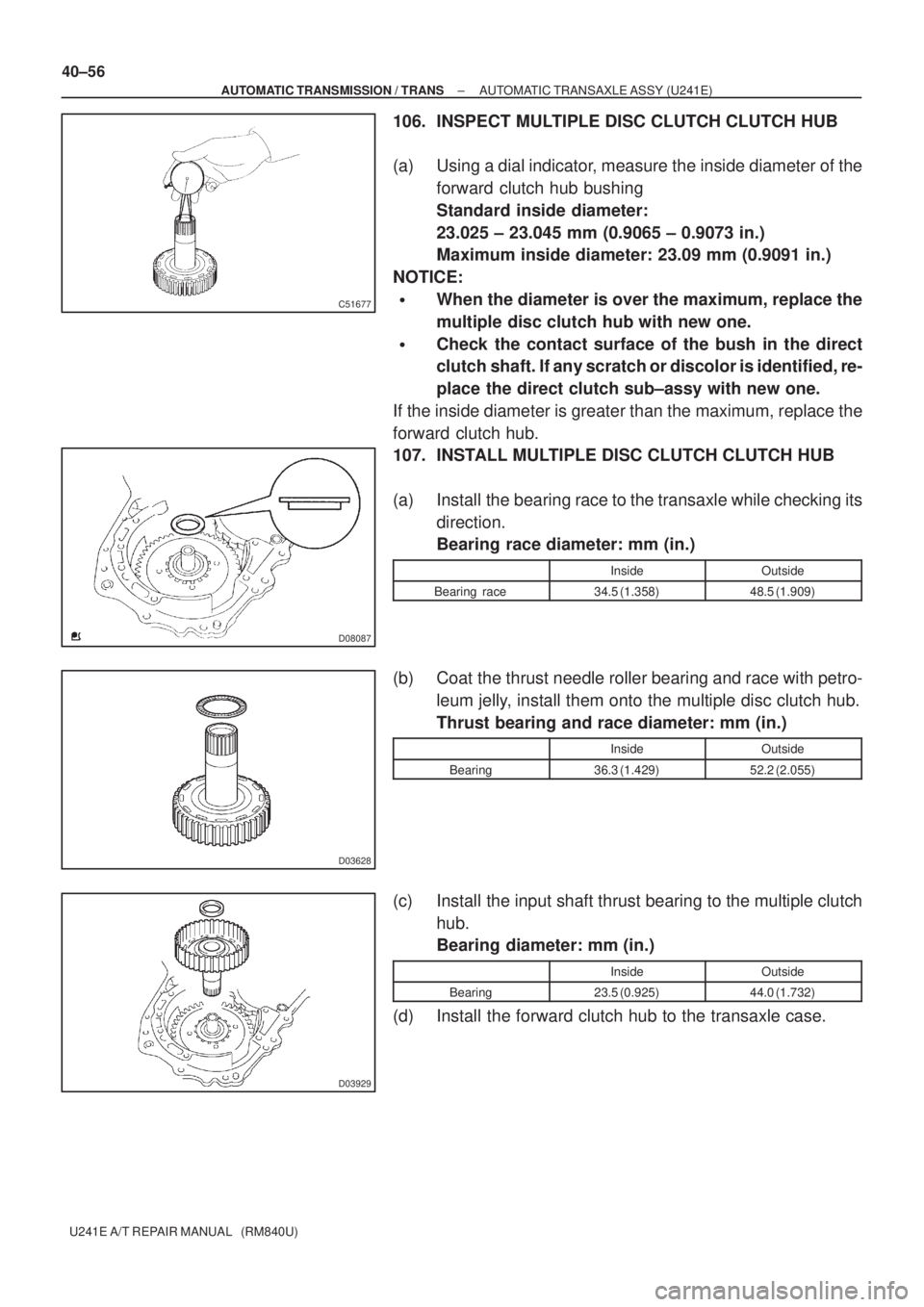
(d) Install the parking lock pawl shaft.
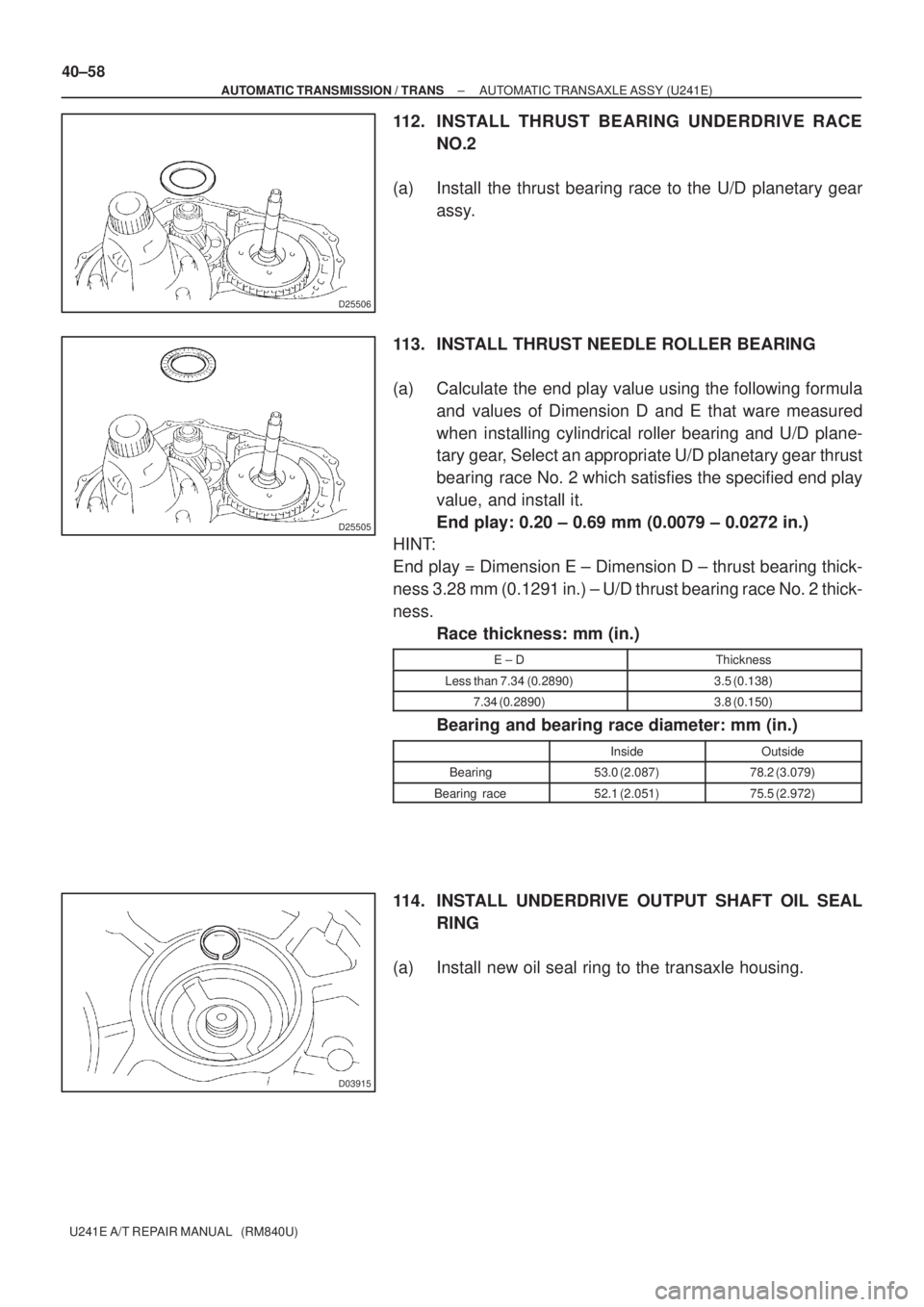
(e) Install the pawl shaft clamp with the bolt.
Torque: 9.8 N�m (100 kgf�cm, 87 in.�lbf)
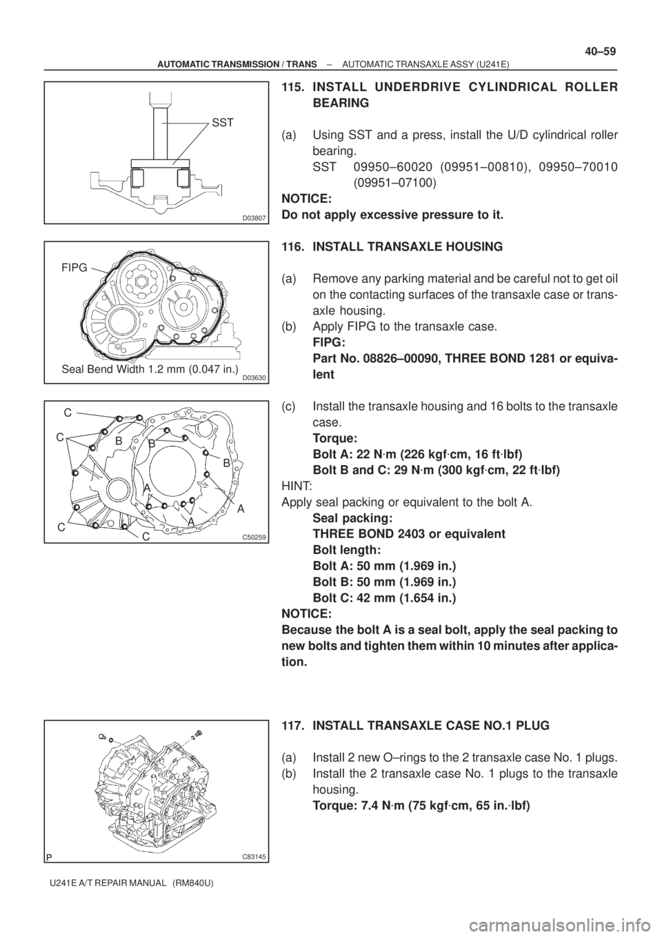
(f) Using a straight edge and vernier calipers as shown in the
illustration, measure the gap between the top of the differ-
ential drive pinion in the U/D planetary gear and contact
surface of the transaxle case and housing. (Dimension D)
NOTICE:
Note down the dimension D as it is necessary for the fol-
lowing process.
(g) As shown in the illustration, measure the 2 places of the
transaxle housing, Calculate the dimension E using the
formula.
NOTICE:
NOte down the dimension E as it is necessary for the fol-
lowing process.
HINT:
Dimension E = Dimension (1) ± Dimension (2)
Page 3678 of 5135

C51677
D08087
D03628
D03929
40±56
± AUTOMATIC TRANSMISSION / TRANSAUTOMATIC TRANSAXLE ASSY (U241E)
U241E A/T REPAIR MANUAL (RM840U)
106. INSPECT MULTIPLE DISC CLUTCH CLUTCH HUB
(a) Using a dial indicator, measure the inside diameter of the
forward clutch hub bushing
Standard inside diameter:
23.025 ± 23.045 mm (0.9065 ± 0.9073 in.)
Maximum inside diameter: 23.09 mm (0.9091 in.)
NOTICE:
�When the diameter is over the maximum, replace the
multiple disc clutch hub with new one.
�Check the contact surface of the bush in the direct
clutch shaft. If any scratch or discolor is identified, re-
place the direct clutch sub±assy with new one.
If the inside diameter is greater than the maximum, replace the
forward clutch hub.
107. INSTALL MULTIPLE DISC CLUTCH CLUTCH HUB
(a) Install the bearing race to the transaxle while checking its
direction.
Bearing race diameter: mm (in.)
InsideOutside
Bearing race34.5 (1.358)48.5 (1.909)
(b) Coat the thrust needle roller bearing and race with petro-
leum jelly, install them onto the multiple disc clutch hub.
Thrust bearing and race diameter: mm (in.)
InsideOutside
Bearing36.3 (1.429)52.2 (2.055)
(c) Install the input shaft thrust bearing to the multiple clutch
hub.
Bearing diameter: mm (in.)
InsideOutside
Bearing23.5 (0.925)44.0 (1.732)
(d) Install the forward clutch hub to the transaxle case.
Page 3680 of 5135

D25506
D25505
D03915
40±58
± AUTOMATIC TRANSMISSION / TRANSAUTOMATIC TRANSAXLE ASSY (U241E)
U241E A/T REPAIR MANUAL (RM840U)
112. INSTALL THRUST BEARING UNDERDRIVE RACE
NO.2
(a) Install the thrust bearing race to the U/D planetary gear
assy.
113. INSTALL THRUST NEEDLE ROLLER BEARING
(a) Calculate the end play value using the following formula
and values of Dimension D and E that ware measured
when installing cylindrical roller bearing and U/D plane-
tary gear, Select an appropriate U/D planetary gear thrust
bearing race No. 2 which satisfies the specified end play
value, and install it.
End play: 0.20 ± 0.69 mm (0.0079 ± 0.0272 in.)
HINT:
End play = Dimension E ± Dimension D ± thrust bearing thick-
ness 3.28 mm (0.1291 in.) ± U/D thrust bearing race No. 2 thick-
ness.
Race thickness: mm (in.)
E ± DThickness
Less than 7.34 (0.2890)3.5 (0.138)
7.34 (0.2890)3.8 (0.150)
Bearing and bearing race diameter: mm (in.)
InsideOutside
Bearing53.0 (2.087)78.2 (3.079)
Bearing race52.1 (2.051)75.5 (2.972)
114. INSTALL UNDERDRIVE OUTPUT SHAFT OIL SEAL
RING
(a) Install new oil seal ring to the transaxle housing.
Page 3681 of 5135

D03807
SST
D03630Seal Bend Width 1.2 mm (0.047 in.) FIPG
C50259
C
C
C
CA
AA B
BB
C83145
± AUTOMATIC TRANSMISSION / TRANSAUTOMATIC TRANSAXLE ASSY (U241E)
40±59
U241E A/T REPAIR MANUAL (RM840U)
115. INSTALL UNDERDRIVE CYLINDRICAL ROLLER
BEARING
(a) Using SST and a press, install the U/D cylindrical roller
bearing.
SST 09950±60020 (09951±00810), 09950±70010
(09951±07100)
NOTICE:
Do not apply excessive pressure to it.
116. INSTALL TRANSAXLE HOUSING
(a) Remove any parking material and be careful not to get oil
on the contacting surfaces of the transaxle case or trans-
axle housing.
(b) Apply FIPG to the transaxle case.
FIPG:
Part No. 08826±00090, THREE BOND 1281 or equiva-
lent
(c) Install the transaxle housing and 16 bolts to the transaxle
case.
Torque:
Bolt A: 22 N�m (226 kgf�cm, 16 ft�lbf)
Bolt B and C: 29 N�m (300 kgf�cm, 22 ft�lbf)
HINT:
Apply seal packing or equivalent to the bolt A.
Seal packing:
THREE BOND 2403 or equivalent
Bolt length:
Bolt A: 50 mm (1.969 in.)
Bolt B: 50 mm (1.969 in.)
Bolt C: 42 mm (1.654 in.)
NOTICE:
Because the bolt A is a seal bolt, apply the seal packing to
new bolts and tighten them within 10 minutes after applica-
tion.
117. INSTALL TRANSAXLE CASE NO.1 PLUG
(a) Install 2 new O±rings to the 2 transaxle case No. 1 plugs.
(b) Install the 2 transaxle case No. 1 plugs to the transaxle
housing.
Torque: 7.4 N�m (75 kgf�cm, 65 in.�lbf)
Page 3682 of 5135
D08091
D03631
D03632
D03905
D03565
40±60
± AUTOMATIC TRANSMISSION / TRANSAUTOMATIC TRANSAXLE ASSY (U241E)
U241E A/T REPAIR MANUAL (RM840U)
118. INSPECT INPUT SHAFT ENDPLAY
(a) Using a dial indicator, measure the input shaft end play.
End play: 0.26 ± 1.25 mm (0.0103 ± 0.0492 in.)
119. FIX AUTOMATIC TRANSAXLE ASSY
120. INSTALL MANUAL VALVE LEVER SHAFT OIL SEAL
(a) Coat a new oil seal with ATF, install it to the transaxle
case.
(b) Install the oil seal to the transaxle case.
121. INSTALL PARKING LOCK ROD SUB±ASSY
(a) Install the parking lock rod to the manual valve lever.
122. INSTALL MANUAL VALVE LEVER SUB±ASSY
(a) Install a new spacer and manual valve lever shaft to the
transaxle case.