Page 1509 of 5135
05±1458
± DIAGNOSTICSNAVIGATION SYSTEM
AVENSIS REPAIR MANUAL (RM1018E)
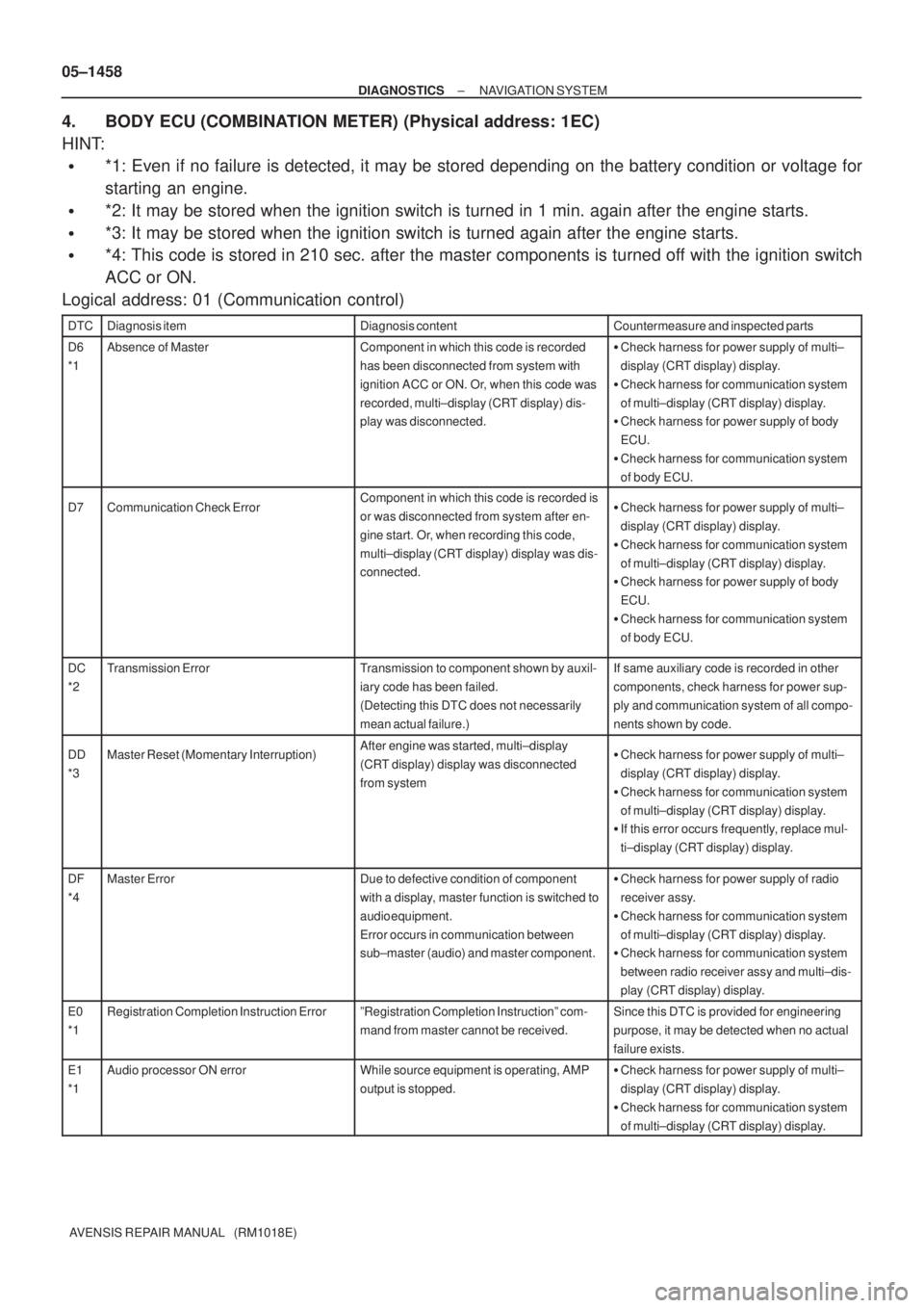
4. BODY ECU (COMBINATION METER) (Physical address: 1EC)
HINT:
�*1: Even if no failure is detected, it may be stored depending on the battery condition or voltage for
starting an engine.
�*2: It may be stored when the ignition switch is turned in 1 min. again after the engine starts.
�*3: It may be stored when the ignition switch is turned again after the engine starts.
�*4: This code is stored in 210 sec. after the master components is turned off with the ignition switch
ACC or ON.
Logical address: 01 (Communication control)
DTCDiagnosis itemDiagnosis contentCountermeasure and inspected parts
D6
*1Absence of MasterComponent in which this code is recorded
has been disconnected from system with
ignition ACC or ON. Or, when this code was
recorded, multi±display (CRT display) dis-
play was disconnected.�Check harness for power supply of multi±
display (CRT display) display.
�Check harness for communication system
of multi±display (CRT display) display.
�Check harness for power supply of body
ECU.
�Check harness for communication system
of body ECU.
D7Communication Check ErrorComponent in which this code is recorded is
or was disconnected from system after en-
gine start. Or, when recording this code,
multi±display (CRT display) display was dis-
connected.�Check harness for power supply of multi±
display (CRT display) display.
�Check harness for communication system
of multi±display (CRT display) display.
�Check harness for power supply of body
ECU.
�Check harness for communication system
of body ECU.
DC
*2Transmission ErrorTransmission to component shown by auxil-
iary code has been failed.
(Detecting this DTC does not necessarily
mean actual failure.)If same auxiliary code is recorded in other
components, check harness for power sup-
ply and communication system of all compo-
nents shown by code.
DD
*3Master Reset (Momentary Interruption)After engine was started, multi±display
(CRT display) display was disconnected
from system�Check harness for power supply of multi±
display (CRT display) display.
�Check harness for communication system
of multi±display (CRT display) display.
�If this error occurs frequently, replace mul-
ti±display (CRT display) display.
DF
*4Master ErrorDue to defective condition of component
with a display, master function is switched to
audio equipment.
Error occurs in communication between
sub±master (audio) and master component.�Check harness for power supply of radio
receiver assy.
�Check harness for communication system
of multi±display (CRT display) display.
�Check harness for communication system
between radio receiver assy and multi±dis-
play (CRT display) display.
E0
*1Registration Completion Instruction ErrorºRegistration Completion Instructionº com-
mand from master cannot be received.Since this DTC is provided for engineering
purpose, it may be detected when no actual
failure exists.
E1
*1Audio processor ON errorWhile source equipment is operating, AMP
output is stopped.�Check harness for power supply of multi±
display (CRT display) display.
�Check harness for communication system
of multi±display (CRT display) display.
Page 1510 of 5135
± DIAGNOSTICSNAVIGATION SYSTEM
05±1459
AVENSIS REPAIR MANUAL (RM1018E) DTCCountermeasure and inspected parts Diagnosis content Diagnosis item
E2ON/OFF Instruction Parameter ErrorError occurs in ON/OFF controlling com-
mand from stereo component amplifier assy.Replace radio receiver assy.
E3
*1Registration Request Transmission�Registration Request command is output
from slave component.
�Registration Connection Check Instruction,
Registration Request command is output
from sub±master component.Since this DTC is provided for engineering
purpose, it may be detected when no actual
failure exists.
Page 1511 of 5135
05C3D±01
I34712Multi±display (CRT display) Display Body ECU Radio Receiver Assy Navigation ECU
: AVC±LAN
05±1438
± DIAGNOSTICSNAVIGATION SYSTEM
AVENSIS REPAIR MANUAL (RM1018E)
PRE±CHECK
1. USER TROUBLES UNDER NORMAL CONDITION OF THE NAVIGATION SYSTEM
(a) Voice guidance does not perform in the following situation even if the system is in normal condition.
(1) The destination is not set up.
(2) The vehicle is not driving on the set route. (The remaining distance is not displayed at the lower
left of the map screen that tells the current position of the vehicle.)
(3) ºGuidance in Other Modesº is not set up. (In this case no voice guidance is given except on the
map screen.)
(b) The vehicle icon or map turns around arbitrarily on the screen even when the system is in normal condi-
tion.
If the ignition switch is turned to ºACCº or ºONº while the vehicle is turning around such as being on a turnta-
ble, the Navigation System memorizes the angle speed of that moment as the standard figure. To solve this
problem, at the vehicle speed of 0 MPH (0 km/h), turn off the ignition switch, and then turn it to ºACCº or ºONº
again to see whether any trouble occurs again.
2. INSPECTION OF THE LOCATION WITH TROUBLE OCCURRENCE
(a) Check whether the wrong display of the vehicle icon appears in a certain location or in several loca-
tions.
HINT:
It is difficult to determine the accurate vehicle position when driving on a freeway, a looped road or a road
which runs in parallel with another, and immediately after going out of the parking area. In such cases the
vehicle icon can be displayed off the real position of the vehicle.
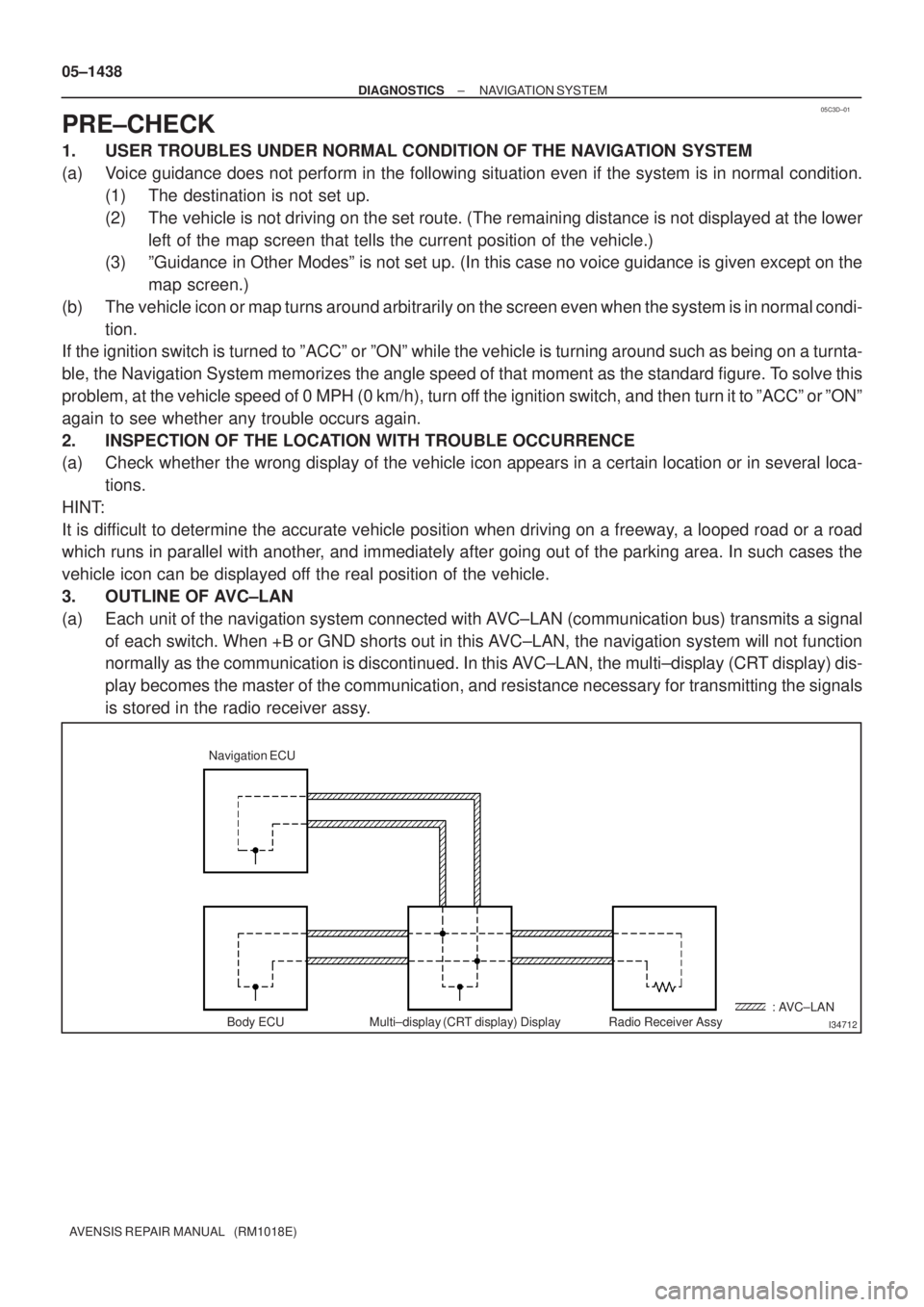
3. OUTLINE OF AVC±LAN
(a) Each unit of the navigation system connected with AVC±LAN (communication bus) transmits a signal
of each switch. When +B or GND shorts out in this AVC±LAN, the navigation system will not function
normally as the communication is discontinued. In this AVC±LAN, the multi±display (CRT display) dis-
play becomes the master of the communication, and resistance necessary for transmitting the signals
is stored in the radio receiver assy.
Page 1512 of 5135
I34691
Navigation system normal operation
Enter ºSERVICE CHECK MODEº (See section 5)
Enter ºNAVIGATION
CHECKº (See section 7)Diagnosis start±up (refer to next page)
HINT:
When Diagnosis System
mode starts, system
check is performed
at first and the check
result is displayed.
Enter ºDISPLAY CHECKº
(See section 6)
± DIAGNOSTICSNAVIGATION SYSTEM
05±1439
AVENSIS REPAIR MANUAL (RM1018E)
4. DIAGNOSIS SYSTEM MODE
Page 1513 of 5135
I34690
ºINFOº
Switch
Navigation Controller Assy:
I35902
05±1440
± DIAGNOSTICSNAVIGATION SYSTEM
AVENSIS REPAIR MANUAL (RM1018E)
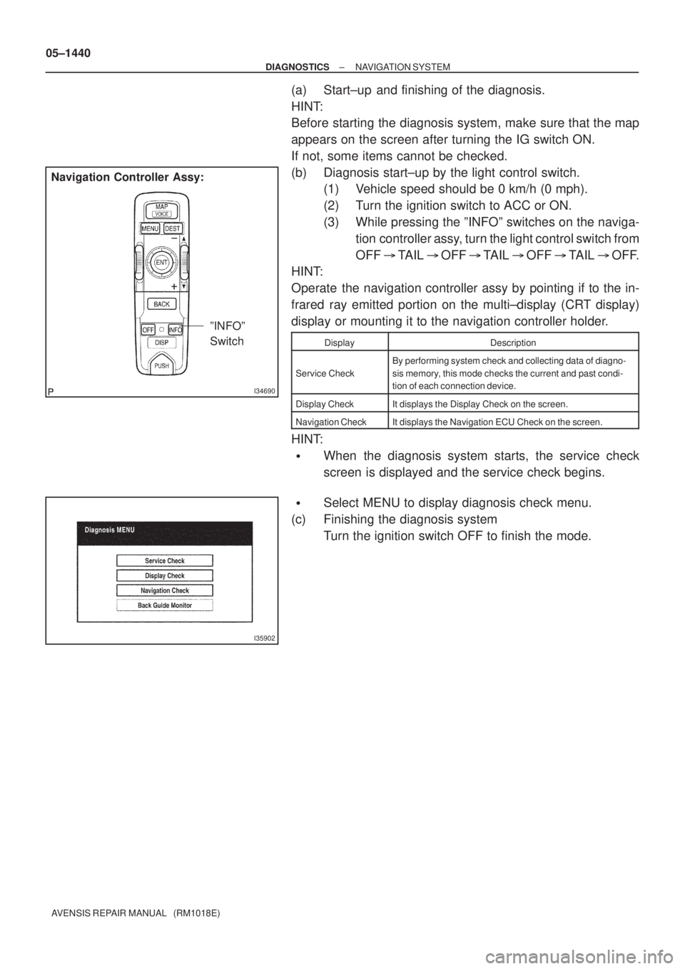
(a) Start±up and finishing of the diagnosis.
HINT:
Before starting the diagnosis system, make sure that the map
appears on the screen after turning the IG switch ON.
If not, some items cannot be checked.
(b) Diagnosis start±up by the light control switch.
(1) Vehicle speed should be 0 km/h (0 mph).
(2) Turn the ignition switch to ACC or ON.
(3) While pressing the ºINFOº switches on the naviga-
tion controller assy, turn the light control switch from
OFF � TAIL � OFF � TAIL � OFF � TAIL � OFF.
HINT:
Operate the navigation controller assy by pointing if to the in-
frared ray emitted portion on the multi±display (CRT display)
display or mounting it to the navigation controller holder.
DisplayDescription
Service Check
By performing system check and collecting data of diagno-
sis memory, this mode checks the current and past condi-
tion of each connection device.
Display CheckIt displays the Display Check on the screen.
Navigation CheckIt displays the Navigation ECU Check on the screen.
HINT:
�When the diagnosis system starts, the service check
screen is displayed and the service check begins.
�Select MENU to display diagnosis check menu.
(c) Finishing the diagnosis system
Turn the ignition switch OFF to finish the mode.
Page 1514 of 5135
I34692
to section 4. DIAGNOSIS
SYSTEM MODE
Recheck
DTC memory clear
DTC history clearDTC history clear
± DIAGNOSTICSNAVIGATION SYSTEM
05±1441
AVENSIS REPAIR MANUAL (RM1018E)
5. SERVICE CHECK MODE
Page 1515 of 5135
I34699
*2
*4*3
*5 *6
*7
*1*1
05±1442
± DIAGNOSTICSNAVIGATION SYSTEM
AVENSIS REPAIR MANUAL (RM1018E)
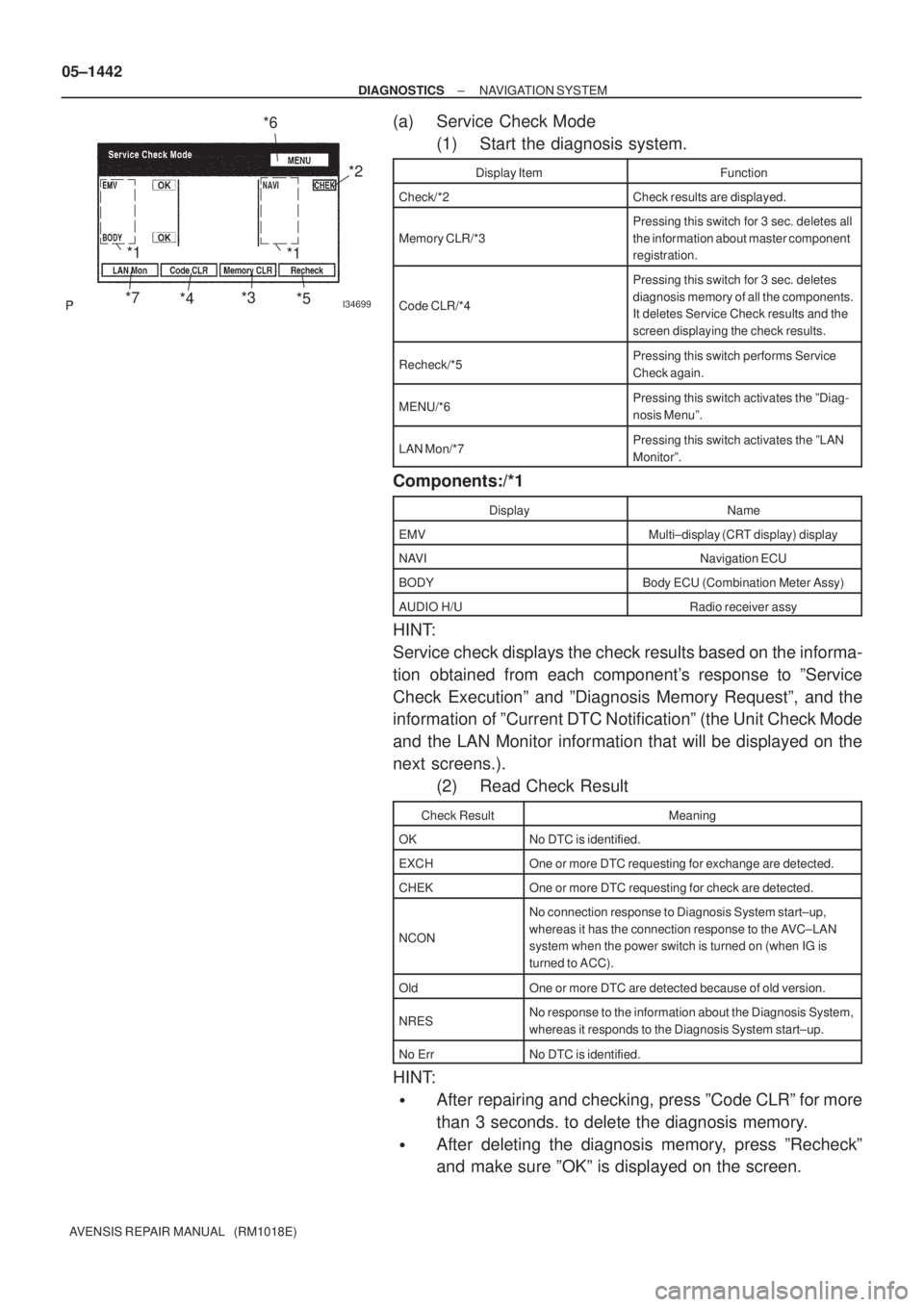
(a) Service Check Mode
(1) Start the diagnosis system.
Display ItemFunction
Check/*2Check results are displayed.
Memory CLR/*3
Pressing this switch for 3 sec. deletes all
the information about master component
registration.
Code CLR/*4
Pressing this switch for 3 sec. deletes
diagnosis memory of all the components.
It deletes Service Check results and the
screen displaying the check results.
Recheck/*5Pressing this switch performs Service
Check again.
MENU/*6Pressing this switch activates the ºDiag-
nosis Menuº.
LAN Mon/*7Pressing this switch activates the ºLAN
Monitorº.
Components:/*1
DisplayName
EMVMulti±display (CRT display) display
NAVINavigation ECU
BODYBody ECU (Combination Meter Assy)
AUDIO H/URadio receiver assy
HINT:
Service check displays the check results based on the informa-
tion obtained from each component's response to ºService
Check Executionº and ºDiagnosis Memory Requestº, and the
information of ºCurrent DTC Notificationº (the Unit Check Mode
and the LAN Monitor information that will be displayed on the
next screens.).
(2) Read Check Result
Check ResultMeaning
OKNo DTC is identified.
EXCHOne or more DTC requesting for exchange are detected.
CHEKOne or more DTC requesting for check are detected.
NCON
No connection response to Diagnosis System start±up,
whereas it has the connection response to the AVC±LAN
system when the power switch is turned on (when IG is
turned to ACC).
OldOne or more DTC are detected because of old version.
NRESNo response to the information about the Diagnosis System,
whereas it responds to the Diagnosis System start±up.
No ErrNo DTC is identified.
HINT:
�After repairing and checking, press ºCode CLRº for more
than 3 seconds. to delete the diagnosis memory.
�After deleting the diagnosis memory, press ºRecheckº
and make sure ºOKº is displayed on the screen.
Page 1516 of 5135
I32709
*3
*2
*4
*5*6
*1
I34700
*2
*1
*3
± DIAGNOSTICSNAVIGATION SYSTEM
05±1443
AVENSIS REPAIR MANUAL (RM1018E)
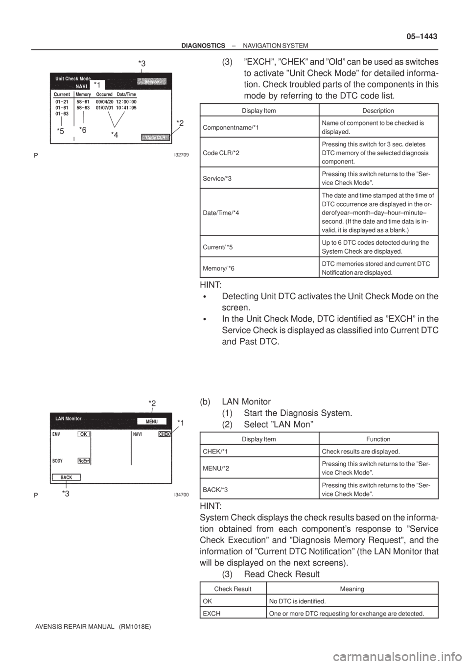
(3) ºEXCHº, ºCHEKº and ºOldº can be used as switches
to activate ºUnit Check Modeº for detailed informa-
tion. Check troubled parts of the components in this
mode by referring to the DTC code list.
Display ItemDescription
Component name/*1Name of component to be checked is
displayed.
Code CLR/*2
Pressing this switch for 3 sec. deletes
DTC memory of the selected diagnosis
component.
Service/*3Pressing this switch returns to the ºSer-
vice Check Modeº.
Date/Time/*4
The date and time stamped at the time of
DTC occurrence are displayed in the or-
der of year±month±day±hour±minute±
second. (If the date and time data is in-
valid, it is displayed as a blank.)
Current/ *5Up to 6 DTC codes detected during the
System Check are displayed.
Memory/ *6DTC memories stored and current DTC
Notification are displayed.
HINT:
�Detecting Unit DTC activates the Unit Check Mode on the
screen.
�In the Unit Check Mode, DTC identified as ºEXCHº in the
Service Check is displayed as classified into Current DTC
and Past DTC.
(b) LAN Monitor
(1) Start the Diagnosis System.
(2) Select ºLAN Monº
Display ItemFunction
CHEK/*1Check results are displayed.
MENU/*2Pressing this switch returns to the ºSer-
vice Check Modeº.
BACK/*3Pressing this switch returns to the ºSer-
vice Check Modeº.
HINT:
System Check displays the check results based on the informa-
tion obtained from each component's response to ºService
Check Executionº and ºDiagnosis Memory Requestº, and the
information of ºCurrent DTC Notificationº (the LAN Monitor that
will be displayed on the next screens).
(3) Read Check Result
Check ResultMeaning
OKNo DTC is identified.
EXCHOne or more DTC requesting for exchange are detected.