Page 1554 of 5135

I35667
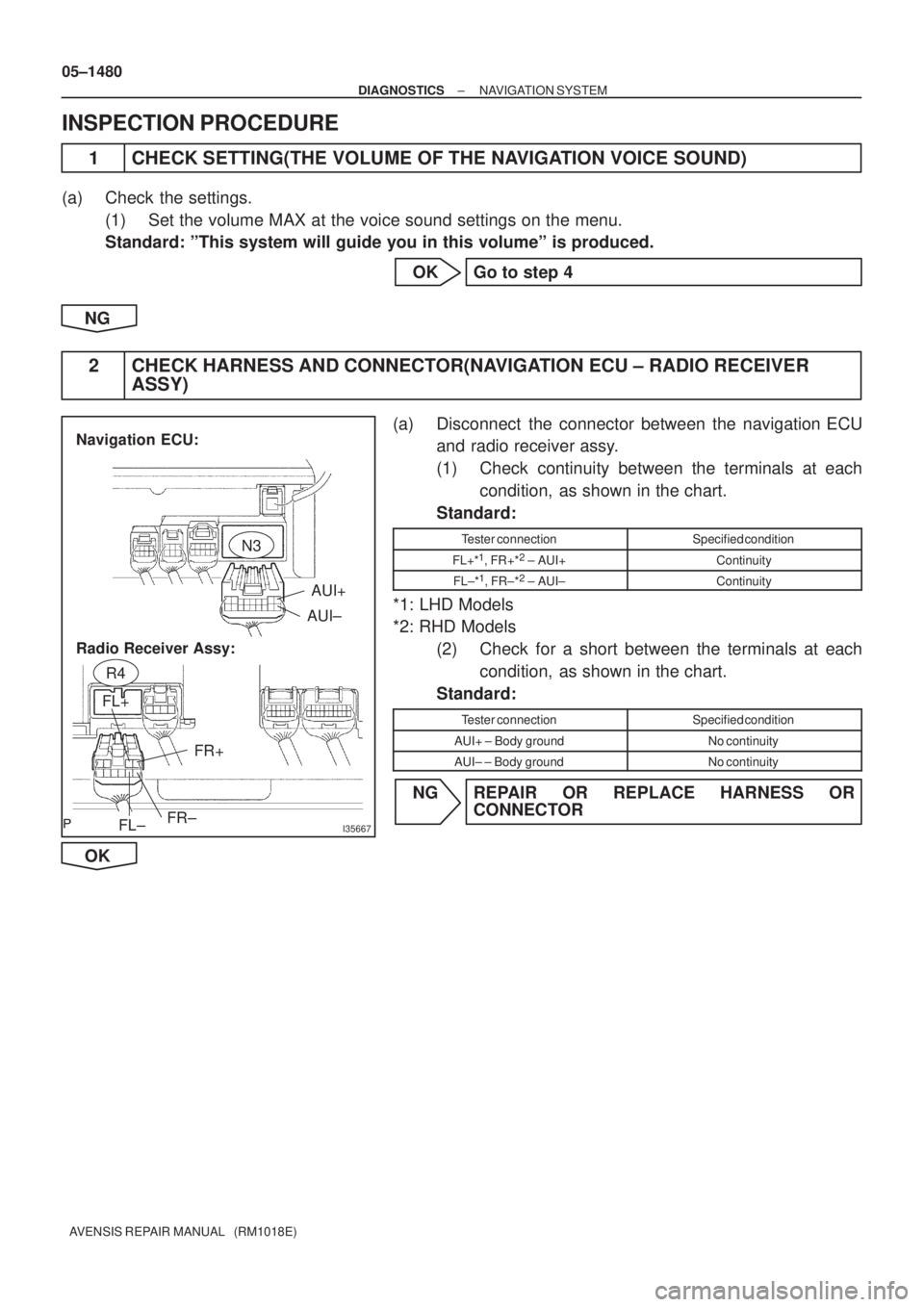
AUI+
AUI±
FL± FL+
FR±FR+
Navigation ECU:
Radio Receiver Assy:
N3
R4
05±1480
± DIAGNOSTICSNAVIGATION SYSTEM
AVENSIS REPAIR MANUAL (RM1018E)
INSPECTION PROCEDURE
1 CHECK SETTING(THE VOLUME OF THE NAVIGATION VOICE SOUND)
(a) Check the settings.
(1) Set the volume MAX at the voice sound settings on the menu.
Standard: ºThis system will guide you in this volumeº is produced.
OK Go to step 4
NG
2 CHECK HARNESS AND CONNECTOR(NAVIGATION ECU ± RADIO RECEIVER
ASSY)
(a) Disconnect the connector between the navigation ECU
and radio receiver assy.
(1) Check continuity between the terminals at each
condition, as shown in the chart.
Standard:
Tester connectionSpecified condition
FL+*1, FR+*2 ± AUI+Continuity
FL±*1, FR±*2 ± AUI±Continuity
*1: LHD Models
*2: RHD Models
(2) Check for a short between the terminals at each
condition, as shown in the chart.
Standard:
Tester connectionSpecified condition
AUI+ ± Body groundNo continuity
AUI± ± Body groundNo continuity
NG REPAIR OR REPLACE HARNESS OR
CONNECTOR
OK
Page 1555 of 5135
I35668
FL+FR+
FR±FL±
R4
±
DIAGNOSTICS NAVIGATION SYSTEM
05±1481
AVENSIS REPAIR MANUAL (RM1018E)
3INSPECT RADIO RECEIVER ASSY(FL+(*1), FL±(*1), FR+(*2), FR±(*2), \
GND)
(a)Remove the radio receiver assy.
(b)Using an oscilloscope, check the signal waveform be-
tween the terminals FL+*
1, FL±*1, FR+*2, FR±*2 and GND
of stereo component amplifier assy.
*1: LHD Models
*2: RHD Models
Standard:
Tester connectionConditionSpecified condition
FL+*1, FR+*2 ± GNDWhile voice sound is being producedA waveform synchronized with sound is output
FL±*1, FL±*2 ±GNDWhile voice sound is being producedA waveform synchronized with sound is output
NGREPLACE RADIO RECEIVER ASSY (See page 67±5)
OK
4 INSPECT FRONT NO.1 SPEAKER ASSY
(a) Resistance check (1) Check resistance between the terminals of the front No.1 speaker assy.
Standard: 4 �
NOTICE:
The speaker should not be removed for checking
NG REPLACE FRONT NO.1 SPEAKER ASSY (See page 67±10)
OK
Page 1556 of 5135
I33631
Navigation ECU:
Front No. 1 Speaker Assy LH:AUO+
AUO±
N3
Front No. 1 Speaker Assy RH:
F21
F22
05±1482
±
DIAGNOSTICS NAVIGATION SYSTEM
AVENSIS REPAIR MANUAL (RM1018E)
5CHECK HARNESS AND CONNECTOR(NAVIGATION ECU ± FRONT NO. 1 SPEAKER ASSY)
(a)Disconnect the connectors from the navigation ECU and
front No.1 speaker assy.
(1)Check continuity between the terminals at eachcondition, as shown in the chart.
Standard:
Tester connectionSpecified condition
AUO+ ± 1Continuity
AUO± ± 2Continuity
(2)Check for a short between the terminals at each condition, as shown in the chart.
Standard:
Tester connectionSpecified condition
AUO+ ± Body groundNo continuity
AUO± ± Body groundNo continuity
NGREPAIR OR REPLACE HARNESS OR CONNECTOR
OK
REPLACE NAVIGATION ECU (See page 67±27)
Page 3125 of 5135
I35174
I35177
I35176
I351782 Clips
I35179
± AUDIO & VISUAL SYSTEMMULTI±DISPLAY (CRT DISPLAY) DISPLAY
67±7
AVENSIS REPAIR MANUAL (RM1018E)
(b) Remove the 4 screws and the instrument cluster finish
panel assy.
6. REMOVE CONTROL KNOB PROTECTOR NO.1
(a) Remove the screw and control knob protector No.1.
(b) Separate the position sensor.
7. REMOVE MULTI±DISPLAY (CRT DISPLAY) DISPLAY
(a) Remove the 4 screws and separate the navigation com-
puter cover.
(b) Disengage the 2 clips, slide them in the arrow direction
shown in the illustration to remove the navigation comput-
er cover.
(c) Slide the lock of the connector in the arrow direction
shown in the illustration to disconnect the flexible flat
cable.
Page 3129 of 5135
670S5±01
I35223
Instrument Cluster Finish Panel Garnish No.2
Radio Bracket No.2Radio Receiver Assy
Instrument Panel
Register Assy CTR
Air Conditioning Control AssyConsole Panel
Sub±assy Upper
Navigation System:Navigation Computer Cover
Instrument Panel
Support No.3 Instrument Panel
Support No.1Instrument Panel
Support No.2
Door Control Motor
Door Control Switch
Assy (TILT)
Instrument Cluster Finish Panel AssyDoor Control Switch Instrument Cluster Finish
Upper PanelMulti±display Instrument Panel Box
Door CoverRadio Bracket No.1
Instrument Panel
Register Control Gear
Control Knob
Protector No.1
Position Sensor
67±2
± AUDIO & VISUAL SYSTEMAUDIO & VISUAL SYSTEM
AVENSIS REPAIR MANUAL (RM1018E)
COMPONENTS
Page 3130 of 5135
I35224
Front No.2 Speaker AssyAmplifier Antenna Assy
Front No.1 Speaker
Assy
Rear Speaker AssyNavigation System:
Disc Player Bracket No.2 Rivet
Navigation ECUPower Point Socket Cover
Power Point Socket Assy
Liftback:
Antenna Cord Sub±assy No.3Amplifier Antenna Assy Wagon:
Non±reusable part ��
Disc Player Bracket No.3
Rivet �
Rear No.2 Speaker Assy
Navigation ECU Cover
± AUDIO & VISUAL SYSTEMAUDIO & VISUAL SYSTEM
67±3
AVENSIS REPAIR MANUAL (RM1018E)
Page 3131 of 5135
I35225
Navigation System:
Navigation Antenna Assy
Cigarette lighter Socket &
Retainer Assy
Cigarette lighter Knob
& Element Assy 67±4
± AUDIO & VISUAL SYSTEMAUDIO & VISUAL SYSTEM
AVENSIS REPAIR MANUAL (RM1018E)
Page 3165 of 5135
670SI±02
I35212
67±28
±
AUDIO & VISUAL SYSTEM NAVIGATION ANTENNA ASSY
AVENSIS REPAIR MANUAL (RM1018E)
NAVIGATION ANTENNA ASSY
REPLACEMENT
1.DISCONNECT BATTERY NEGATIVE TERMINAL (See page 60±1)
2.REMOVE INSTRUMENT PANEL SUB±ASSY UPPER W/INSTR PNL PASS L/DOOR AIR BAG ASSY (See page 71±11)
3.REMOVE NAVIGATION ANTENNA ASSY
(a)Disconnect the connector.
(b)Remove the 2 screws and navigation antenna assy.
4.INSTALL INSTRUMENT PANEL SUB±ASSY UPPER W/INSTR PNL PASS L/DOOR AIR BAG ASSY (See page 71±11)