Page 1525 of 5135
I34710
*1
05±1452
± DIAGNOSTICSNAVIGATION SYSTEM
AVENSIS REPAIR MANUAL (RM1018E)
(f) Memory Copy/ Paste
HINT:
This function is not available.
Display ItemMeaning
Navi Menu/*1Pressing this switch returns to the ºNavi-
gation Checkº.
Page 1539 of 5135
I35657
S15
Steering Pad Switch LH
Multi±display
(CRT Display) DisplayAU1
AU2
EAU12
11
10LG (*1)
P (*1)
W±R (*1)
GTX+
GTX±
CTX±
CTX+M1
M1
M2
M25
18
10
5P
LG
LG
V
T11
Telephone Microphone Assy
MACC
MIC+
MIC±5
4
2R
B
W
(Shielded)17
ID1
ID1
ID1
ID118
16
14R
B
W
(Shielded)Radio Receiver Assy
7
8
6 R7
R7
R7SW1
SW2
GND
TX+
TX± R6
R69
10
Navigation ECU
TX±
TX+
MACC
MIC+
MIC±
SGND N4
N4
N5
N5
N5
N54
3
5
6 BR
BR
*1: w/ Steering SW10
5 05±1494
± DIAGNOSTICSNAVIGATION SYSTEM
AVENSIS REPAIR MANUAL (RM1018E)
THE SYSTEM CANNOT BE OPERATED BY THE VOICE SOUND
WIRING DIAGRAM
05C3W±01
Page 1540 of 5135
I35662
EAU
AU2 ºVOICEº switch
S15
±
DIAGNOSTICS NAVIGATION SYSTEM
05±1495
AVENSIS REPAIR MANUAL (RM1018E)
INSPECTION PROCEDURE
1INSPECT STEERING WHEEL ASSY(BEEP SOUND)
(a)Check the switch (Beep sound).
(1)Press steering pad switch LH to check that the beep sound is produced.
OKGo to step 3
NG
2INSPECT STEERING WHEEL ASSY(AU2, EAU)
(a)Remove the horn button assy(See page 50±9).
(b)Check continuity between the terminals at each condi- tion, as shown in the chart.
Tester connectionConditionSpecified condition
AU2 ± EAUDo not switch positionApprox. 100 k �
AU2 ± EAUVOICE switch: pushApprox. 3.1 k
NGREPLACE STEERING WHEEL ASSY
(See page 50±9)
OK
3 CHECK TALK BACK
(a) Check whether the system performs talk back or not. Standard: The system performs talk back.
OK SYSTEM OK
NG
Page 1541 of 5135
I35670
MIC+
MACC MIC±
MACC MIC+ MIC±
Navigation ECU:
Telephone Microphone Assy:
T11
N5
05±1496
±
DIAGNOSTICS NAVIGATION SYSTEM
AVENSIS REPAIR MANUAL (RM1018E)
4CHECK HARNESS AND CONNECTOR(NAVIGATION ECU ± TELEPHONE MICROPHONE ASSY)
(a)Disconnect the connectors from the navigation ECU and
telephone microphone assy.
(1)Check continuity between the terminals at eachcondition, as shown in the chart.
Standard:
Tester connectionSpecified condition
MACC ± MACCContinuity
MIC+ ± MIC+Continuity
MIC± ± MIC±Continuity
(2)Check for a short between the terminals at each condition, as shown in the chart.
Standard:
Tester connectionSpecified condition
MACC ± Body groundNo continuity
MIC+ ± Body groundNo continuity
MIC± ± Body groundNo continuity
NGREPAIR OR REPLACE HARNESS OR CONNECTOR
OK
5REPLACE TELEPHONE MICROPHONE ASSY
Standard: Normally returns NGREPLACE NAVIGATION ECU (See page 67±27)
OK
SYSTEM OK
Page 1542 of 5135
I34721
R11
Navigation Controller Holder
(Shielded)Multi±display
(CRT Display) Display
TX
SGND3
2R
(Shielded)10
22 M1
M1RE1
SGD1
I35661
05±1492
± DIAGNOSTICSNAVIGATION SYSTEM
AVENSIS REPAIR MANUAL (RM1018E)
WHEN MOUNT THE NAVIGATION CONTROLLER ASSY TO THE
NAVIGATION CONTROLLER HOLDER, IT CANNOT BE OPERATED
WIRING DIAGRAM
INSPECTION PROCEDURE
1 CLEAN THE INFRARED RAY EMITTED PORTION
(a) Clean the infrared ray emitted portion.
(1) Clean the infrared ray emitted portion on the navi-
gation controller holder and navigation controller
assy.
(2) Check whether the same malfunction occurs.
Standard: The function returns to normal.
OK DIRT AT THE INFRARED RAY EMITTED
PORTION
NG
05C3V±01
Page 1543 of 5135

I35698
Multi±display (CRT Display) Display:Navigation Controller Holder:
R11
M1
SGND
TX
RE1 SGD1
±
DIAGNOSTICS NAVIGATION SYSTEM
05±1493
AVENSIS REPAIR MANUAL (RM1018E)
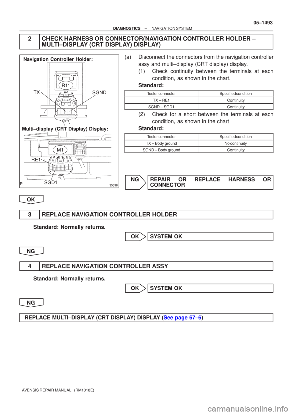
2CHECK HARNESS OR CONNECTOR(NAVIGATION CONTROLLER HOLDER ±
MULTI±DISPLAY (CRT DISPLAY) DISPLAY)
(a)Disconnect the connectors from the navigation controller
assy and multi±display (CRT display) display.
(1)Check continuity between the terminals at eachcondition, as shown in the chart.
Standard:
Tester connecterSpecified condition
TX ± RE1Continuity
SGND ± SGD1Continuity
(2)Check for a short between the terminals at each condition, as shown in the chart
Standard:
Tester connecterSpecified condition
TX ± Body groundNo continuity
SGND ± Body groundContinuity
NGREPAIR OR REPLACE HARNESS OR CONNECTOR
OK
3REPLACE NAVIGATION CONTROLLER HOLDER
Standard: Normally returns. OKSYSTEM OK
NG
4REPLACE NAVIGATION CONTROLLER ASSY
Standard: Normally returns. OKSYSTEM OK
NG
REPLACE MULTI±DISPLAY (CRT DISPLAY) DISPLAY (See page 67±6)
Page 1544 of 5135

I35660
±
DIAGNOSTICS NAVIGATION SYSTEM
05±1491
AVENSIS REPAIR MANUAL (RM1018E)
A NAVIGATION CONTROLLER ASSY DOES NOT OPERATE
INSPECTION PROCEDURE
1CHECK MALFUNCTION SYMPTOMS
(a)Check obstruction.
(1)Check that there are no obstructions between the navigation controller assy a\
nd the infrared ray
light emission portion of the multi±display (CRT display) display.
Standard: Normally returns
OKSYSTEM OK
NG
2CHECK BATTERY(NAVIGATION CONTROLLER ASSY)
(a)Check battery. (1)Check that the dry±cell battery used for the navigation controller as\
sy is not dead.
Standard: It is not dead
NGBATTERY IS DEAD
OK
3CLEAN THE INFRARED RAY EMITTED PORTION
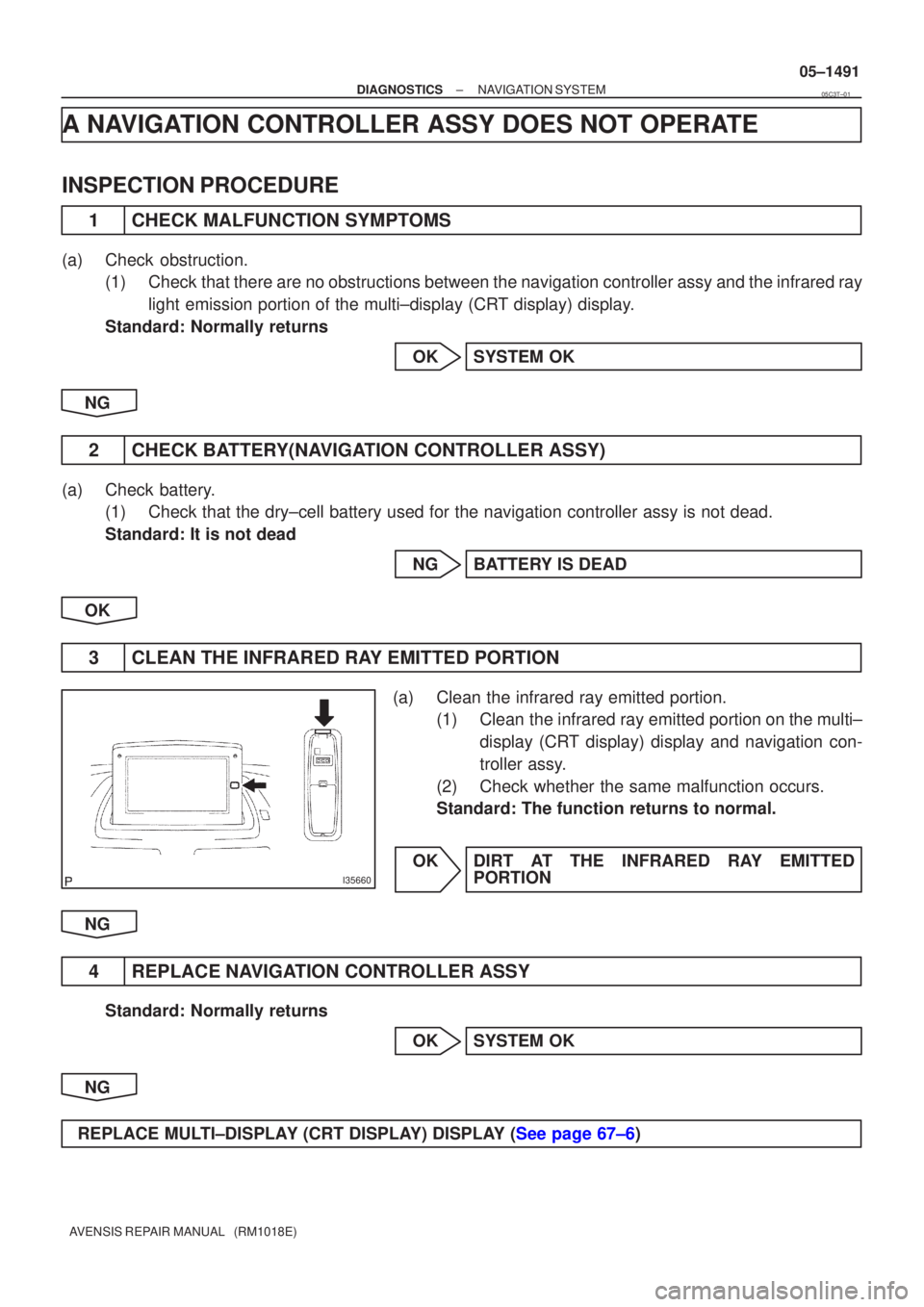
(a)Clean the infrared ray emitted portion. (1)Clean the infrared ray emitted portion on the multi±
display (CRT display) display and navigation con-
troller assy.
(2)Check whether the same malfunction occurs.
Standard: The function returns to normal.
OKDIRT AT THE INFRARED RAY EMITTED PORTION
NG
4REPLACE NAVIGATION CONTROLLER ASSY
Standard: Normally returns OKSYSTEM OK
NG
REPLACE MULTI±DISPLAY (CRT DISPLAY) DISPLAY (See page 67±6)
05C3T±01
Page 1545 of 5135

I34724
Neutral Start SW (*4)
Back±up Light SW (*5)21
N1B1
(*4)(*5) 5
IK1
R±YR±Y (*3)R±Y (*1)
R±Y (*2)R±Y (*2)AA
CC
J5
J/C
J22
J/C 14
N3
Navigation ECU
REV
*1: LHD
*2: RHD
*3: LHD Except 1ZZ±FE, 3ZZ±FE *4: A/T
*5: M/T
I32703REV
N3
05±1490
±
DIAGNOSTICS NAVIGATION SYSTEM
AVENSIS REPAIR MANUAL (RM1018E)
DRIVING DIRECTIONS ARE OPPOSITE TO MOVING DIRECTION OF VEHICLE POSITION MARK
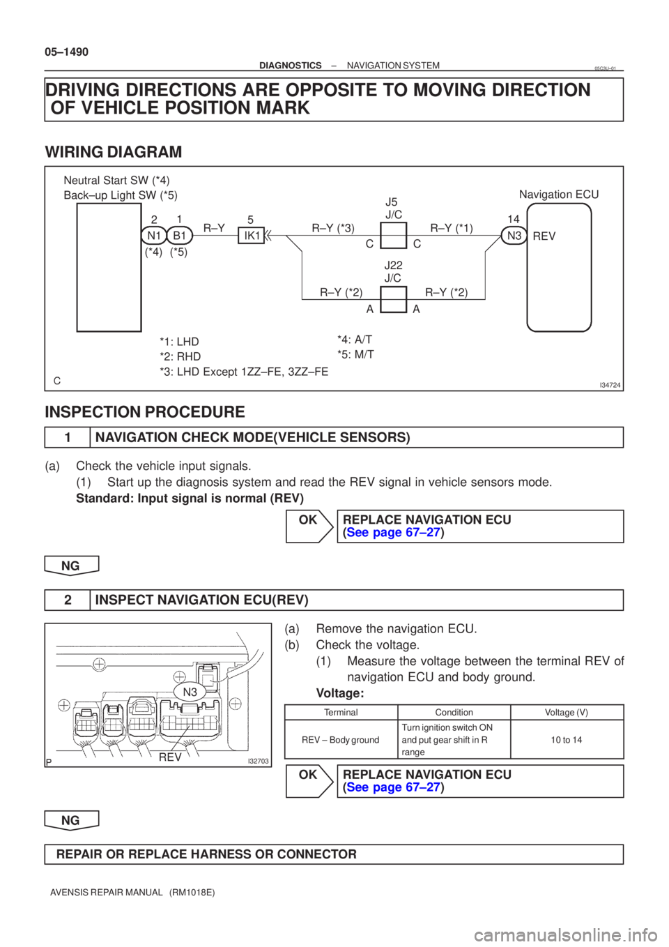
WIRING DIAGRAM
INSPECTION PROCEDURE
1NAVIGATION CHECK MODE(VEHICLE SENSORS)
(a)Check the vehicle input signals.
(1)Start up the diagnosis system and read the REV signal in vehicle sensors\
mode.
Standard: Input signal is normal (REV)
OKREPLACE NAVIGATION ECU (See page 67±27)
NG
2INSPECT NAVIGATION ECU(REV)
(a)Remove the navigation ECU.
(b)Check the voltage. (1)Measure the voltage between the terminal REV ofnavigation ECU and body ground.
Voltage:
TerminalConditionVoltage (V)
REV ±Body ground
Turn ignition switch ON
and put gear shift in R
range
10 to 14
OKREPLACE NAVIGATION ECU (See page 67±27)
NG
REPAIR OR REPLACE HARNESS OR CONNECTOR
05C3U±01