Page 1517 of 5135
I34701
*6
*5
*4 *3
*2
*1*7
05±1444
± DIAGNOSTICSNAVIGATION SYSTEM
AVENSIS REPAIR MANUAL (RM1018E)CHEK
One or more DTC requesting for check are detected.
NCON
No connection response to Diagnosis System start±up,
where as it has the connection response to the AVC±LAN
system when the power switch is turned on (when IG is
turned to ACC).
OldOne or more DTC are detected because of old version.
NRESNo response to the information about the Diagnosis System,
where as it responds to the Diagnosis System start±up.
No ErrNo DTC is identified.
HINT:
�After repair and check, press ºCode CLRº for more than
3 sec. to delete the diagnosis memory.
�After deleting the diagnosis memory, press ºRecheckº
and make sure ºOKº is displayed on the screen.
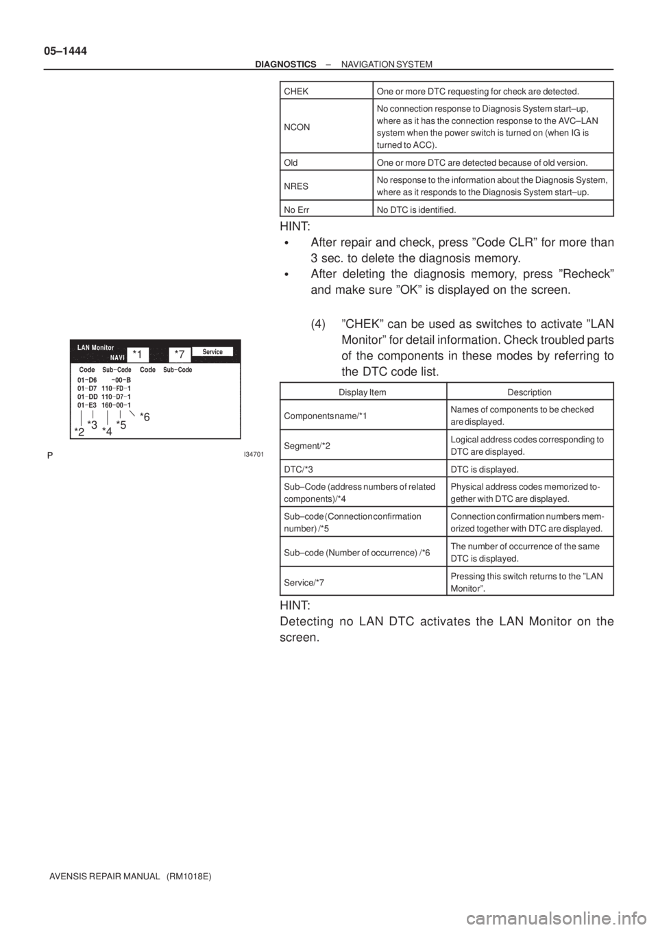
(4) ºCHEKº can be used as switches to activate ºLAN
Monitorº for detail information. Check troubled parts
of the components in these modes by referring to
the DTC code list.
Display ItemDescription
Components name/*1Names of components to be checked
are displayed.
Segment/*2Logical address codes corresponding to
DTC are displayed.
DTC/*3DTC is displayed.
Sub±Code (address numbers of related
components)/*4Physical address codes memorized to-
gether with DTC are displayed.
Sub±code (Connection confirmation
number) /*5Connection confirmation numbers mem-
orized together with DTC are displayed.
Sub±code (Number of occurrence) /*6The number of occurrence of the same
DTC is displayed.
Service/*7Pressing this switch returns to the ºLAN
Monitorº.
HINT:
Detecting no LAN DTC activates the LAN Monitor on the
screen.
Page 1518 of 5135
I34693
to section 4.
DIAGNOSIS
SYSTEM MODE
Select a
color barEnter switch
± DIAGNOSTICSNAVIGATION SYSTEM
05±1445
AVENSIS REPAIR MANUAL (RM1018E)
6. DISPLAY CHECK MODE
Page 1519 of 5135
I34702
*2 *4
*3 *1
I34711
Select a
color barEnter switch*1
05±1446
± DIAGNOSTICSNAVIGATION SYSTEM
AVENSIS REPAIR MANUAL (RM1018E)
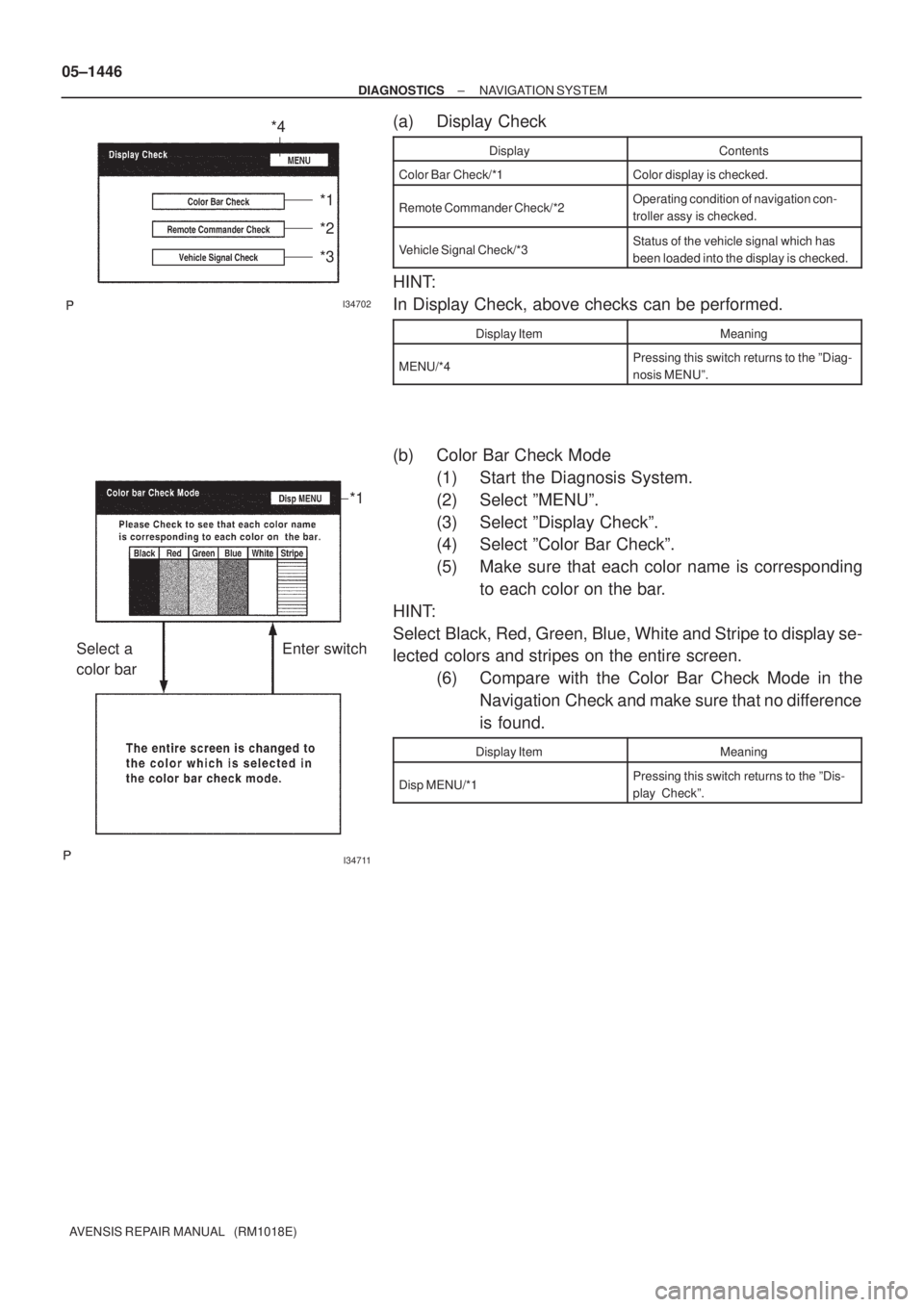
(a) Display Check
DisplayContents
Color Bar Check/*1Color display is checked.
Remote Commander Check/*2Operating condition of navigation con-
troller assy is checked.
Vehicle Signal Check/*3Status of the vehicle signal which has
been loaded into the display is checked.
HINT:
In Display Check, above checks can be performed.
Display ItemMeaning
MENU/*4Pressing this switch returns to the ºDiag-
nosis MENUº.
(b) Color Bar Check Mode
(1) Start the Diagnosis System.
(2) Select ºMENUº.
(3) Select ºDisplay Checkº.
(4) Select ºColor Bar Checkº.
(5) Make sure that each color name is corresponding
to each color on the bar.
HINT:
Select Black, Red, Green, Blue, White and Stripe to display se-
lected colors and stripes on the entire screen.
(6) Compare with the Color Bar Check Mode in the
Navigation Check and make sure that no difference
is found.
Display ItemMeaning
Disp MENU/*1Pressing this switch returns to the ºDis-
play Checkº.
Page 1520 of 5135
I34703
*1
*2
I34704
*1
± DIAGNOSTICSNAVIGATION SYSTEM
05±1447
AVENSIS REPAIR MANUAL (RM1018E)
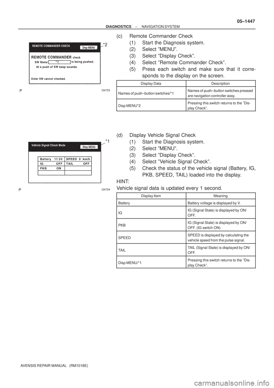
(c) Remote Commander Check
(1) Start the Diagnosis system.
(2) Select ºMENUº.
(3) Select ºDisplay Checkº.
(4) Select ºRemote Commander Checkº.
(5) Press each switch and make sure that it corre-
sponds to the display on the screen.
Display DataDescription
Names of push±button switches/*1Names of push±button switches pressed
are navigation controller assy.
Disp MENU*2Pressing this switch returns to the ºDis-
play Checkº.
(d) Display Vehicle Signal Check
(1) Start the Diagnosis system.
(2) Select ºMENUº.
(3) Select ºDisplay Checkº.
(4) Select ºVehicle Signal Checkº.
(5) Check the status of the vehicle signal (Battery, IG,
PKB, SPEED, TAIL) loaded into the display.
HINT:
Vehicle signal data is updated every 1 second.
Display ItemMeaning
BatteryBattery voltage is displayed by V.
IGIG (Signal State) is displayed by ON/
OFF.
PKBIG (Signal State) is displayed by ON/
OFF. (IG switch ON)
SPEEDSPEED is displayed by calculating the
vehicle speed from the pulse signal.
TAILTAIL (Signal State) is displayed by ON/
OFF.
Disp MENU/*1Pressing this switch returns to the ºDis-
play Checkº.
Page 1521 of 5135
I34694
HINT:
Memory Copy/Paste function is not available.Enter ºDIAGNOSIS
SYSTEM MODEº
(See section 4) 05±1448
± DIAGNOSTICSNAVIGATION SYSTEM
AVENSIS REPAIR MANUAL (RM1018E)
7. NAVIGATION CHECK MODE
Page 1522 of 5135
I34705
*1
*2
*3
*4*5*6
± DIAGNOSTICSNAVIGATION SYSTEM
05±1449
AVENSIS REPAIR MANUAL (RM1018E)
(a) Navigation Check
DisplayDescription
GPS Information/*1Information related to GPS is displayed
(updated every 1 second.).
Vehicle Sensors/*2
Vehicle signal information to be loaded in
the Navigation ECU is displayed (up-
dated every 1 second.).
Color Bar Check/*3
Color display of the Navigation ECU is
checked. (Compare with the Color Bar
Check results in the Display Check.)
Memory Copy / Paste/*4This function is not available.
Parts Information/*5Navigation program version and disc
version are displayed.
Menu/*6Pressing this switch returns to the ºDiag-
nosis MENUº.
HINT:
�In the Navigation Check, the checks mentioned above
can be conducted.
�The Navigation ECU operates each Navigation Check.
Page 1523 of 5135
I34706
*2
*5*2
*5
*6*1
*3*4
*7
05±1450
± DIAGNOSTICSNAVIGATION SYSTEM
AVENSIS REPAIR MANUAL (RM1018E)
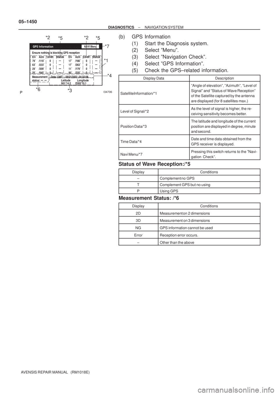
(b) GPS Information
(1) Start the Diagnosis system.
(2) Select ºMenuº.
(3) Select ºNavigation Checkº.
(4) Select ºGPS Informationº.
(5) Check the GPS±related information.
Display DataDescription
Satellite Information/*1
ºAngle of elevationº, ºAzimuthº, ºLevel of
Signalº and ºStatus of Wave Receptionº
of the Satellite captured by the antenna
are displayed (for 8 satellites max.)
Level of Signal/*2As the level of signal is higher, the re-
ceiving sensitivity becomes better.
Position Data/*3
The latitude and longitude of the current
position are displayed in degree, minute
and second.
Time Data/*4Date and time data obtained from the
GPS receiver is displayed.
Navi Menu/*7Pressing this switch returns to the ºNavi-
gation Checkº.
Status of Wave Reception:/*5
DisplayConditions
±Complement no GPS
TComplement GPS but no using
PUsing GPS
Measurement Status: /*6
DisplayConditions
2DMeasurement on 2 dimensions
3DMeasurement on 3 dimensions
NGGPS information cannot be used
ErrorReception error occurs.
±Other than the above
Page 1524 of 5135
I34707
*1
I34708
*1
I34709
*1
± DIAGNOSTICSNAVIGATION SYSTEM
05±1451
AVENSIS REPAIR MANUAL (RM1018E)
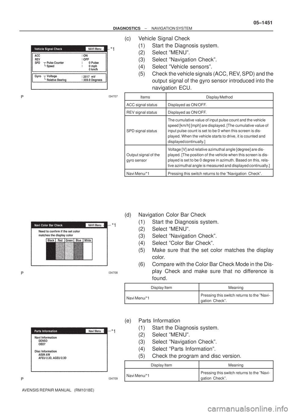
(c) Vehicle Signal Check
(1) Start the Diagnosis system.
(2) Select ºMENUº.
(3) Select ºNavigation Checkº.
(4) Select ºVehicle sensorsº.
(5) Check the vehicle signals (ACC, REV, SPD) and the
output signal of the gyro sensor introduced into the
navigation ECU.
ItemsDisplay Method
ACC signal statusDisplayed as ON/OFF.
REV signal statusDisplayed as ON/OFF.
SPD signal status
The cumulative value of input pulse count and the vehicle
speed [km/h] [mph] are displayed. [The cumulative value of
input pulse count is set to be 0 when this screen is dis-
played. When the vehicle starts to drive, it is counted and
displayed continually.]
Output signal of the
gyro sensor
Voltage [V] and relative azimuthal angle [degree] are dis-
played. [The position of the vehicle when this screen is dis-
played is set to be 0 degree in azimuth. Based on this, rela-
tive azimuthal angle is measured and displayed continually.]
Navi Menu/*1Pressing this switch returns to the ºNavigation Checkº.
(d) Navigation Color Bar Check
(1) Start the Diagnosis system.
(2) Select ºMENUº.
(3) Select ºNavigation Checkº.
(4) Select ºColor Bar Checkº.
(5) Make sure that the set color matches the display
color.
(6) Compare with the Color Bar Check Mode in the Dis-
play Check and make sure that no difference is
found.
Display ItemMeaning
Navi Menu/*1Pressing this switch returns to the ºNavi-
gation Checkº.
(e) Parts Information
(1) Start the Diagnosis system.
(2) Select ºMENUº.
(3) Select ºNavigation Checkº.
(4) Select ºParts Informationº.
(5) Check the program and disc version.
Display ItemMeaning
Navi Menu/*1Pressing this switch returns to the ºNavi-
gation Checkº.