Page 1485 of 5135
I34723
6
8N4 M2
7
12 3VG
R GB SYNC
VRR VG
G SYNC
VR B W
R G
Y18
3
7
26Navigation ECU
B M2
M2
M2
M2
M2(Shielded) Multi±display
(CRT Display) Display
N4
N4
N4
N4
N4
± DIAGNOSTICSNAVIGATION SYSTEM
05±1477
AVENSIS REPAIR MANUAL (RM1018E)
COLOR ON NAVIGATION SCREEN IS UNUSUAL (RGB SIGNAL
ERROR)
WIRING DIAGRAM
05C3M±01
Page 1486 of 5135

I35666
R
B
Multi±display (CRT Display) Display:
Navigation ECU: GVR
VG
G VGVR
B
R
M2
N4
05±1478
±
DIAGNOSTICS NAVIGATION SYSTEM
AVENSIS REPAIR MANUAL (RM1018E)
INSPECTION PROCEDURE
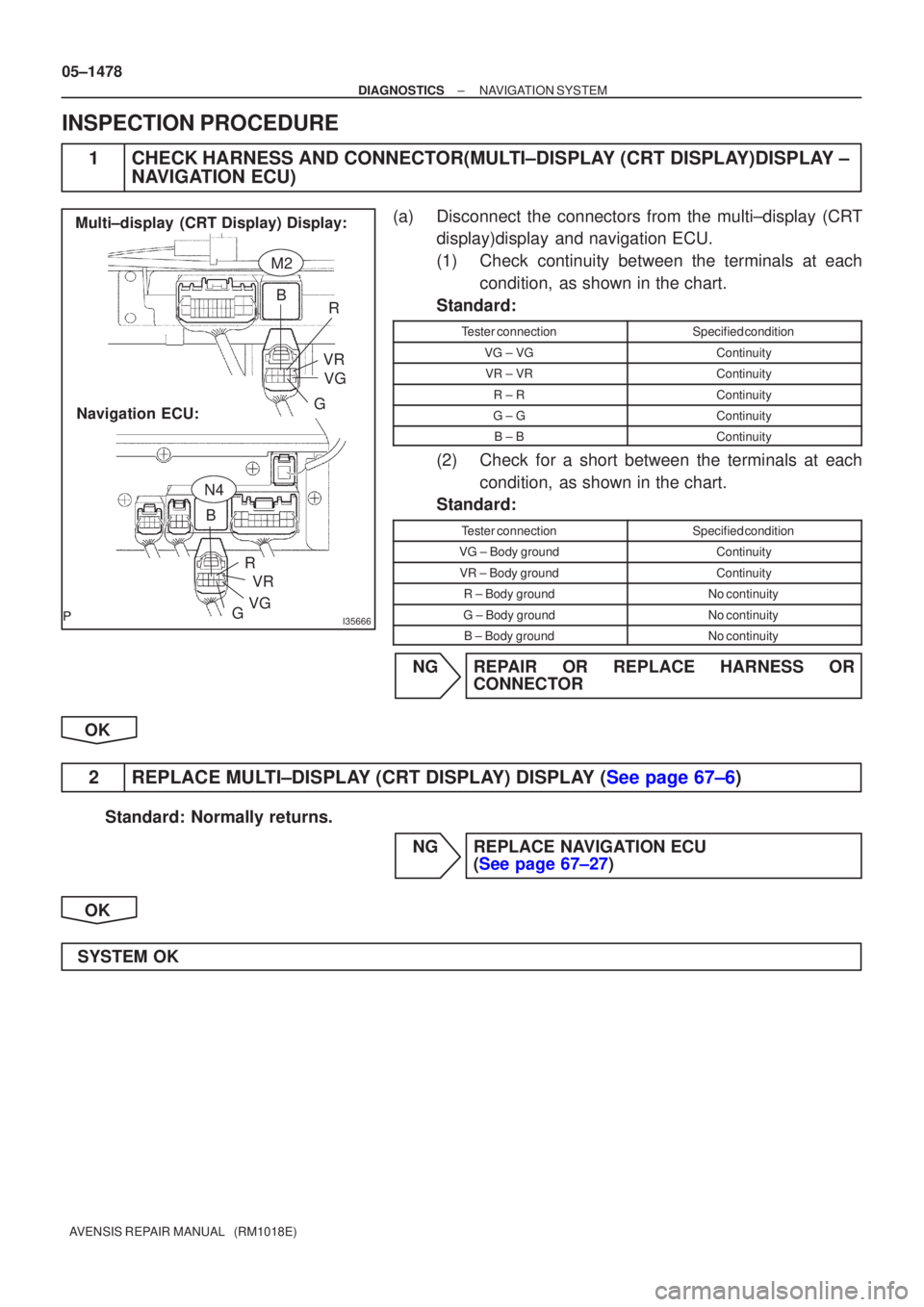
1CHECK HARNESS AND CONNECTOR(MULTI±DISPLAY (CRT DISPLAY)DISPLAY ± NAVIGATION ECU)
(a)Disconnect the connectors from the multi±display (CRT
display)display and navigation ECU.
(1)Check continuity between the terminals at each
condition, as shown in the chart.
Standard:
Tester connectionSpecified condition
VG ± VGContinuity
VR ± VRContinuity
R ± RContinuity
G ±GContinuity
B ± BContinuity
(2)Check for a short between the terminals at each condition, as shown in the chart.
Standard:
Tester connectionSpecified condition
VG ± Body groundContinuity
VR ± Body groundContinuity
R ± Body groundNo continuity
G ± Body groundNo continuity
B ± Body groundNo continuity
NGREPAIR OR REPLACE HARNESS OR CONNECTOR
OK
2REPLACE MULTI±DISPLAY (CRT DISPLAY) DISPLAY (See page 67±6)
Standard: Normally returns. NG REPLACE NAVIGATION ECU (See page 67±27)
OK
SYSTEM OK
Page 1487 of 5135
I34723
6
8N4 M2
7
12 3VG
R GB SYNC
VRR VG
G SYNC
VR B W
R G
Y18
3
7
26Navigation ECU
B M2
M2
M2
M2
M2(Shielded) Multi±display
(CRT Display) Display
N4
N4
N4
N4
N4
± DIAGNOSTICSNAVIGATION SYSTEM
05±1475
AVENSIS REPAIR MANUAL (RM1018E)
NAVIGATION SCREEN IS NOT STABILIZED (SYNCRONOUS
ERROR)
WIRING DIAGRAM
05C3L±01
Page 1488 of 5135
I35666
Multi±display (CRT Display) Display:Navigation ECU: SYNCVR
VG
SYNC VGVR
M2
N4
05±1476
±
DIAGNOSTICS NAVIGATION SYSTEM
AVENSIS REPAIR MANUAL (RM1018E)
INSPECTION PROCEDURE
1CHECK HARNESS AND CONNECTOR(MULTI±DISPLAY (CRT DISPLAY)DISPLAY ± NAVIGATION ECU)
(a)Disconnect the connectors from the multi±display (CRT
display)display and navigation ECU.
(1)Check continuity between the terminals at each
condition, as shown in the chart.
Standard:
Tester connectionSpecified condition
VG ± VGContinuity
VR ± VRContinuity
SYNC ± SYNCContinuity
(2)Check for a short between the terminals at each condition, as shown in the chart.
Standard:
Tester connectionSpecified condition
VG ± Body groundContinuity
VR ± Body groundContinuity
SYNC ± Body groundNo continuity
NGREPAIR OR REPLACE HARNESS OR CONNECTOR
OK
2REPLACE MULTI±DISPLAY (CRT DISPLAY) DISPLAY (See page 67±6)
Standard: Normally returns. NG REPLACE NAVIGATION ECU (See page 67±27)
OK
SYSTEM OK
Page 1489 of 5135
I34725
Multi±display
(CRT Display) Display
CTX±
CTX+
TX3+
TX3±
GTX+
GTX±M2
M1 M2
M1
M1
M110
5
12
24
5
18LG
V
G±Y
G
P
LG10
5Navigation ECU
Body ECU
(Combination Meter Assy)
Radio Receiver Assy3
4
9
10 C10
C10
R6
R6N4
N4TX±
TX+
TX± TX+
± DIAGNOSTICSNAVIGATION SYSTEM
05±1471
AVENSIS REPAIR MANUAL (RM1018E)
AVC±LAN CIRCUIT
WIRING DIAGRAM
INSPECTION PROCEDURE
1 INSPECT APPARATUS
(a) Choose the apparatus to be inspected.
ApparatusGo to step
Radio receiver assyA
Navigation ECUB
Body ECU (Combination Meter Assy)C
B Go to step 4
C Go to step 6
A
05C3K±01
Page 1490 of 5135

I35665
GTX+GTX±
TX+
TX±
Radio Receiver Assy: Multi±display (CRT Display) Display:
M2
R12
05±1472
±
DIAGNOSTICS NAVIGATION SYSTEM
AVENSIS REPAIR MANUAL (RM1018E)
2SERVICE CHECK MODE(RADIO RECEIVER ASSY)
(a)Perform the service check. (1)Start the diagnosis system and read the check result for the radio recei\
ver assy.
Standard:
AºNCONº is displayed or nothing is displayed (AUDIO H/U)
BºGOODº is displayed
BREPLACE MULTI±DISPLAY (CRT DISPLAY) DISPLAY (See page 67±6)
A
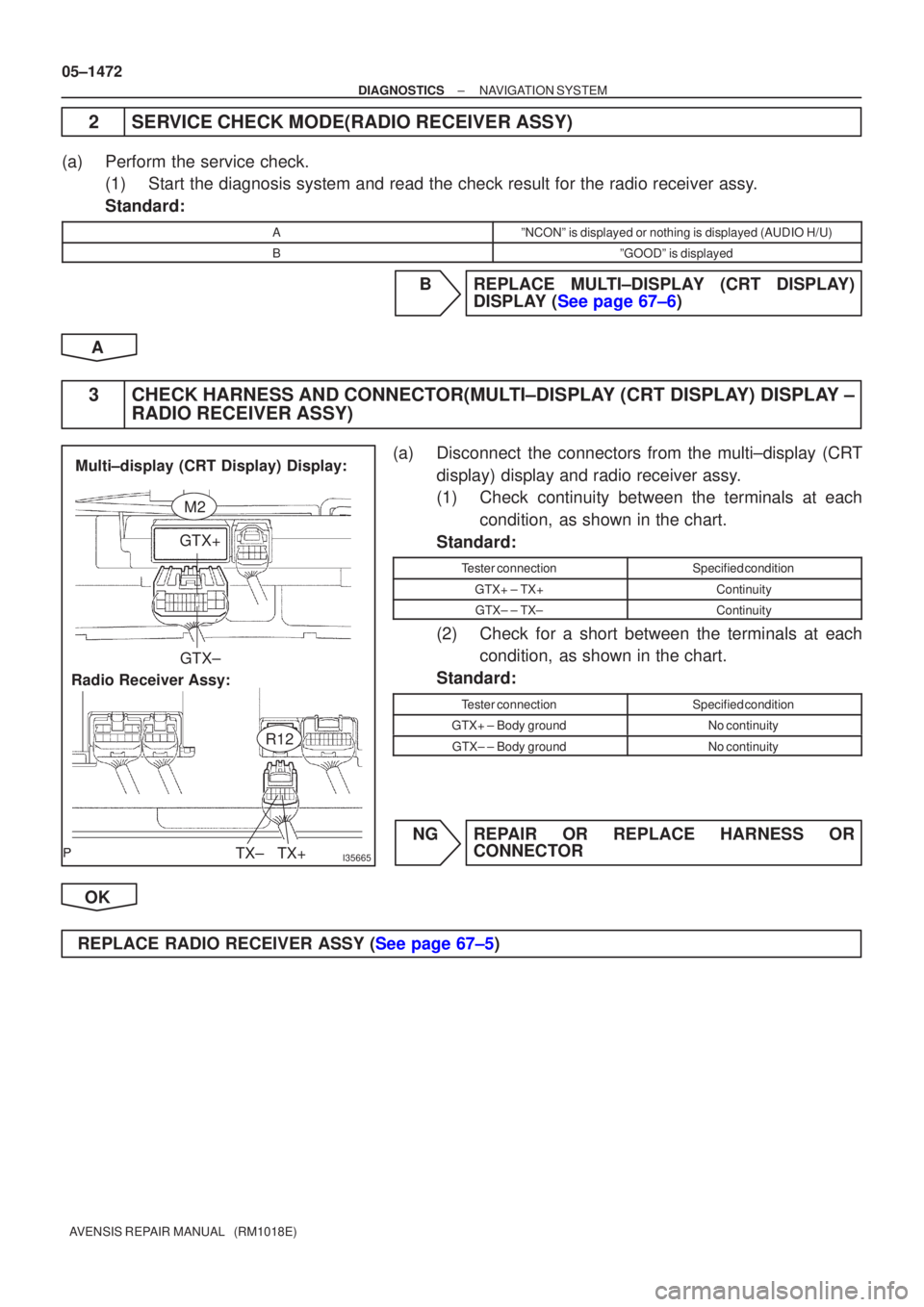
3CHECK HARNESS AND CONNECTOR(MULTI±DISPLAY (CRT DISPLAY) DISPLAY ± RADIO RECEIVER ASSY)
(a)Disconnect the connectors from the multi±display (CRT
display) display and radio receiver assy.
(1)Check continuity between the terminals at eachcondition, as shown in the chart.
Standard:
Tester connectionSpecified condition
GTX+ ± TX+Continuity
GTX± ± TX±Continuity
(2)Check for a short between the terminals at each condition, as shown in the chart.
Standard:
Tester connectionSpecified condition
GTX+ ± Body groundNo continuity
GTX± ± Body groundNo continuity
NGREPAIR OR REPLACE HARNESS OR CONNECTOR
OK
REPLACE RADIO RECEIVER ASSY (See page 67±5)
Page 1491 of 5135

I35666
CTX+CTX±
TX+
TX±
Navigation ECU: Multi±display (CRT Display) Display:
M3
N7
±
DIAGNOSTICS NAVIGATION SYSTEM
05±1473
AVENSIS REPAIR MANUAL (RM1018E)
4SERVICE CHECK MODE(NAVIGATION ECU)
(a)Perform the service check.
(1)Start the diagnosis system and read the check result for the navigation \
ECU.
Standard:
AºNCONº is displayed or nothing display (NAVI)
BºGOODº is display
BREPLACE MULTI±DISPLAY (CRT DISPLAY) DISPLAY (See page 67±6)
A
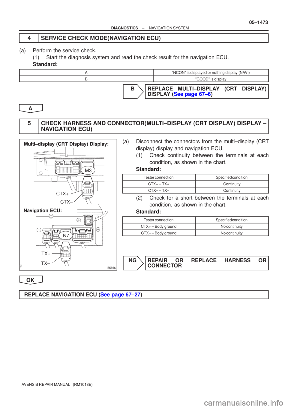
5CHECK HARNESS AND CONNECTOR(MULTI±DISPLAY (CRT DISPLAY) DISPLAY ± NAVIGATION ECU)
(a)Disconnect the connectors from the multi±display (CRT
display) display and navigation ECU.
(1)Check continuity between the terminals at eachcondition, as shown in the chart.
Standard:
Tester connectionSpecified condition
CTX+ ± TX+Continuity
CTX± ± TX±Continuity
(2)Check for a short between the terminals at each condition, as shown in the chart.
Standard:
Tester connectionSpecified condition
CTX+ ± Body groundNo continuity
CTX± ± Body groundNo continuity
NGREPAIR OR REPLACE HARNESS OR CONNECTOR
OK
REPLACE NAVIGATION ECU (See page 67±27)
Page 1492 of 5135

I35875
Multi±display (CRT Display) Display:Body ECU (Combination Meter Assy): TX3+
TX3± GTX+
GTX±
M1
C10
05±1474
±
DIAGNOSTICS NAVIGATION SYSTEM
AVENSIS REPAIR MANUAL (RM1018E)
6SERVICE CHECK MODE(BODY ECU)
(a)Perform the service check. (1)Start the diagnosis system and read check result for body ECU.
Standard:
AºNCONº is displayed or nothing display (BODY)
BºGOODº is display
BREPLACE MULTI±DISPLAY (CRT DISPLAY) DISPLAY (See page 67±6)
A
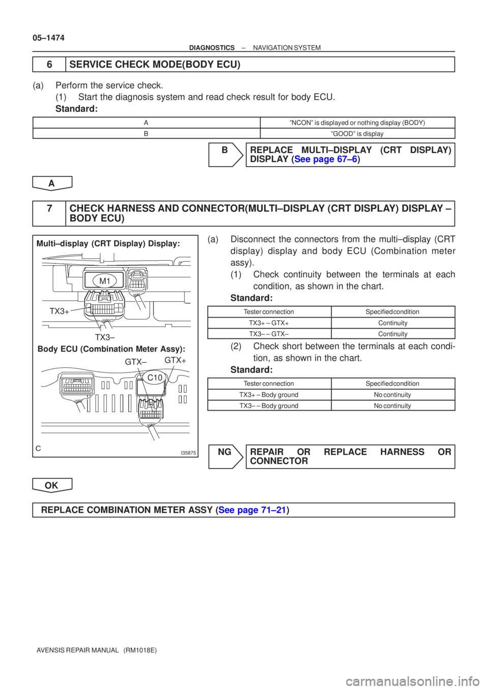
7CHECK HARNESS AND CONNECTOR(MULTI±DISPLAY (CRT DISPLAY) DISPLAY ± BODY ECU)
(a)Disconnect the connectors from the multi±display (CRT
display) display and body ECU (Combination meter
assy).
(1)Check continuity between the terminals at eachcondition, as shown in the chart.
Standard:
Tester connectionSpecified condition
TX3+ ± GTX+Continuity
TX3± ± GTX±Continuity
(2)Check short between the terminals at each condi- tion, as shown in the chart.
Standard:
Tester connectionSpecified condition
TX3+ ± Body groundNo continuity
TX3± ± Body groundNo continuity
NGREPAIR OR REPLACE HARNESS OR CONNECTOR
OK
REPLACE COMBINATION METER ASSY (See page 71±21)