Page 1921 of 5135
A09656
A79144
A80110
±
FUEL INJECTOR ASSY(1CD±FTV)
11±61
AVENSIS REPAIR MANUAL (RM1018E)
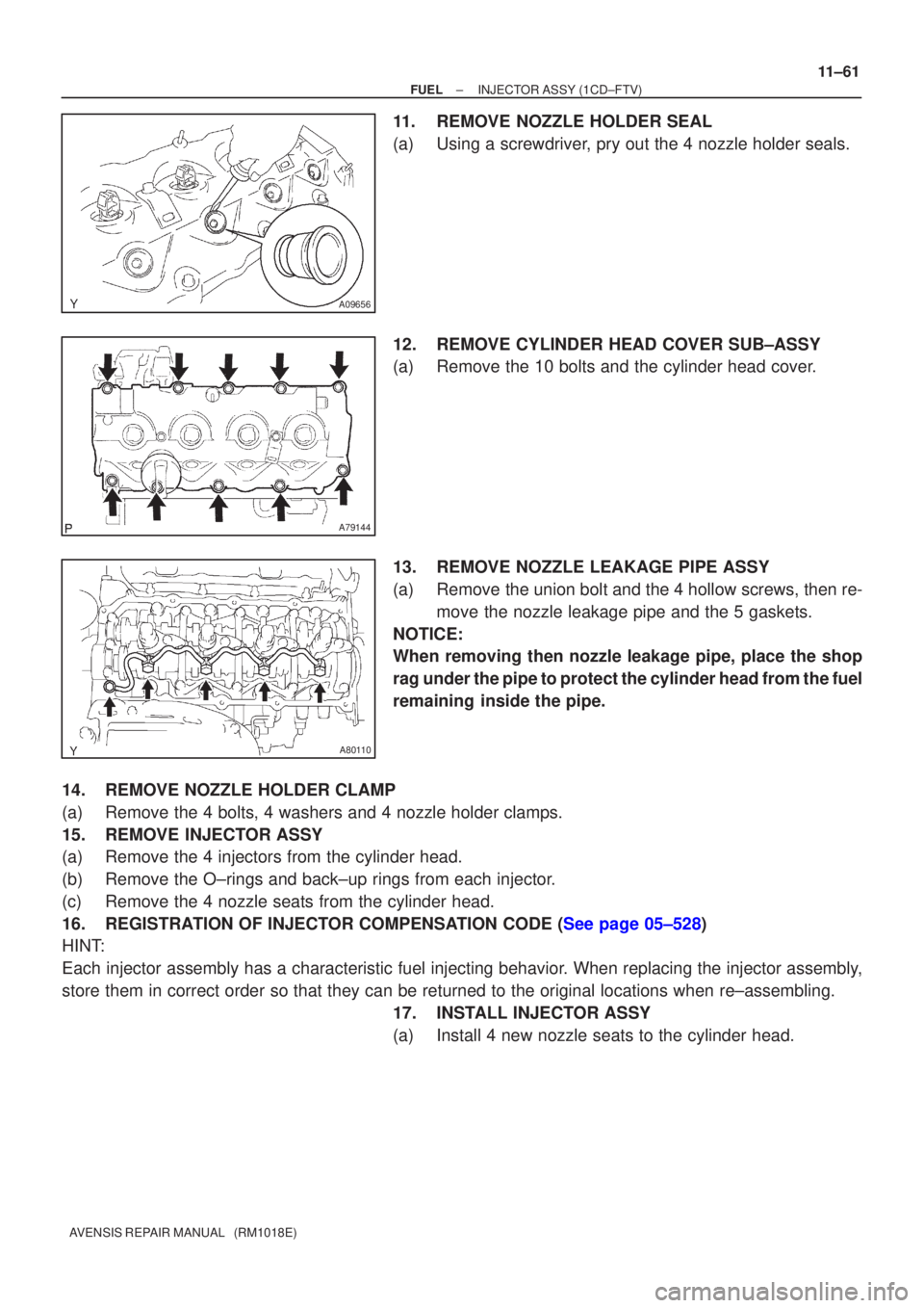
11.REMOVE NOZZLE HOLDER SEAL
(a)Using a screwdriver, pry out the 4 nozzle holder seals.
12.REMOVE CYLINDER HEAD COVER SUB±ASSY
(a)Remove the 10 bolts and the cylinder head cover.
13.REMOVE NOZZLE LEAKAGE PIPE ASSY
(a)Remove the union bolt and the 4 hollow screws, then re-
move the nozzle leakage pipe and the 5 gaskets.
NOTICE:
When removing then nozzle leakage pipe, place the shop
rag under the pipe to protect the cylinder head from the fuel
remaining inside the pipe.
14.REMOVE NOZZLE HOLDER CLAMP
(a)Remove the 4 bolts, 4 washers and 4 nozzle holder clamps.
15.REMOVE INJECTOR ASSY
(a)Remove the 4 injectors from the cylinder head.
(b)Remove the O±rings and back±up rings from each injector.
(c)Remove the 4 nozzle seats from the cylinder head.
16.REGISTRATION OF INJECTOR COMPENSATION CODE (See page 05±528)
HINT:
Each injector assembly has a characteristic fuel injecting behavior. When replacing the injector assembly,
store them in correct order so that they can be returned to the original\
locations when re±assembling. 17. INSTALL INJECTOR ASSY
(a) Install 4 new nozzle seats to the cylinder head.
Page 2921 of 5135
I35431
Burner Motor
Glow Plug
Surface Sensor
Temp. Control Sensor
Flame Sensor13
Power
Heater
ECU
Connector BTerminal L
of AlternatorBattery
Metering Pump
Fuse (20 A)
Vehicle Side SW 14
9
12
5
6
3
4
1
2R
BR
B±R
G
L±Y
L
Y
L±W5
1
6
2
7
3
8
4W±B
R±G
R±B Connector A
IG
W±R (*1)
Y±R (*2)
R±L (*1)
R±Y (*2)
*1: TMC Made
*2: TMUK Made 55±16
± HEATER & AIR CONDITIONERCOMBUSTION TYPE POWER HEATER SYSTEM
AVENSIS REPAIR MANUAL (RM1018E)
2. DESCRIPTION OF DISPLAY AND BUTTONS
(a) AF: Current Value Malfunction (Blinking at current failure)
Diag: DTC (Example: 064 Flame sensor break)
Memory Clear button: Deletion of faulty memory (Press both buttons together for longer than 2 se-
conds)
> Button: Scroll up of faulty memory (The past 5 codes can be stored.)
< Button: Scroll down of faulty memory (The past 5 codes can be stored.)
3. FAULTY MEMORY
(a) The ECU is able to store up to 5 pieces of faulty memory. If it is full, the new data is written over F5.
4. WIRING DIAGRAM
Page 2922 of 5135
± HEATER & AIR CONDITIONERCOMBUSTION TYPE POWER HEATER SYSTEM
55±17
AVENSIS REPAIR MANUAL (RM1018E)
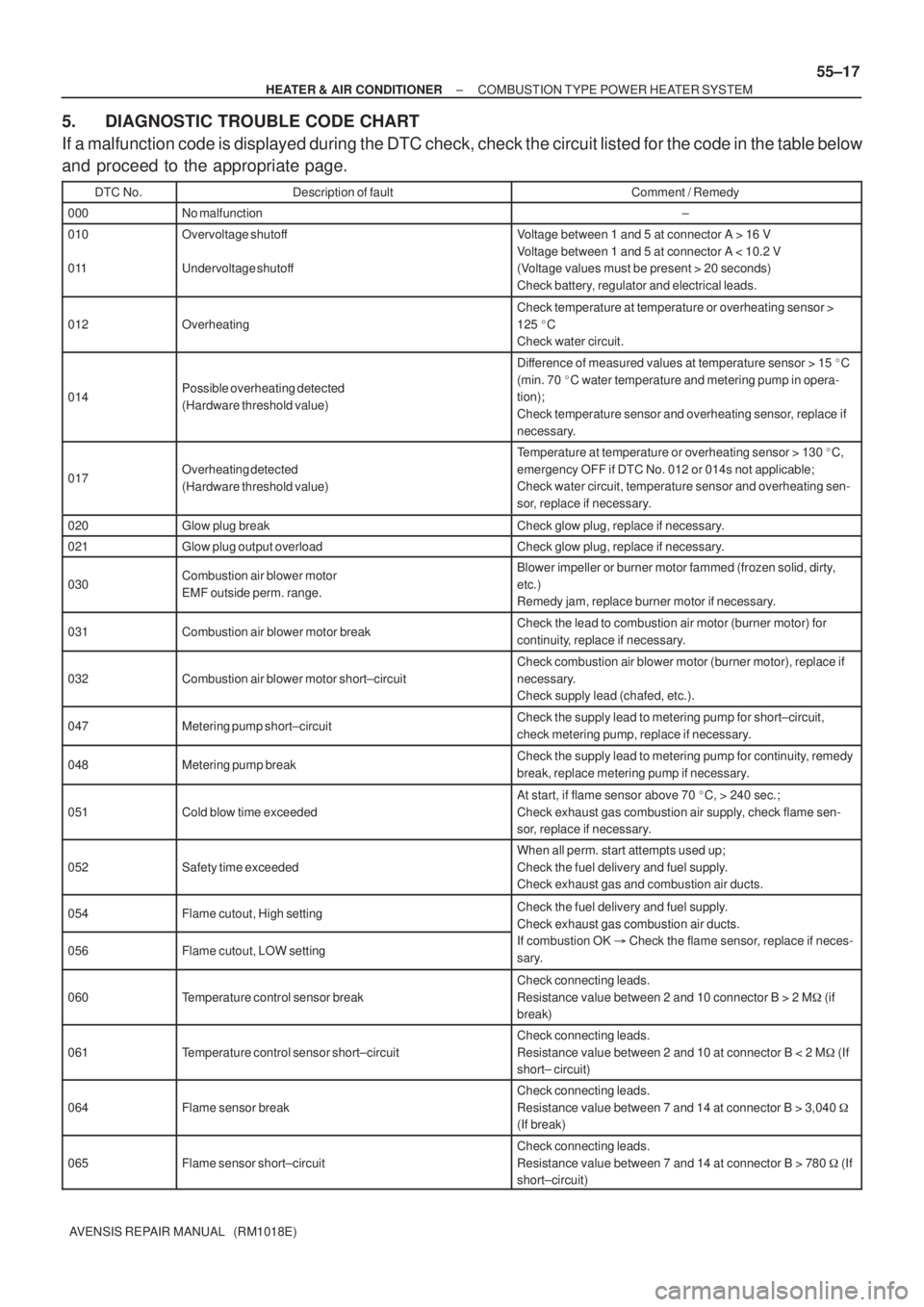
5. DIAGNOSTIC TROUBLE CODE CHART
If a malfunction code is displayed during the DTC check, check the circuit listed for the code in the table below
and proceed to the appropriate page.
DTC No.Description of faultComment / Remedy
000No malfunction±
010
011Overvoltage shutoff
Undervoltage shutoffVoltage between 1 and 5 at connector A > 16 V
Voltage between 1 and 5 at connector A < 10.2 V
(Voltage values must be present > 20 seconds)
Check battery, regulator and electrical leads.
012Overheating
Check temperature at temperature or overheating sensor >
125 �C
Check water circuit.
014Possible overheating detected
(Hardware threshold value)
Difference of measured values at temperature sensor > 15 �C
(min. 70 �C water temperature and metering pump in opera-
tion);
Check temperature sensor and overheating sensor, replace if
necessary.
017Overheating detected
(Hardware threshold value)
Temperature at temperature or overheating sensor > 130 �C,
emergency OFF if DTC No. 012 or 014s not applicable;
Check water circuit, temperature sensor and overheating sen-
sor, replace if necessary.
020Glow plug breakCheck glow plug, replace if necessary.
021Glow plug output overloadCheck glow plug, replace if necessary.
030Combustion air blower motor
EMF outside perm. range.Blower impeller or burner motor fammed (frozen solid, dirty,
etc.)
Remedy jam, replace burner motor if necessary.
031Combustion air blower motor breakCheck the lead to combustion air motor (burner motor) for
continuity, replace if necessary.
032Combustion air blower motor short±circuit
Check combustion air blower motor (burner motor), replace if
necessary.
Check supply lead (chafed, etc.).
047Metering pump short±circuitCheck the supply lead to metering pump for short±circuit,
check metering pump, replace if necessary.
048Metering pump breakCheck the supply lead to metering pump for continuity, remedy
break, replace metering pump if necessary.
051Cold blow time exceeded
At start, if flame sensor above 70 �C, > 240 sec.;
Check exhaust gas combustion air supply, check flame sen-
sor, replace if necessary.
052Safety time exceeded
When all perm. start attempts used up;
Check the fuel delivery and fuel supply.
Check exhaust gas and combustion air ducts.
054Flame cutout, High settingCheck the fuel delivery and fuel supply.
Check exhaust gas combustion air ducts.
056Flame cutout, LOW setting
Check exhaust gas combustion air ducts.
If combustion OK � Check the flame sensor, replace if neces-
sary.
060Temperature control sensor break
Check connecting leads.
Resistance value between 2 and 10 connector B > 2 M� (if
break)
061Temperature control sensor short±circuit
Check connecting leads.
Resistance value between 2 and 10 at connector B < 2 M� (If
short± circuit)
064Flame sensor break
Check connecting leads.
Resistance value between 7 and 14 at connector B > 3,040 �
(If break)
065Flame sensor short±circuit
Check connecting leads.
Resistance value between 7 and 14 at connector B > 780 � (If
short±circuit)
Page 3221 of 5135
Page 3309 of 5135
730EY±02
± THEFT DETERRENT & DOOR LOCKTRANSMITTER SUB±ASSY MODULE SET DOOR
CONTROL73±21
AVENSIS REPAIR MANUAL (RM1018E)
REGISTRATION
1. REGISTER RECOGNITION CODE
HINT:
�Register the recognition code when replacing the door control transmitter or the door control receiverr.
�The add mode is used to register new recognition codes while still retaining codes already registered.
This mode is used when a new transmitter is added. If the number of registered codes exceeds 4, the
previously registered codes will be erased in order, starting from the first registered code.
�The rewrite mode is used to erase all the previously registered recognition codes in order to register
new recognition codes. This mode is used when the transmitter or the door control receiver is ex-
changed for a new one.
�The confirmation mode is used to confirm how many recognition codes have already been registered
before an additional registration of a recognition codes.
�The all clear mode is used to erase all the registered codes and disables the wireless door lock func-
tion. This mode is used when the transmitter is lost.
�All the following registration procedures must be performed in order continuously.
Page 3310 of 5135
Within 5 sec.
Within 40 sec.
Continued on next page 1.
2.
3.
4.
5.
6.Insert key into ignition key cylinder, then pull it out.
Close and open driver side door twice.
Close and open driver side door twice.
Insert key into ignition key cylinder and close all doors.
START
Insert key into ignition key cylinder, then pull it out.
Insert key into ignition key cylinder, then pull it out.
Flow Chart of Recognition Code Registration
Within 40 sec.
Within 40 sec.Make sure that the following conditions are met.
�
No key in ignition key cylinder.
� Driver side door is open (Other doors are closed).
�
Driver side door is unlocked. 73±22
± THEFT DETERRENT & DOOR LOCKTRANSMITTER SUB±ASSY MODULE SET DOOR
CONTROL
AVENSIS REPAIR MANUAL (RM1018E)
Page 3312 of 5135
Continued from previous page
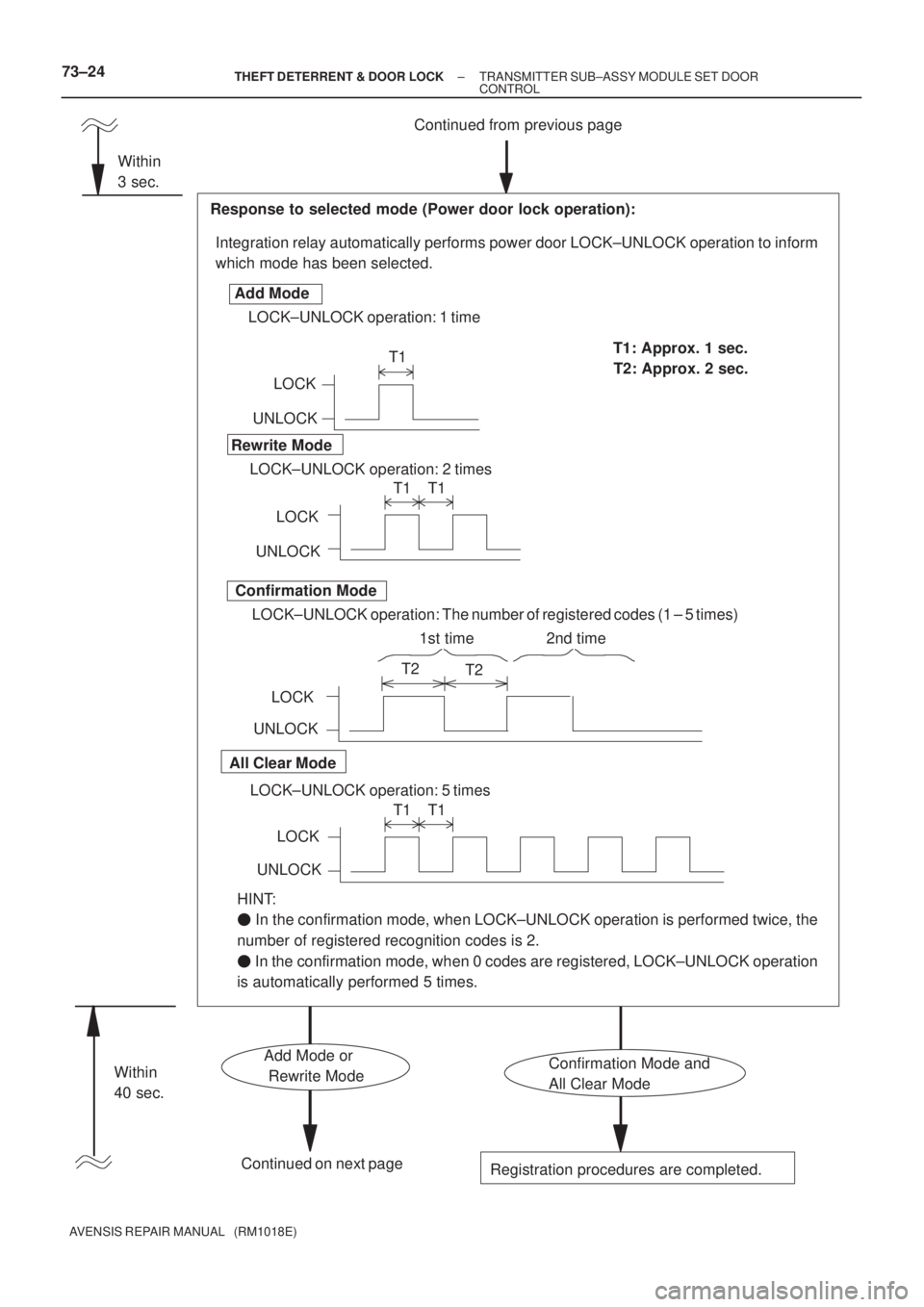
Integration relay automatically performs power door LOCK±UNLOCK operation to inform
which mode has been selected.
Response to selected mode (Power door lock operation):
UNLOCKLOCK
LOCK±UNLOCK operation: 1 time Add Mode
Rewrite Mode
Confirmation Mode
All Clear Mode
T1T1: Approx. 1 sec.
T1 T1
T2
T2
T1 T1
LOCK±UNLOCK operation: 2 times
LOCK±UNLOCK operation: The number of registered codes (1 ± 5 times)
LOCK±UNLOCK operation: 5 timesUNLOCKLOCK
UNLOCKLOCK
UNLOCKLOCK
Continued on next page
Registration procedures are completed.
HINT:
� In the confirmation mode, when LOCK±UNLOCK operation is performed twice, the
number of registered recognition codes is 2.
� In the confirmation mode, when 0 codes are registered, LOCK±UNLOCK operation
is automatically performed 5 times.T2: Approx. 2 sec.
Confirmation Mode and
All Clear ModeAdd Mode or
Rewrite Mode Within
3 sec.
Within
40 sec.
1st time 2nd time
73±24± THEFT DETERRENT & DOOR LOCKTRANSMITTER SUB±ASSY MODULE SET DOOR
CONTROL
AVENSIS REPAIR MANUAL (RM1018E)
Page 3313 of 5135
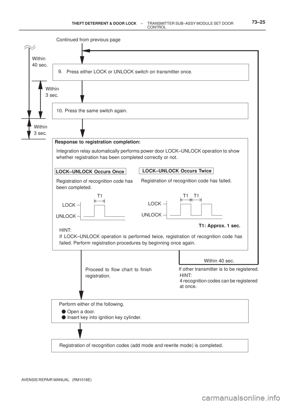
Continued from previous page
Press either LOCK or UNLOCK switch on transmitter once. 9.
Within 40 sec.
Proceed to flow chart to finish
registration.
Press the same switch again.
LOCK±UNLOCK Occurs Once
Registration of recognition code has
been completed. Response to registration completion:
T1: Approx. 1 sec. LOCK±UNLOCK Occurs Twice
Registration of recognition code has failed. 10.
LOCK
UNLOCK
T1
LOCK
UNLOCKT1 T1
Within
40 sec.
If other transmitter is to be registered. Within
3 sec.
Registration of recognition codes (add mode and rewrite mode) is completed.
Integration relay automatically performs power door LOCK±UNLOCK operation to show
whether registration has been completed correctly or not.
HINT:
4 recognition codes can be registered
at once. HINT:
If LOCK±UNLOCK operation is performed twice, registration of recognition code has
failed. Perform registration procedures by beginning once again.
Within
3 sec.
� Open a door.
� Insert key into ignition key cylinder. Perform either of the following.
± THEFT DETERRENT & DOOR LOCKTRANSMITTER SUB±ASSY MODULE SET DOOR
CONTROL73±25
AVENSIS REPAIR MANUAL (RM1018E)