Page 1683 of 5135
05±1618
±
DIAGNOSTICS ENGINE IMMOBILISER SYSTEM
AVENSIS REPAIR MANUAL (RM1018E)
DTC B2793 TRANSPONDER CHIP MALFUNCTION
CIRCUIT DESCRIPTION
This DTC is output when a malfunction is found in a key during the key code \
registration or the key code
is not registered normally. Replace the key when the key code registration is not performed normal\
ly and
this DTC is detected.
DTC No.DTC Detection ConditionTrouble Area
B2793Transponder chip malfunction� Key
INSPECTION PROCEDURE
1 CHECK DTC
(a)Delete the DTC (See page 05±1602).
(b) Insert the key into the ignition key cylinder.
(c) Check that no code is output.
OK NO PROBLEM
NG
2 RE±REGISTER KEY
(a)Delete the DTC (See page 05±1602).
(b) Re±register the key and check that the engine starts with the key. OK NORMAL
NG
REPLACE KEY
05B0E±03
Page 1684 of 5135

B62676
I12
Transponder Key AmplifierT8
Transponder Key ECU Assy
VC5
CODE
TXCT
AGND Y±B
Y±G
L±R
GR±R8
11
12
13 1
4
5
7 TXCT
GND
ANT2 ANT1 VC5
CODE
CoilAmplifier
05±1616
± DIAGNOSTICSENGINE IMMOBILISER SYSTEM
AVENSIS REPAIR MANUAL (RM1018E)
DTC B2784 ANTENNA COIL OPEN/SHORT
CIRCUIT DESCRIPTION
The transponder key coil is built into the transponder key amplifier and receives a key code signal from the
transponder chip in the key. This signal is amplified by the amplifier and then output to the transponder key
ECU.
DTC No.DTC Detection ConditionTrouble Area
B2784Antenna coil is open/short
�Wire harness
�Transponder key amplifier
�Transponder key ECU assy
WIRING DIAGRAM
INSPECTION PROCEDURE
HINT:
Start the inspection from step 1 when using the hand±held tester and start from step 2 when not using the
hand±held tester.
1 READ VALUE OF HAND±HELD TESTER
(IMMOBILISER ECU (TRANSPONDER KEY ECU ASSY) (SWITCH CONDITION))
(a) Connect the hand±held tester to the DLC3.
(b) Turn the ignition switch ON with the key that will not start the engine.
(c) Select the item ANTENNA COIL on the hand±held tester.
OK: NORMAL
NG: FAIL
OK CHECK AND REPLACE TRANSPONDER KEY
ECU ASSY
NG
05B0D±03
Page 1685 of 5135
������
��� ����
������B64974
I12
Transponder Key Amplifier Wire Harness Side
T8
Transponder Key ECU Assy
± DIAGNOSTICSENGINE IMMOBILISER SYSTEM
05±1617
AVENSIS REPAIR MANUAL (RM1018E)
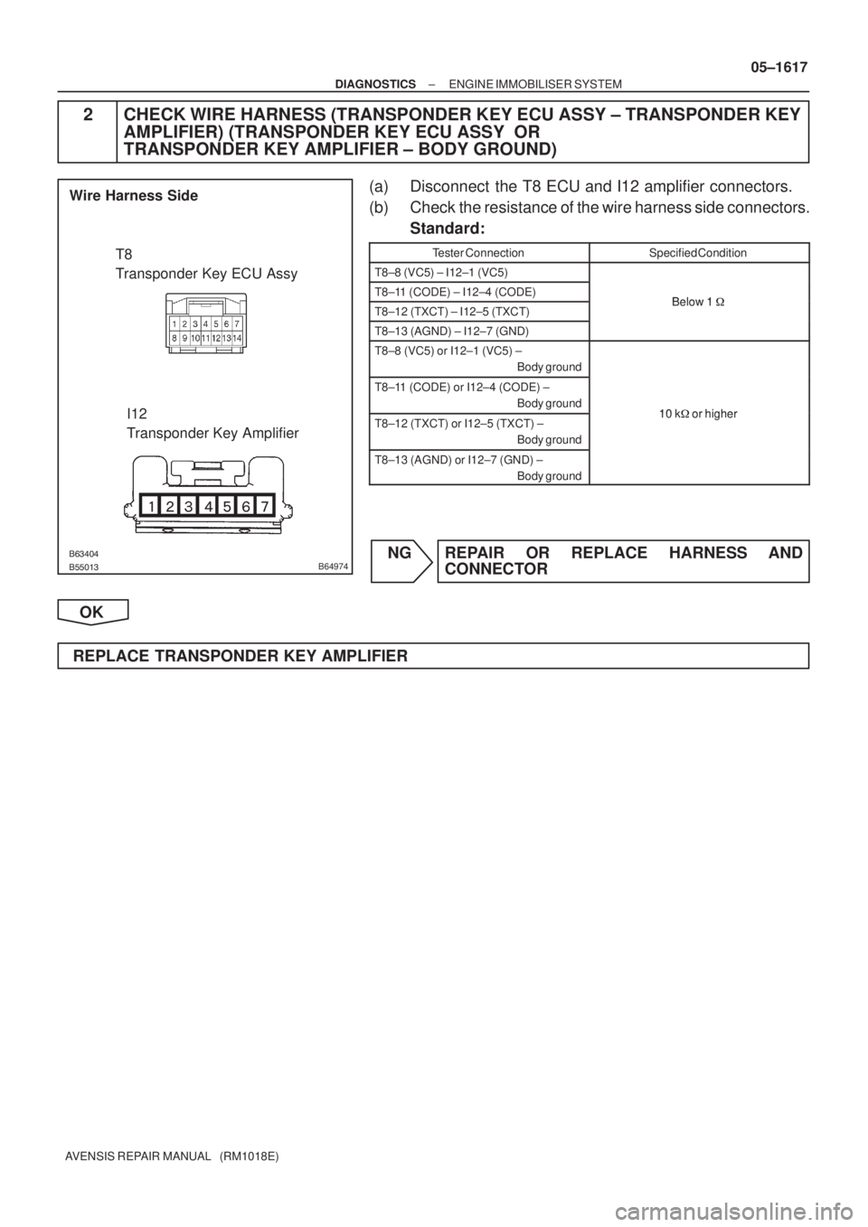
2 CHECK WIRE HARNESS (TRANSPONDER KEY ECU ASSY ± TRANSPONDER KEY
AMPLIFIER) (TRANSPONDER KEY ECU ASSY OR
TRANSPONDER KEY AMPLIFIER ± BODY GROUND)
(a) Disconnect the T8 ECU and I12 amplifier connectors.
(b) Check the resistance of the wire harness side connectors.
Standard:
Tester ConnectionSpecified Condition
T8±8 (VC5) ± I12±1 (VC5)
T8±11 (CODE) ± I12±4 (CODE)Below 1�T8±12 (TXCT) ± I12±5 (TXCT)Below 1 �
T8±13 (AGND) ± I12±7 (GND)
T8±8 (VC5) or I12±1 (VC5) ±
Body ground
T8±11 (CODE) or I12±4 (CODE) ±
Body ground
10 k�or higherT8±12 (TXCT) or I12±5 (TXCT) ±
Body ground10 k� or higher
T8±13 (AGND) or I12±7 (GND) ±
Body ground
NG REPAIR OR REPLACE HARNESS AND
CONNECTOR
OK
REPLACE TRANSPONDER KEY AMPLIFIER
Page 1725 of 5135

DIAGNOSTIC TROUBLE CODE CHART
If a malfunction code is displayed during the DTC check, check the circ")
05AEQ±02
05±1656
±
DIAGNOSTICS MULTIPLEX COMMUNICATION SYSTEM
AVENSIS REPAIR MANUAL (RM1018E)
DIAGNOSTIC TROUBLE CODE CHART
If a malfunction code is displayed during the DTC check, check the circuit\
listed for that code in the chart
below (Proceed to the page given for that circuit).
DTC No.
(See Page)Detection ItemTrouble Area
B1214
(05±1670)Door System Communication Bus Malfunction (+B Short)
� Wire harness
� ECM
� A/C control assy (A/C ECU)
� Theft warning ECU assy
� Combination meter assy (Combination meter ECU)
� Instrument panel J/B assy (Integration relay)
B1215
(05±1670)Door System Communication Bus Malfunction (GND Short)
� Wire harness
� ECM
� A/C control assy (A/C ECU)
� Theft warning ECU assy
� Combination meter assy (Combination meter ECU)
� Instrument panel J/B assy (Integration relay)
B1261
(05±1680)ECM Communication Stop� Wire harness
� ECM
B1262
(05±1685)A/C ECU Communication Stop� Wire harness
� A/C assy (A/C ECU)
B1269
(05±1689)Theft Deterrent ECU Communication Stop� Wire harness
� Theft warning ECU assy
B1271
(05±1693)Combination Meter ECU Communication Stop� Wire harness
� Combination meter assy (Combination meter ECU)
Page 1727 of 5135
05AEO±02
05±1654
±
DIAGNOSTICS MULTIPLEX COMMUNICATION SYSTEM
AVENSIS REPAIR MANUAL (RM1018E)
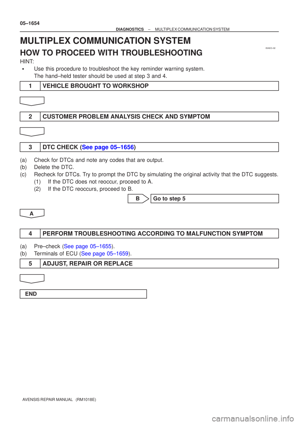
MULTIPLEX COMMUNICATION SYSTEM
HOW TO PROCEED WITH TROUBLESHOOTING
HINT:
�Use this procedure to troubleshoot the key reminder warning system.
The hand±held tester should be used at step 3 and 4.
1VEHICLE BROUGHT TO WORKSHOP
2CUSTOMER PROBLEM ANALYSIS CHECK AND SYMPTOM
3DTC CHECK (See page 05±1656)
(a)Check for DTCs and note any codes that are output.
(b)Delete the DTC.
(c)Recheck for DTCs. Try to prompt the DTC by simulating the original activity that the DTC su\
ggests. (1)If the DTC does not reoccur, proceed to A.
(2)If the DTC reoccurs, proceed to B.
BGo to step 5
A
4PERFORM TROUBLESHOOTING ACCORDING TO MALFUNCTION SYMPTOM
(a)Pre±check (See page 05±1655).
(b)Terminals of ECU (See page 05±1659).
5 ADJUST, REPAIR OR REPLACE
END
Page 1757 of 5135
±
DIAGNOSTICS CRUISE CONTROL SYSTEM
05±1717
AVENSIS REPAIR MANUAL (RM1018E)
DTC P0607/54 CONTROL MODULE PERFORMANCE
CIRCUIT DESCRIPTION
This DTC indicates the internal abnormalities of ECM.
DTC No.Detection ItemTrouble Area
P0607/54
The ECM has a supervisory CPU and control ECU inside.
When each input STP signal is different for 0.15 sec. or more,
the malfunction code is output.
The malfunction code is output after 0.4 sec. have passed from
the time the cruise cancel input signal (STP input) is input into
the ECM.
HINT:
�When a malfunction code is detected, the fail safe must be
kept on until the ignition switch is turned off.
�ECM
INSPECTION PROCEDURE
1REPLACE ECM (See page 01±32)
05C4S±01
Page 1758 of 5135

DTC P0571/52 BRAKE SWITCH ºAº CIRCUIT
CIRCUIT DESCRIPTION
When the brake pedal is depressed, the stop lamp switch assy")
± DIAGNOSTICSCRUISE CONTROL SYSTEM
05±1711
AVENSIS REPAIR MANUAL (RM1018E)
DTC P0571/52 BRAKE SWITCH ºAº CIRCUIT
CIRCUIT DESCRIPTION
When the brake pedal is depressed, the stop lamp switch assy sends a signal to the ECM. When the ECM
receives this signal, it cancels the cruise control.
A fail±safe function is provided so that it functions normally, even if there is a malfunction in the stop lamp
signal circuit.
The cancel condition occurs when battery positive voltage is supplied to terminal STP.
When the brake is on, battery positive voltage is normally applied through the STOP fuse and the stop lamp
switch assy to terminal STP of the ECM, and the ECM turns the cruise control OFF.
If the harness connected to terminal STP has an open circuit, terminal STP will have battery positive voltage
and the cruise control will be turned OFF.
DTC No.DTC Detection ConditionTrouble Area
P0571/52
The malfunction code is output when the voltage of the STP
terminal and that of the ST1 terminal on the ECM are less than
1 V for 0.5 sec. or more.
When the following conditions are realized, a malfunction is
detected.
�The STP terminal voltage is less than 1 V.
�The ST1 terminal voltage is less than 1 V.
�For more than 0.5 sec. or more.
�Stop lamp switch assy
�Stop lamp switch assy circuit
�ECM
05C4R±01
Page 1764 of 5135
05±1710
±
DIAGNOSTICS CRUISE CONTROL SYSTEM
AVENSIS REPAIR MANUAL (RM1018E)
DTC P0500/21 VEHICLE SPEED SENSOR ºAº
DTC P0503/23 VEHICLE SPEED SENSOR ºAº INTERMITTENT/ERRATIC/HIGH
CIRCUIT DESCRIPTION
See page 05±453. (1AZ±FSE) See page 05±640. (1CD±FTV)
DTC No.DTC Detection ConditionTrouble Area
P0500/21
The malfunction code is output when the vehicle speed signal
from the vehicle speed sensor is cut for 0.14 sec. or more
while cruise control is in operation.
�Combination meter
� Vehicle speed sensor
P0503/23
Momentary interruption and noise malfunction codes are output
when a rapid change of vehicle speed occurs while cruise
control is in operation.
Vehicle s eed sensor
�Vehicle speed sensor
� ECM
WIRING DIAGRAM
See page 05±453. (1AZ±FSE) See page 05±640. (1CD±FTV)
INSPECTION PROCEDURE
See page 05±453. (1AZ±FSE) See page 05±640. (1CD±FTV)
05C4Q±01

DTC B2793 TRANSPONDER CHIP MALFUNCTION
CIRCUIT DESCRIPTION
This DTC is output when a malfunction is found in a key d")

DTC P0607/54 CONTROL MODULE PERFORMANCE
CIRCUIT DESCRIPTION
This DTC indicates the internal abnormalities of ECM.
DTC No")

DTC P0500/21 VEHICLE SPEED SENSOR ºAº
DTC P0503/23 VEHICLE SPEED SENSOR ºAº INTERMITTENT/ERRATIC/HIGH
CIRCUIT DESCRI")