Page 1765 of 5135
056HK±05
±
DIAGNOSTICS CRUISE CONTROL SYSTEM
05±1709
AVENSIS REPAIR MANUAL (RM1018E)
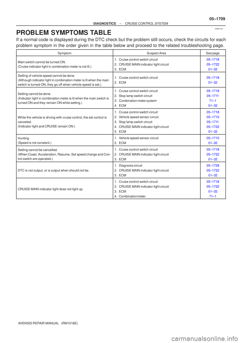
PROBLEM SYMPTOMS TABLE
If a normal code is displayed during the DTC check but the problem still o\
ccurs, check the circuits for each
problem symptom in the order given in the table below and proceed to the relate\
d troubleshooting page.
SymptomSuspect AreaSee page
Main switch cannot be turned ON.
(Cruise indicator light in combination meter is not lit.)1. Cruise control switch circuit
2. CRUISE MAIN indicator light circuit
3. ECM05±1718
05±1722
01±32
Setting of vehicle speed cannot be done.
(Although indicator light in combination meter is lit when the main
switch is turned ON, they go off when vehicle speed is set.)1. Cruise control switch circuit
2. ECM05±171801±32
Setting cannot be done.
(Indicator light in combination meter is lit when the main switch is
turned ON and they remain ON while setting.)1. Cruise control switch circuit
2. Stop lamp switch circuit
3. Combination meter system
4. ECM05±171805±1711 71±1
01±32
While the vehicle is driving with cruise control, the set control is
canceled.
(Indicator light and CRUISE remain ON.)
1. Cruise control switch circuit
2. Vehicle speed sensor circuit
3. Stop lamp switch circuit
4. CRUISE MAIN indicator light circuit
5. ECM05±1718
05±1710 05±1711
05±1722 01±32
Hunting
(Speed is not constant.)1. Vehicle speed sensor circuit
2. ECM05±1710
01±32
Setting cannot be cancelled.
(When Coast, Acceleration, Resume, Set speed change and Con-
trol switch are operated.)1. Cruise control switch circuit
2. CRUISE MAIN indicator light circuit
3. ECM05±1718
05±172201±32
DTC is not output, or is output when should not be.
1. Diagnosis circuit
2. CRUISE MAIN indicator light circuit
3. ECM05±1729
05±172201±32
CRUISE MAIN indicator light does not light up.
1. Cruise control switch circuit
2. CRUISE MAIN indicator light circuit
3. ECM
4. Combination meter05±1718
05±172201±3271±1
Page 1769 of 5135
056HH±05
±
DIAGNOSTICS CRUISE CONTROL SYSTEM
05±1705
AVENSIS REPAIR MANUAL (RM1018E)
DIAGNOSTIC TROUBLE CODE CHART
If a malfunction code is indicated during the DTC check, check the circuit\
listed for that code in the table
below, and proceed to the applicable page.
DTC No.
(See Page)Circuit InspectionTrouble Area
P0500/21
(05±1710)Vehicle Speed Sensor ºAº� Combination meter assy
� Vehicle speed sensor
P0503/23
(05±1710)Vehicle Speed Sensor ºAº Intermittent/Erratic/High
Vehicle s eed sensor
� Vehicle speed sensor circuit
� ECM
P0571/52
(05±1711)Brake Switch ºAº Circuit
� Stop lamp switch assy
� Stop lamp switch assy circuit
� ECM
P0607/54
(05±1717)Control Module Performance� ECM
Page 1771 of 5135
I34749
BE4034
Indicator Light1.5 sec. 0.5 sec.
ON
OFF
C52361
DLC3 CG
TC
I03610
Normal Code
0.25 sec.
0.25 sec.
ON
OFF
ON
OFF
2.5 sec.
0.5 sec.1.5 sec.
Code 52
Code 52
0.5 sec.
±
DIAGNOSTICS CRUISE CONTROL SYSTEM
05±1701
AVENSIS REPAIR MANUAL (RM1018E)
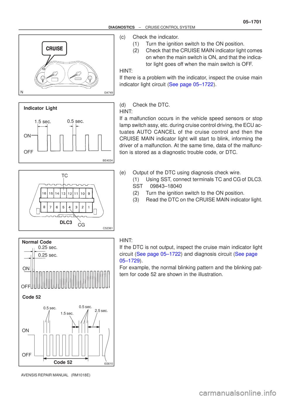
(c)Check the indicator.
(1)Turn the ignition switch to the ON position.
(2)Check that the CRUISE MAIN indicator light comeson when the main switch is ON, and that the indica-
tor light goes off when the main switch is OFF.
HINT:
If there is a problem with the indicator, inspect the cruise main
indicator light circuit (See page 05±1722).
(d)Check the DTC.
HINT:
If a malfunction occurs in the vehicle speed sensors or stop
lamp switch assy, etc. during cruise control driving, the ECU ac-
tuates AUTO CANCEL of the cruise control and then the
CRUISE MAIN indicator light will start to blink, informing the
driver of a malfunction. At the same time, data of the malfunc-
tion is stored as a diagnostic trouble code, or DTC.
(e)Output of the DTC using diagnosis check wire. (1)Using SST, connect terminals TC and CG
of DLC3.
SST09843±18040
(2)Turn the ignition switch to the ON position.
(3)Read the DTC on the CRUISE MAIN indicator light.
HINT:
If the DTC is not output, inspect the cruise main indicator light
circuit (See page 05±1722) and diagnosis circuit (See page
05±1729).
For example, the normal blinking pattern and the blinking pat-
tern for code 52 are shown in the illustration.
Page 1773 of 5135
I35838
(1)
(3)
I35839
(3)
(1)
± DIAGNOSTICSCRUISE CONTROL SYSTEM
05±1703
AVENSIS REPAIR MANUAL (RM1018E)STP LIGHT SW1 S
Stop light SW signal (Sub CPU) /
ON or OFFON : Brake pedal depressed
OFF : Brake pedal released±
SHIFT D POSPNP SW signal (D position) / ON
or OFFON : Shift D position
OFF : Except shift D position±
HINT:
º3º is OK but º1º is NG � ECM failure
º1º is OK but º2º is NG � DTC output or ECM failure
º3º is OK but cruise indicator does not turn on � CRUISE MAIN indicator or wire harness or ECM failure
4. DTC CLEAR
(a) The following methods will erase the DTCs and freeze frame data.
(1) The hand±held tester can be used to erase the codes.
(2) Disconnecting the battery terminals or EFI No.1 fuse can also erase the codes (1AZ±FSE).
Disconnecting the battery terminals or EFI the fuse (1CD±FTV).
(b) After completing repairs, the DTC retained in the memory can be cleared by removing the EFI No.1
fuse for 1 minute or more with the ignition switch to the OFF position.
(c) Check that the normal code is displayed after connecting the fuse.
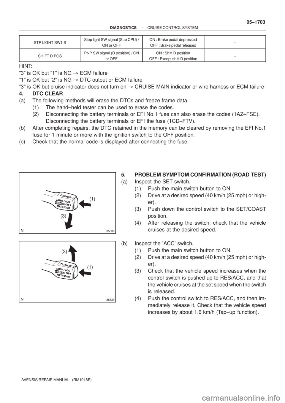
5. PROBLEM SYMPTOM CONFIRMATION (ROAD TEST)
(a) Inspect the SET switch.
(1) Push the main switch button to ON.
(2) Drive at a desired speed (40 km/h (25 mph) or high-
er).
(3) Push down the control switch to the SET/COAST
position.
(4) After releasing the switch, check that the vehicle
cruises at the desired speed.
(b) Inspect the 'ACC' switch.
(1) Push the main switch button to ON.
(2) Drive at a desired speed (40 km/h (25 mph) or high-
er).
(3) Check that the vehicle speed increases when the
control switch is pushed up to RES/ACC, and that
the vehicle cruises at the set speed when the switch
is released.
(4) Push the control switch to RES/ACC, and then im-
mediately release it. Check that the vehicle speed
increases by about 1.6 km/h (Tap±up function).
Page 1775 of 5135
05ADJ±04
CRUISE CONTROL SYSTEM Check Sheet
Inspector 's name:
Customer 's Name
Date of VehicleVIN
Production Date
Licence No.
Odometer Reading / /km
Mile
Condition of
Problem Occurrence
Date of Problem
Frequency
Occurrence
Problem Occurs?
Vehicle Speed when
Problem Occurred / /
� Continuous � Intermittent ( Times a day)
km
Mile Brought in
� Auto cancel
occurs� Driving condition
� City driving � Freeway � Up hill � Down hill
� After cancel occurred, did the driver activate cruise control
again?
� Yes � No
� Cancel does not
occur� With brake ON
� Clutch pedal depressed (M/T)
� Except D range shift (A/T)
� When control SW turns to CANCEL position
� Cruise control
malfunction� Slip to acceleration side
� Slip to deceleration side
� Hunting occurs
� O/D cut off does not occur (A/T)
� O/D does not return (A/T)
� Switch
malfunction� SET � 'ACCEL' � 'COAST' � RESUME � CANCEL
� Remains ON � Does not light up � Blinks Symptoms
DTC Check1st Time2nd Time
� Normal Code � Malfunction Code (Code )
� Normal Code � Malfunction Code (Code ) � CRUISE MAIN
indicator light
± DIAGNOSTICSCRUISE CONTROL SYSTEM
05±1699
AVENSIS REPAIR MANUAL (RM1018E)
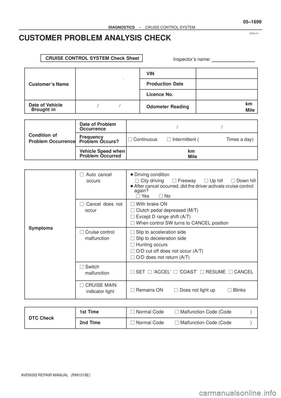
CUSTOMER PROBLEM ANALYSIS CHECK
Page 1776 of 5135
05ADI±04
±
DIAGNOSTICS CRUISE CONTROL SYSTEM
05±1697
AVENSIS REPAIR MANUAL (RM1018E)
CRUISE CONTROL SYSTEM
HOW TO PROCEED WITH TROUBLESHOOTING
1 VEHICLE BROUGHT TO WORK SHOP
2CUSTOMER PROBLEM ANALYSIS (See page 05±1699)
3CHECK AND CLEAR DTCS (See page 05±1700)
4 PROBLEM SYMPTOM CONFIRMATION
SYMPTOM DOES NOT OCCUR (GO TO STEP 5)
SYMPTOM OCCURS (GO TO STEP 6)
5SYMPTOM SIMULATION (See page 01±22)
6DTC CHECK (See page 05±1700)
MALFUNCTION CODE (GO TO STEP 7)
NORMAL CODE (GO TO STEP 8)
7DTC CHART (See page 05±1705)
GO TO STEP 9
8PROBLEM SYMPTOMS TABLE (See page 05±1709)
9CIRCUIT INSPECTION (See page 05±453)
Page 1861 of 5135
100FR±01
A79186
±
ENGINE CONTROL SYSTEM ECM
10±65
AVENSIS REPAIR MANUAL (RM1018E)
ECM
REPLACEMENT
HINT:
1CD±FTV Engine Type:
Each injector assembly has a characteristic fuel injecting behavior. The ECM stores compensation codes
which are used to optimize fuel injection for the injectors. When replacing t\
he ECM, the compensation codes
must be set to the new ECM.
1.REMOVE GLOVE COMPARTMENT DOOR ASSY (See page 71±11)
2.REMOVE ECM
(a)Disconnect the 4 ECM connectors (1ZZ±FE, 3ZZ±FE,1AZ±FE, 1CD±FTV).
(b)Disconnect the 5 ECM connectors (1AZ±FSE).
(c)Disconnect the wire harness clamp.
(d)Remove the bolt and screw, then remove the ECM.
(e)Remove the 2 screws and the ECM bracket No. 1 from the ECM.
(f)Remove the 2 screws and the ECM bracket No. 2 from the ECM.
3.INSTALL ECM Torque: 5.5 N �m (56 kgf �cm, 49 in. �lbf)
4.INSTALL GLOVE COMPARTMENT DOOR ASSY (See page 71±11)
5.REGISTRATION OF INJECTOR COMPENSATION CODE (1CD±FTV ENGINE TYPE) (See page 05±528)
Page 1920 of 5135
110U8±01
A79143
SST
11±60
±
FUEL INJECTOR ASSY(1CD±FTV)
AVENSIS REPAIR MANUAL (RM1018E)
REPLACEMENT
HINT:
Each injector assembly has a characteristic fuel injecting behavior. The ECM stores compensation codes
which are used to optimize fuel injection for the injectors. When replacing t\
he injector assembly, a compensa-
tion code for the new injector assembly must be set to the ECM.
1.REMOVE VACUUM RESERVOIR SUB±ASSY
(a)Disconnect the 2 vacuum hoses and the connector.
(b)Remove the 2 bolts and the vacuum reservoir.
2.REMOVE RADIATOR SUPPORT OPENING COVER
3.REMOVE ENGINE COVER NO.1
(a)Remove the 5 nuts and the engine cover.
4.REMOVE AIR CLEANER ASSY
(a)Disconnect the connector.
(b)Remove the air cleaner cap with the air cleaner hose.
(c)Remove the air cleaner filter element.
(d)Remove the 3 bolts and the air cleaner case.
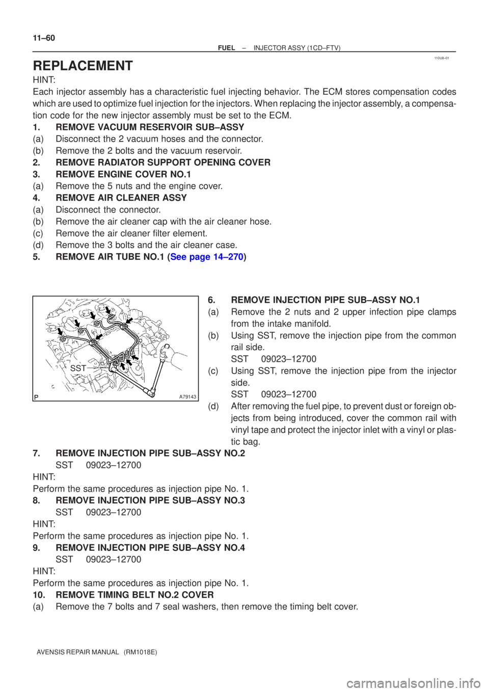
5.REMOVE AIR TUBE NO.1 (See page 14±270) 6. REMOVE INJECTION PIPE SUB±ASSY NO.1
(a) Remove the 2 nuts and 2 upper infection pipe clampsfrom the intake manifold.
(b) Using SST, remove the injection pipe from the common rail side.
SST 09023±12700
(c) Using SST, remove the injection pipe from the injector side.
SST 09023±12700
(d) After removing the fuel pipe, to prevent dust or foreign ob- jects from being introduced, cover the common rail with
vinyl tape and protect the injector inlet with a vinyl or plas-
tic bag.
7. REMOVE INJECTION PIPE SUB±ASSY NO.2
SST 09023±12700
HINT:
Perform the same procedures as injection pipe No. 1.
8. REMOVE INJECTION PIPE SUB±ASSY NO.3 SST 09023±12700
HINT:
Perform the same procedures as injection pipe No. 1.
9. REMOVE INJECTION PIPE SUB±ASSY NO.4 SST 09023±12700
HINT:
Perform the same procedures as injection pipe No. 1.
10. REMOVE TIMING BELT NO.2 COVER
(a) Remove the 7 bolts and 7 seal washers, then remove the timing belt cover\
.