Page 1656 of 5135

05AEY±02
05±1586
±
DIAGNOSTICS KEY REMINDER WARNING SYSTEM
AVENSIS REPAIR MANUAL (RM1018E)
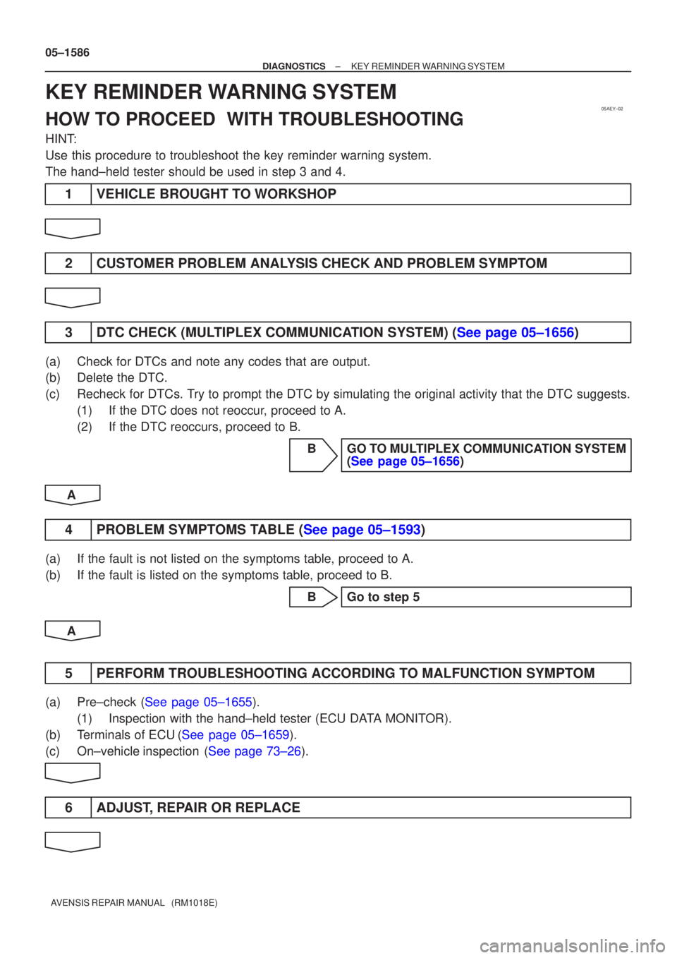
KEY REMINDER WARNING SYSTEM
HOW TO PROCEED WITH TROUBLESHOOTING
HINT:
Use this procedure to troubleshoot the key reminder warning system.
The hand±held tester should be used in step 3 and 4.
1 VEHICLE BROUGHT TO WORKSHOP
2 CUSTOMER PROBLEM ANALYSIS CHECK AND PROBLEM SYMPTOM
3DTC CHECK (MULTIPLEX COMMUNICATION SYSTEM) (See page 05±1656)
(a) Check for DTCs and note any codes that are output.
(b) Delete the DTC.
(c) Recheck for DTCs. Try to prompt the DTC by simulating the original activity that the DTC su\
ggests. (1) If the DTC does not reoccur, proceed to A.
(2) If the DTC reoccurs, proceed to B.
B GO TO MULTIPLEX COMMUNICATION SYSTEM(See page 05±1656)
A
4PROBLEM SYMPTOMS TABLE (See page 05±1593)
(a) If the fault is not listed on the symptoms table, proceed to A.
(b) If the fault is listed on the symptoms table, proceed to B. B Go to step 5
A
5 PERFORM TROUBLESHOOTING ACCORDING TO MALFUNCTION SYMPTOM
(a)Pre±check (See page 05±1655). (1) Inspection with the hand±held tester (ECU DATA MONITOR).
(b)Terminals of ECU(See page 05±1659).
(c)On±vehicleinspection (See page 73±26).
6 ADJUST, REPAIR OR REPLACE
Page 1674 of 5135

05BA6±01
±
DIAGNOSTICS THEFT DETERRENT SYSTEM
05±1627
AVENSIS REPAIR MANUAL (RM1018E)
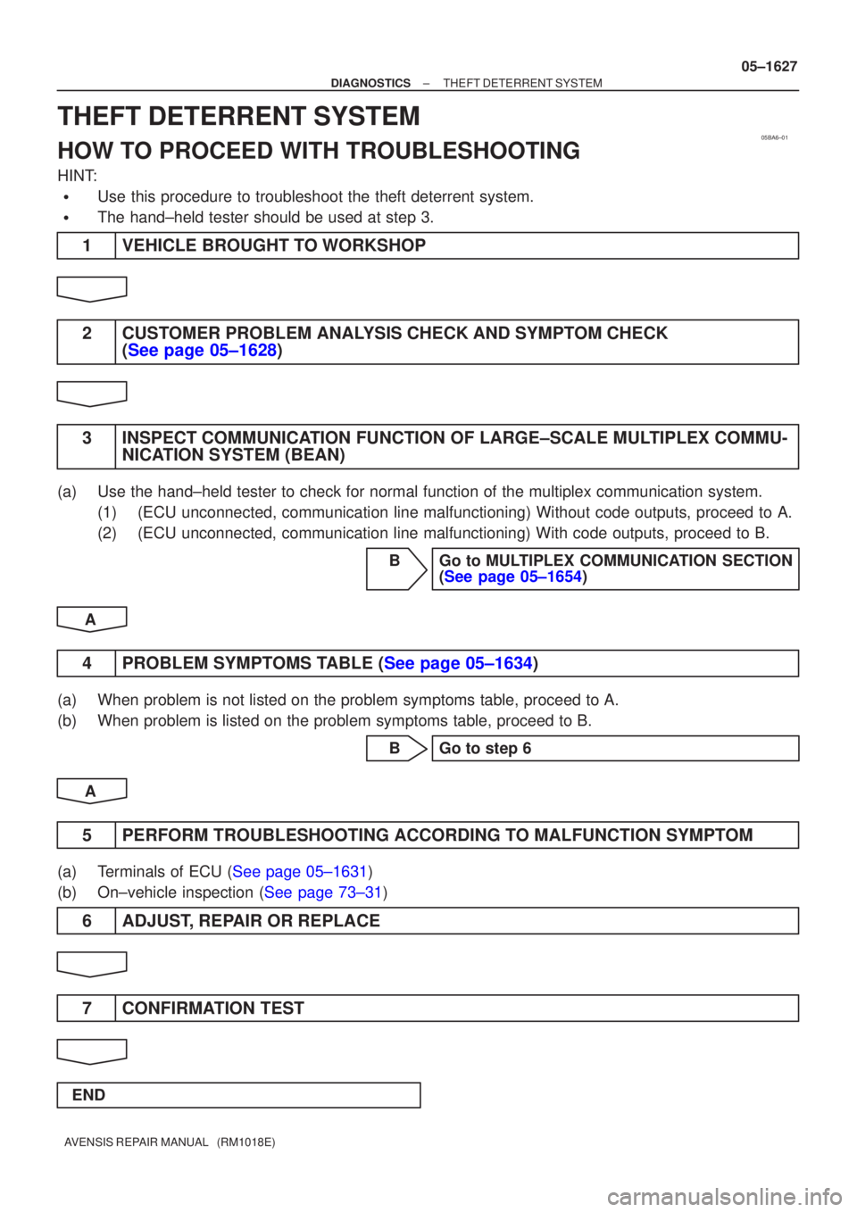
THEFT DETERRENT SYSTEM
HOW TO PROCEED WITH TROUBLESHOOTING
HINT:
�Use this procedure to troubleshoot the theft deterrent system.
�The hand±held tester should be used at step 3.
1VEHICLE BROUGHT TO WORKSHOP
2CUSTOMER PROBLEM ANALYSIS CHECK AND SYMPTOM CHECK
(See page 05±1628)
3INSPECT COMMUNICATION FUNCTION OF LARGE±SCALE MULTIPLEX COMMU- NICATION SYSTEM (BEAN)
(a)Use the hand±held tester to check for normal function of the multiple\
x communication system.
(1)(ECU unconnected, communication line malfunctioning) Without code outp\
uts, proceed to A.
(2)(ECU unconnected, communication line malfunctioning) With code outputs\
, proceed to B.
BGo to MULTIPLEX COMMUNICATION SECTION(See page 05±1654)
A
4PROBLEM SYMPTOMS TABLE (See page 05±1634)
(a)When problem is not listed on the problem symptoms table, proceed to A.
(b)When problem is listed on the problem symptoms table, proceed to B. BGo to step 6
A
5PERFORM TROUBLESHOOTING ACCORDING TO MALFUNCTION SYMPTOM
(a)Terminals of ECU (See page 05±1631)
(b)On±vehicle inspection (See page 73±31)
6 ADJUST, REPAIR OR REPLACE
7 CONFIRMATION TEST
END
Page 1675 of 5135

B66227
E10
ECMT8
Transponder Key ECU Assy
IMI
IMO30*
1
27*2
29*1
26*2W GR
6
7EFIO
EFII
*1: 1CD±FTV
*2: Gasoline
± DIAGNOSTICSENGINE IMMOBILISER SYSTEM
05±1625
AVENSIS REPAIR MANUAL (RM1018E)
DTC B2799 ENGINE IMMOBILISER SYSTEM
MALFUNCTION
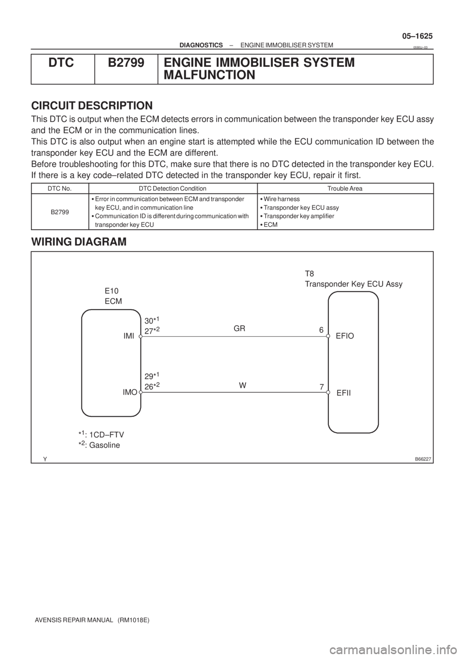
CIRCUIT DESCRIPTION
This DTC is output when the ECM detects errors in communication between the transponder key ECU assy
and the ECM or in the communication lines.
This DTC is also output when an engine start is attempted while the ECU communication ID between the
transponder key ECU and the ECM are different.
Before troubleshooting for this DTC, make sure that there is no DTC detected in the transponder key ECU.
If there is a key code±related DTC detected in the transponder key ECU, repair it first.
DTC No.DTC Detection ConditionTrouble Area
B2799
�Error in communication between ECM and transponder
key ECU, and in communication line
�Communication ID is different during communication with
transponder key ECU�Wire harness
�Transponder key ECU assy
�Transponder key amplifier
�ECM
WIRING DIAGRAM
05B0J±03
Page 1677 of 5135
B52550
I12
Transponder Key AmplifierT8
Transponder Key ECU Assy
Y±G
CODE
411CODE
05±1624
± DIAGNOSTICSENGINE IMMOBILISER SYSTEM
AVENSIS REPAIR MANUAL (RM1018E)
DTC B2797 COMMUNICATION MALFUNCTION NO.1
CIRCUIT DESCRIPTION
This DTC is output when an error occurs in normal communication.
HINT:
Some noise is found in the communication line.
DTC No.DTC Detection ConditionTrouble Area
B2797Keys are positioned too close to each other or noise oc-
curred in communication line
�Key
�Wire harness
�Transponder key amplifier
�Transponder key ECU assy
WIRING DIAGRAM
INSPECTION PROCEDURE
1 CHECK OPERATION OF TRANSPONDER KEY AMPLIFIER
(a) After replacing the transponder key amplifier, check that the engine starts.
OK NORMAL
(TRANSPONDER KEY AMPLIFIER DEFECTIVE)
NG
REPLACE TRANSPONDER KEY ECU ASSY
05B0I±03
Page 1678 of 5135
B62676
I12
Transponder Key AmplifierT8
Transponder Key ECU Assy
VC5
CODE
TXCT
AGND Y±B
Y±G
L±R
GR±R8
11
12
13 1
4
5
7 TXCT
GND
ANT2 ANT1 VC5
CODE
CoilAmplifier
± DIAGNOSTICSENGINE IMMOBILISER SYSTEM
05±1621
AVENSIS REPAIR MANUAL (RM1018E)
DTC B2796 NO COMMUNICATION IN IMMOBILISER
SYSTEM
DTC B2798 COMMUNICATION MALFUNCTION NO.2
CIRCUIT DESCRIPTION
This code is stored in the memory when a key that does not have a transponder chip is inserted or if commu-
nication between the key and transponder key ECU is impossible.
DTC No.DTC Detection ConditionTrouble Area
B2796No communication
�Key
�Wire harness
�Transponder key amplifier (Transponder key coil)
�Transponder key ECU assy
B2798Communication error�Key
WIRING DIAGRAM
05B0H±03
Page 1680 of 5135

������
��� ����
������B64974
I12
Transponder Key Amplifier Wire Harness Side
T8
Transponder Key ECU Assy
± DIAGNOSTICSENGINE IMMOBILISER SYSTEM
05±1623
AVENSIS REPAIR MANUAL (RM1018E)
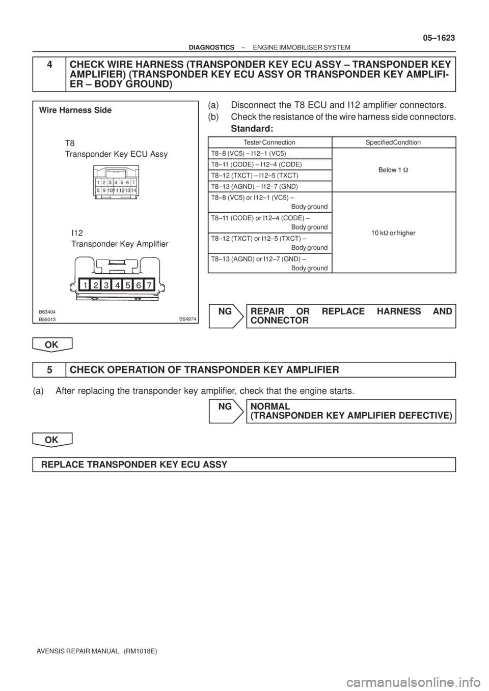
4 CHECK WIRE HARNESS (TRANSPONDER KEY ECU ASSY ± TRANSPONDER KEY
AMPLIFIER) (TRANSPONDER KEY ECU ASSY OR TRANSPONDER KEY AMPLIFI-
ER ± BODY GROUND)
(a) Disconnect the T8 ECU and I12 amplifier connectors.
(b) Check the resistance of the wire harness side connectors.
Standard:
Tester ConnectionSpecified Condition
T8±8 (VC5) ± I12±1 (VC5)
T8±11 (CODE) ± I12±4 (CODE)Below 1�T8±12 (TXCT) ± I12±5 (TXCT)Below 1 �
T8±13 (AGND) ± I12±7 (GND)
T8±8 (VC5) or I12±1 (VC5) ±
Body ground
T8±11 (CODE) or I12±4 (CODE) ±
Body ground
10 k�or higherT8±12 (TXCT) or I12±5 (TXCT) ±
Body ground10 k� or higher
T8±13 (AGND) or I12±7 (GND) ±
Body ground
NG REPAIR OR REPLACE HARNESS AND
CONNECTOR
OK
5 CHECK OPERATION OF TRANSPONDER KEY AMPLIFIER
(a) After replacing the transponder key amplifier, check that the engine starts.
NG NORMAL
(TRANSPONDER KEY AMPLIFIER DEFECTIVE)
OK
REPLACE TRANSPONDER KEY ECU ASSY
Page 1681 of 5135
05±1620
± DIAGNOSTICSENGINE IMMOBILISER SYSTEM
AVENSIS REPAIR MANUAL (RM1018E)
DTC B2795 UNMATCHED KEY CODE
CIRCUIT DESCRIPTION
This DTC is output when a key with a key code that has not been registered in the ECU is inserted into the
ignition key cylinder.
DTC No.DTC Detection ConditionTrouble Area
B2795Key with unregistered key code is inserted�Key
INSPECTION PROCEDURE
1 DELETE DTC AND INSERT ALL PRESENTLY AVAILABLE KEYS TO CHECK
WHETHER ENGINE STARTS OR NOT
OK NO PROBLEM
(BECAUSE OF KEY RE±REGISTRATION)
NG
REPLACE KEY THAT WILL NOT START ENGINE
05B0G±03
Page 1682 of 5135
± DIAGNOSTICSENGINE IMMOBILISER SYSTEM
05±1619
AVENSIS REPAIR MANUAL (RM1018E)
DTC B2794 UNMATCHED ENCRYPTION CODE
CIRCUIT DESCRIPTION
This DTC is output when a key with an incomplete key code is inserted into the ignition key cylinder.
DTC No.DTC Detection ConditionTrouble Area
B2794Key with incomplete key code is inserted�Key
INSPECTION PROCEDURE
1 REPLACE KEY
05B0F±03