Page 1387 of 5135

C
D
E
F
05±1356
±
DIAGNOSTICS SUPPLEMENTAL RESTRAINT SYSTEM
AVENSIS REPAIR MANUAL")
�����
����� �\b���H42142
Airbag
Sensor
Assy
CenterSpiral
Cable
Sub±assy
DLC3
CG TC DTC B1182/19
D Squib
(2nd step)
C
D
E
F
05±1356
±
DIAGNOSTICS SUPPLEMENTAL RESTRAINT SYSTEM
AVENSIS REPAIR MANUAL (RM1018E)
3CHECK HORN BUTTON ASSY(D SQUIB, 2ND STEP)
(a)Turn the ignition switch to the LOCK position.
(b)Disconnect the negative (±) terminal cable from the bat- tery, and wait for at least 90 seconds.
(c)Connect the connectors to the horn button assy.
(d)Connect the negative (±) terminal cable to the battery, and wait for at least 2 seconds.
(e)Turn the ignition switch to the ON position, and wait for at
least 10 seconds.
(f)Clear the stored DTCs in the memory (See page 05±1184).
(g) Turn the ignition switch to the LOCK position.
(h) Turn the ignition switch to the ON position, and wait for at
least 10 seconds.
(i)Check the DTCs (See page 05±1184). OK:
DTC B1182/19 is not output.
HINT:
Codes other than code B1182/19 may be output at this time, but
they are not related to this check.
NG REPLACE HORN BUTTON ASSY
OK
4 USE SIMULATION METHOD TO CHECK
NG Go to step 1
OK
REPLACE ALL SRS COMPONENTS INCLUDING WIRE HARNESS
Page 1389 of 5135

Airbag
Sensor
Assy
Center
Spiral
Cable
Sub±assy
Color: Black
A
B
C
D
E
F
05±1350
±
DIAGNOSTICS SUPPLEMENTAL RESTRAINT SYSTEM
AVENSIS REPAIR MANUAL")
\b�����������
���
���
H41475
D Squib
(2nd step)
Airbag
Sensor
Assy
Center
Spiral
Cable
Sub±assy
Color: Black
A
B
C
D
E
F
05±1350
±
DIAGNOSTICS SUPPLEMENTAL RESTRAINT SYSTEM
AVENSIS REPAIR MANUAL (RM1018E)
DTC B1181/18 OPEN IN D SQUIB (2ND STEP) CIRCUIT
CIRCUIT DESCRIPTION
The D squib (2nd step) circuit consists of the airbag sensor assy center, the spiral cable sub±assy and the
horn button assy.
This circuit actuates the SRS to deploy when the SRS deployment conditio\
ns are fulfilled.
DTC B1181/18 is recorded when an open circuit is detected in the D squib (2nd\
step) circuit.
DTC No.DTC Detecting ConditionTrouble Area
B1181/18
� Open circuit in D2+ wire harness or D2± wire harness of D
squib (2nd step)
� D squib (2nd step) malfunction
� Spiral cable sub±assy malfunction
� Airbag sensor assy center malfunction�Horn button assy (D squib, 2nd step)
� Spiral cable sub±assy
� Airbag sensor assy center
� Instrument panel wire
WIRING DIAGRAM
See page 05±1346.
INSPECTION PROCEDURE
1 CHECK D SQUIB CIRCUIT(2ND STEP)
(a) Turn the ignition switch to the LOCK position.
(b) Disconnect the negative (±) terminal cable from the bat-
tery, and wait for at least 90 seconds.
(c) Disconnect the connectors from the airbag sensor assy center and the horn button assy.
(d) Measure the resistance between D2+ and D2± of the con- nector ºEº.
OK:
Resistance: Below 1 �
NG Go to step 4
OK
056MR±03
Page 1391 of 5135

C
D
E
F
���
���
������
������H41478
Airbag
Sensor
Assy
CenterSpiral
Cable
Sub±assy")
������������
\b ���H42140
Airbag
Sensor
Assy
CenterSpiral
Cable
Sub±assy
DLC3
CG TC DTC B1181/18
D Squib
(2nd step)
C
D
E
F
���
���
������
������H41478
Airbag
Sensor
Assy
CenterSpiral
Cable
Sub±assy
Instrument Panel Wire
D Squib
(2nd step) C
D
E
FB A
05±1352
±
DIAGNOSTICS SUPPLEMENTAL RESTRAINT SYSTEM
AVENSIS REPAIR MANUAL (RM1018E)
3CHECK HORN BUTTON ASSY(D SQUIB, 2ND STEP)
(a)Turn the ignition switch to the LOCK position.
(b)Disconnect the negative (±) terminal cable from the bat- tery, and wait for at least 90 seconds.
(c)Connect the connectors to the horn button assy.
(d)Connect the negative (±) terminal cable to the battery, and wait for at least 2 seconds.
(e)Turn the ignition switch to the ON position, and wait for at
least 10 seconds.
(f)Clear the stored DTCs in the memory (See page 05±1184).
(g) Turn the ignition switch to the LOCK position.
(h) Turn the ignition switch to the ON position, and wait for at
least 10 seconds.
(i)Check the DTCs (See page 05±1184). OK:
DTC B1181/18 is not output.
HINT:
Codes other than code B1181/18 may be output at this time, but
they are not related to this check.
NG REPLACE HORN BUTTON ASSY
OK
USE SIMULATION METHOD TO CHECK
4 CHECK INSTRUMENT PANEL WIRE
(a) Disconnect the instrument panel wire connector from the spiral cable sub±assy.
(b) Measure the resistance between D2+ and D2± of the con- nector ºCº.
OK:
Resistance: Below 1 �
NG REPAIR OR REPLACE INSTRUMENT PANEL WIRE
OK
Page 1393 of 5135
H01451
Airbag Sensor Assy Center
A30
D Squib (2nd step)
Spiral Cable
Sub±assyY±R Y±G
D2+
D2± 4A27
3A271716 05±1346
± DIAGNOSTICSSUPPLEMENTAL RESTRAINT SYSTEM
AVENSIS REPAIR MANUAL (RM1018E)
DTC B1180/17 SHORT IN D SQUIB (2ND STEP) CIRCUIT
CIRCUIT DESCRIPTION
The D squib (2nd step) circuit consists of the airbag sensor assy center, the spiral cable sub±assy and the
horn button assy.
This circuit actuates the SRS to deploy when the SRS deployment conditions are fulfilled.
DTC B1180/17 is recorded when a short circuit is detected in the D squib (2nd step) circuit.
DTC No.DTC Detecting ConditionTrouble Area
B1180/17
�Short circuit between D2+ wire harness and D2± wire har-
ness of D squib (2nd step)
�D squib (2nd step) malfunction
�Spiral cable sub±assy malfunction
�Airbag sensor assy center malfunction�Horn button assy (D squib, 2nd step)
�Spiral cable sub±assy
�Airbag sensor assy center
�Instrument panel wire
WIRING DIAGRAM
056MQ±03
Page 1394 of 5135
\b�����������
���
���
H41475
D Squib
(2nd step)
Airbag
Sensor
Assy
Center
Spiral
Cable
Sub±assy
Color: Black
A
B
C
D
E
F
±
DIAGNOSTICS SUPPLEMENTAL RESTRAINT SYSTEM
05±1347
AVENSIS REPAIR MANUAL (RM1018E)
INSPECTION PROCEDURE
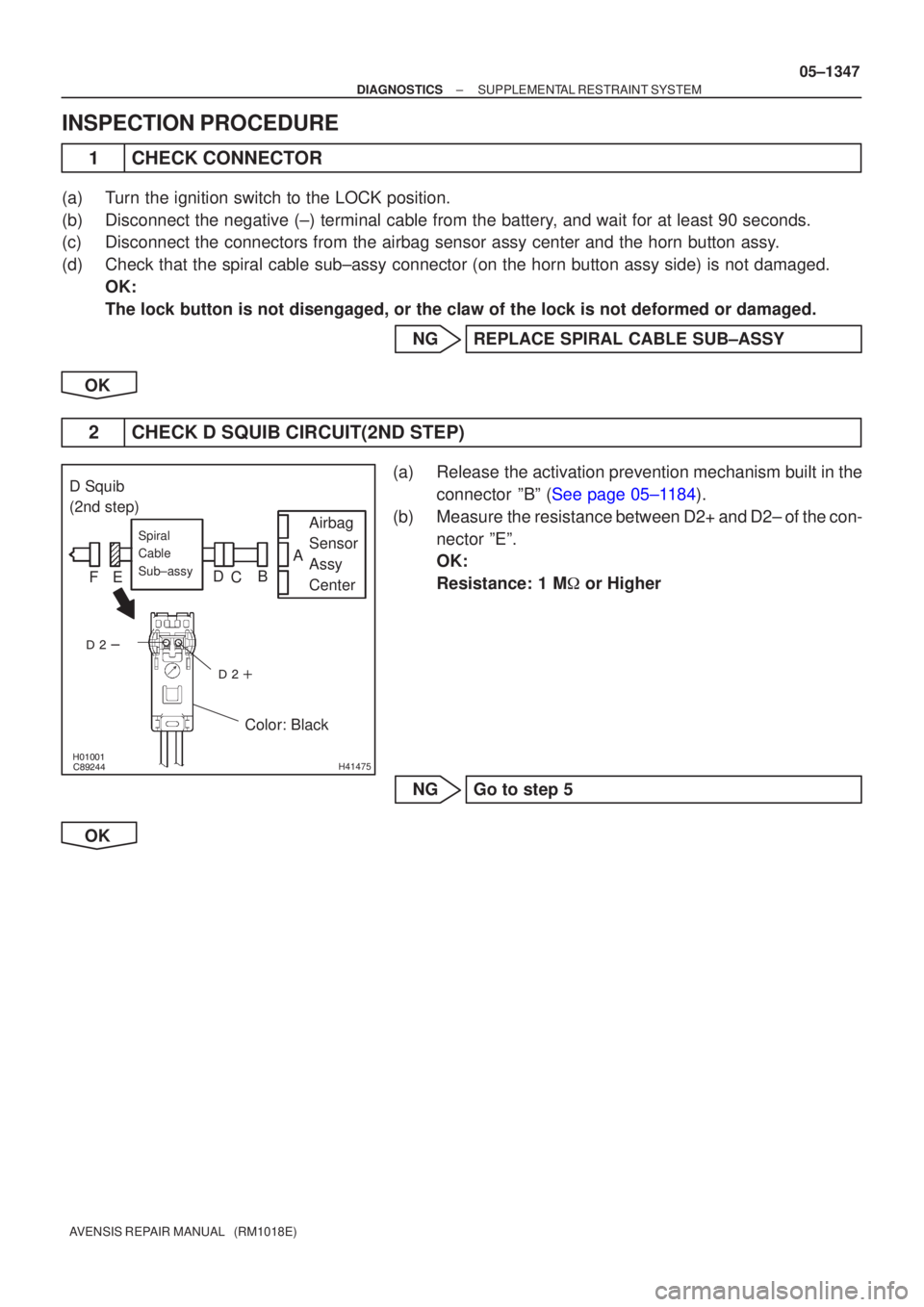
1CHECK CONNECTOR
(a)Turn the ignition switch to the LOCK position.
(b)Disconnect the negative (±) terminal cable from the battery, and wait for at least 90 seconds.
(c)Disconnect the connectors from the airbag sensor assy center and the hor\
n button assy.
(d)Check that the spiral cable sub±assy connector (on the horn button a\
ssy side) is not damaged.
OK:
The lock button is not disengaged, or the claw of the lock is not deform\
ed or damaged.
NGREPLACE SPIRAL CABLE SUB±ASSY
OK
2CHECK D SQUIB CIRCUIT(2ND STEP)
(a)Release the activation prevention mechanism built in the connector ºBº (See page 05±1184).
(b) Measure the resistance between D2+ and D2± of the con- nector ºEº.
OK:
Resistance: 1 M � or Higher
NG Go to step 5
OK
Page 1395 of 5135

C
D
E
F
�����
����� �\b���H42138
Airbag
Sensor
Assy
CenterSpiral
Cable
Sub±assy")
�����
����� �\b���H42137
Airbag
Sensor
Assy
CenterSpiral
Cable
Sub±assy
DLC3
CG TC DTC B1180/17
D Squib
(2nd step)
C
D
E
F
�����
����� �\b���H42138
Airbag
Sensor
Assy
CenterSpiral
Cable
Sub±assy
DLC3
CG TC DTC B1180/17
D Squib
(2nd step)
C
D
E
F
05±1348
±
DIAGNOSTICS SUPPLEMENTAL RESTRAINT SYSTEM
AVENSIS REPAIR MANUAL (RM1018E)
3CHECK AIR BAG SENSOR ASSY CENTER
(a)Connect the connector to the airbag sensor assy center.
(b)Connect the negative (±) terminal cable to the battery, and wait for at least 2 seconds.
(c)Turn the ignition switch to the ON position, and wait for at least 10 seconds.
(d)Clear the stored DTCs in the memory (See page 05±1184).
(e)Turn the ignition switch to the LOCK position.
(f)Turn the ignition switch to the ON position, and wait for at least 10 seconds.
(g)Check the DTCs (See page 05±1184).
OK:
DTC B1180/17 is not output.
HINT:
Codes other than code B1180/17 may be output at this time, but
they are not related to this check.
NGREPLACE AIR BAG SENSOR ASSY CENTER
OK
4CHECK HORN BUTTON ASSY(D SQUIB, 2ND STEP)
(a)Turn the ignition switch to the LOCK position.
(b)Disconnect the negative (±) terminal cable from the bat- tery, and wait for at least 90 seconds.
(c)Connect the connectors to the horn button assy.
(d)Connect the negative (±) terminal cable to the battery, and wait for at least 2 seconds.
(e)Turn the ignition switch to the ON position, and wait for at
least 10 seconds.
(f)Clear the stored DTCs in the memory (See page 05±1184).
(g) Turn the ignition switch to the LOCK position.
(h) Turn the ignition switch to the ON position, and wait for at least 10 seconds.
(i)Check the DTCs (See page 05±1184). OK:
DTC B1180/17 is not output.
HINT:
Codes other than code B1180/17 may be output at this time, but
they are not related to this check.
NG REPLACE HORN BUTTON ASSY
OK
USE SIMULATION METHOD TO CHECK
Page 1425 of 5135

2. IDENTIFICATION OF NOISE SOURCE
(a) Identify the condition under which the noise occurs, and
check the noise filter on the relat")
05±1404
± DIAGNOSTICSAUDIO SYSTEM
AVENSIS REPAIR MANUAL (RM1018E)
2. IDENTIFICATION OF NOISE SOURCE
(a) Identify the condition under which the noise occurs, and
check the noise filter on the related part.
Condition in which noise occursNoise Source
Depressing the acceleration pedal increases noise, and stopping the engine
erases the noise immediately.Generator
Noise occurs during the A/C or the heater operation.Blower motor
Rapid acceleration while driving on the unpaved road or after the IG switch is
turned ON makes noise.Fuel pump
Pressing and then releasing the horn switch, and keeping pressing the horn
switch makes unusual noise.Horn
Stopping the engine erases small noise that has been heard.Ignition
Noise occurs synchronously with the turn signal flash.Flasher
Noise occurs during the window washer operation.Washer
Noise occurs during the engine running, and it continues after the engine
stops.Engine coolant temperature sensor
Noise occurs during the wiper operation.Wiper
Noise occurs when the brake pedal is depressed.Stop light switch
Others.Static electricity stored on the vehicle
(b) Reference:
�Make sure first that there is no noise from outside.
Failing to do so makes the noise source detection
difficult and leads to misunderstanding.
�The noise should be removed in descending order
of loudness.
�Setting the radio untuned makes noise noticeable,
making the recognition of the phenomenon easier.
Page 1475 of 5135

NOISE OCCURS
INSPECTION PROCEDURE
1 CHECK OF SPEAKER INSTALLATION
(a) Check the speaker installation condition.
(1) Check that eac")
± DIAGNOSTICSAUDIO SYSTEM
05±1419
AVENSIS REPAIR MANUAL (RM1018E)
NOISE OCCURS
INSPECTION PROCEDURE
1 CHECK OF SPEAKER INSTALLATION
(a) Check the speaker installation condition.
(1) Check that each speaker is securely installed.
Standard: Malfunction disappears.
HINT:
The radio is equipped with the noise prevention system that works against only the excessively large noise,
thereby excessively large noise do not occur in the radio. If large noise occurs, check whether or not the earth
on the antenna installation part and the proper noise±prevention equipment are all installed, and whether
or not the improper wiring is held.
Condition in which noise occursNoise type
Depressing the acceleration pedal increases noise, and stopping the engine
erases the noise immediately.Alternator noise
Noise occurs during the A/C or the heater operation.Blower motor noise
Rapid acceleration during the drive on the unpaved road or after the IG
switch is turned ON makes noise.Fuel pump noise
Pressing and then releasing the horn switch, and keeping pressing the horn
switch makes noise.Horn noise
Stopping the engine erases the small noise that has been heard.Ignition noise
Noise occurs in turn with the blink of the turn signal flash.Flasher noise
Noise occurs during the window washer operation.Washer noise
Noise occurs during the engine running, and it continues to occur after the
engine is stopped.Water temperature sensor noise
Noise occurs during the wiper operation.Wiper noise
Noise occurs when the brake pedal is depressed.Stop light switch noise
Others.Static electricity on the vehicle
HINT:
�Identify the condition under which the noise occurs, and check the noise filter on the related part.
�Make sure first that there is no noise from outside. Failing to do so makes the noise occurrence source
detection impossible and leads to misunderstanding.
�The noise should be removed in descending order of loudness.
NG INSTALL IT PROPERLY
OK
IDENTIFICATION OF NOISE SOURCE
054A1±09

Spiral Cable
Sub±assyY±R Y±G
D2+
D2± 4A27
3A271716 05±1346
± DIAGNOSTICSSUPPLEMENTAL RESTRAINT SYSTEM
AVENSIS REPAIR MANUAL (RM1018E)")