Page 1237 of 5135
H42671
Side Airbag
Sensor Assy RH
Airbag Front
RH Sensor
Airbag Sensor
Assy Center
Airbag Sensor
Front LH
Side Airbag
Sensor Assy LH
Airbag Sensor
Rear LH (*1)
Seat Position
Airbag Sensor
(*2)Horn Button Assy
(Squib) Instrument Panel
Passenger Airbag
Assy (Squib)Front Seat Outer
Belt Assy RH
(Squib)
Front Seat
Airbag Assy RH
(Squib)
Front Seat
Airbag Assy
LH (Squib)
Curtain Shield
Airbag Assy LH
(Squib) (*1) Airbag Sensor
Rear RH (*1)Curtain Shield
Airbag Assy RH
(Squib) (*1)
Front Seat Outer
Belt Assy LH
(Squib) Seat Position
Airbag Sensor
(*3)
Instrument Panel
Airbag Assy (Squib)
Spiral Cable
Sub±assy 7
15 8
16
513
614 3 11
412
19
210
23
24 2129
2230
1927
2028
17 25
1826
34 5
6
78
11
12 9
1025
26
27
28
29
30
*1: w/ Curtain Shield Airbag
*2: LHD
*3: RHD 05±1188
± DIAGNOSTICSSUPPLEMENTAL RESTRAINT SYSTEM
AVENSIS REPAIR MANUAL (RM1018E)
Page 1277 of 5135
������������
��
��
H41439
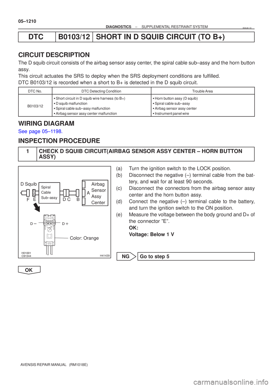
D Squib
Airbag
Sensor
Assy
CenterSpiral
Cable
Sub±assy
Color: Orange
A
B
C
D
E
F
05±1210
±
DIAGNOSTICS SUPPLEMENTAL RESTRAINT SYSTEM
AVENSIS REPAIR MANUAL (RM1018E)
DTCB0103/12SHORT IN D SQUIB CIRCUIT (TO B+)
CIRCUIT DESCRIPTION
The D squib circuit consists of the airbag sensor assy center, the spiral cable sub±assy and the horn button
assy.
This circuit actuates the SRS to deploy when the SRS deployment conditions a\
re fulfilled.
DTC B0103/12 is recorded when a short to B+ is detected in the D squib c\
ircuit.
DTC No.DTC Detecting ConditionTrouble Area
B0103/12
� Short circuit in D squib wire harness (to B+)
� D squib malfunction
� Spiral cable sub±assy malfunction
� Airbag sensor assy center malfunction�Horn button assy (D squib)
� Spiral cable sub±assy
� Airbag sensor assy center
� Instrument panel wire
WIRING DIAGRAM
See page 05±1198.
INSPECTION PROCEDURE
1 CHECK D SQUIB CIRCUIT(AIRBAG SENSOR ASSY CENTER ± HORN BUTTON
ASSY)
(a) Turn the ignition switch to the LOCK position.
(b) Disconnect the negative (±) terminal cable from the bat-
tery, and wait for at least 90 seconds.
(c) Disconnect the connectors from the airbag sensor assy center and the horn button assy.
(d) Connect the negative (±) terminal cable to the battery, and turn the ignition switch to the ON position.
(e) Measure the voltage between the body ground and D+ of the connector ºEº.
OK:
Voltage: Below 1 V
NG Go to step 5
OK
054LM±10
Page 1279 of 5135
������������\b�����H40038
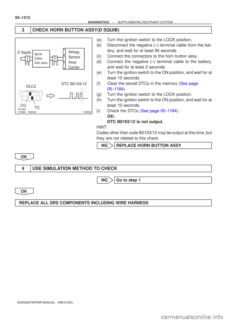
D SquibDLC3 DTC B0103/12
CG
TC Airbag
Sensor
Assy
Center
Spiral
Cable
Sub±assy
C
D
E
F
05±1212
±
DIAGNOSTICS SUPPLEMENTAL RESTRAINT SYSTEM
AVENSIS REPAIR MANUAL (RM1018E)
3CHECK HORN BUTTON ASSY(D SQUIB)
(a)Turn the ignition switch to the LOCK position.
(b)Disconnect the negative (±) terminal cable from the bat- tery, and wait for at least 90 seconds.
(c)Connect the connectors to the horn button assy.
(d)Connect the negative (±) terminal cable to the battery, and wait for at least 2 seconds.
(e)Turn the ignition switch to the ON position, and wait for at
least 10 seconds.
(f)Clear the stored DTCs in the memory (See page 05±1184).
(g) Turn the ignition switch to the LOCK position.
(h) Turn the ignition switch to the ON position, and wait for at
least 10 seconds.
(i)Check the DTCs (See page 05±1184). OK:
DTC B0103/12 is not output.
HINT:
Codes other than code B0103/12 may be output at this time, but
they are not related to this check.
NG REPLACE HORN BUTTON ASSY
OK
4 USE SIMULATION METHOD TO CHECK
NG Go to step 1
OK
REPLACE ALL SRS COMPONENTS INCLUDING WIRE HARNESS
Page 1281 of 5135
������������
��
��
H41439
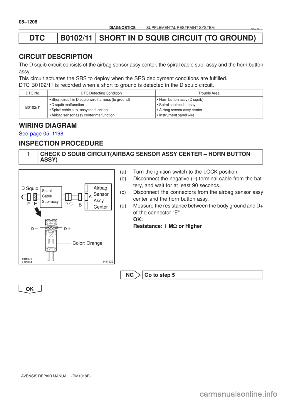
D Squib Airbag
Sensor
Assy
CenterSpiral
Cable
Sub±assy
Color: Orange
A
B
C
D
E
F
05±1206
±
DIAGNOSTICS SUPPLEMENTAL RESTRAINT SYSTEM
AVENSIS REPAIR MANUAL (RM1018E)
DTCB0102/11SHORT IN D SQUIB CIRCUIT (TO GROUND)
CIRCUIT DESCRIPTION
The D squib circuit consists of the airbag sensor assy center, the spiral cable sub±assy and the horn button
assy.
This circuit actuates the SRS to deploy when the SRS deployment conditions a\
re fulfilled.
DTC B0102/11 is recorded when a short to ground is detected in the D squib circuit.\
DTC No.DTC Detecting ConditionTrouble Area
B0102/11
� Short circuit in D squib wire harness (to ground)
� D squib malfunction
� Spiral cable sub±assy malfunction
� Airbag sensor assy center malfunction�Horn button assy (D squib)
� Spiral cable sub±assy
� Airbag sensor assy center
� Instrument panel wire
WIRING DIAGRAM
See page 05±1198.
INSPECTION PROCEDURE
1 CHECK D SQUIB CIRCUIT(AIRBAG SENSOR ASSY CENTER ± HORN BUTTON
ASSY)
(a) Turn the ignition switch to the LOCK position.
(b) Disconnect the negative (±) terminal cable from the bat-
tery, and wait for at least 90 seconds.
(c) Disconnect the connectors from the airbag sensor assy
center and the horn button assy.
(d) Measure the resistance between the body ground and D+ of the connector ºEº.
OK:
Resistance: 1 M � or Higher
NG Go to step 5
OK
054LL±10
Page 1283 of 5135
������������\b�����H40037
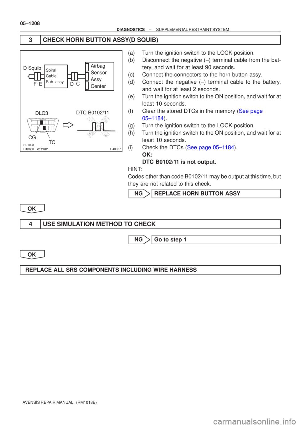
D SquibDLC3 DTC B0102/11
CG
TC Airbag
Sensor
Assy
Center
Spiral
Cable
Sub±assy
FD
E C
05±1208
±
DIAGNOSTICS SUPPLEMENTAL RESTRAINT SYSTEM
AVENSIS REPAIR MANUAL (RM1018E)
3CHECK HORN BUTTON ASSY(D SQUIB)
(a)Turn the ignition switch to the LOCK position.
(b)Disconnect the negative (±) terminal cable from the bat- tery, and wait for at least 90 seconds.
(c)Connect the connectors to the horn button assy.
(d)Connect the negative (±) terminal cable to the battery, and wait for at least 2 seconds.
(e)Turn the ignition switch to the ON position, and wait for at
least 10 seconds.
(f)Clear the stored DTCs in the memory (See page 05±1184).
(g) Turn the ignition switch to the LOCK position.
(h) Turn the ignition switch to the ON position, and wait for at
least 10 seconds.
(i)Check the DTCs (See page 05±1184). OK:
DTC B0102/11 is not output.
HINT:
Codes other than code B0102/11 may be output at this time, but
they are not related to this check.
NG REPLACE HORN BUTTON ASSY
OK
4 USE SIMULATION METHOD TO CHECK
NG Go to step 1
OK
REPLACE ALL SRS COMPONENTS INCLUDING WIRE HARNESS
Page 1381 of 5135
\b�����������
���
���
H41475
D Squib
(2nd step)
Airbag
Sensor
Assy
Center
Spiral
Cable
Sub±assy
Color: Black
A
B
C
D
E
F
05±1358
±
DIAGNOSTICS SUPPLEMENTAL RESTRAINT SYSTEM
AVENSIS REPAIR MANUAL (RM1018E)
DTC B1183/22 SHORT IN D SQUIB (2ND STEP) CIRCUIT (TO B+)
CIRCUIT DESCRIPTION
The D squib (2nd step) circuit consists of the airbag sensor assy center, the spiral cable sub±assy and the
horn button assy.
This circuit actuates the SRS to deploy when the SRS deployment conditio\
ns are fulfilled.
DTC B1183/22 is recorded when a short to B+ is detected in the D squib (2nd s\
tep) circuit.
DTC No.DTC Detecting ConditionTrouble Area
B1183/22
�Short circuit in D squib (2nd step) wire harness (to B+)
� D squib (2nd step) malfunction
� Spiral cable sub±assy malfunction
� Airbag sensor assy center malfunction�Horn button assy (D squib, 2nd step)
� Spiral cable sub±assy
� Airbag sensor assy center
� Instrument panel wire
WIRING DIAGRAM
See page 05±1346.
CIRCUIT INSPECTION
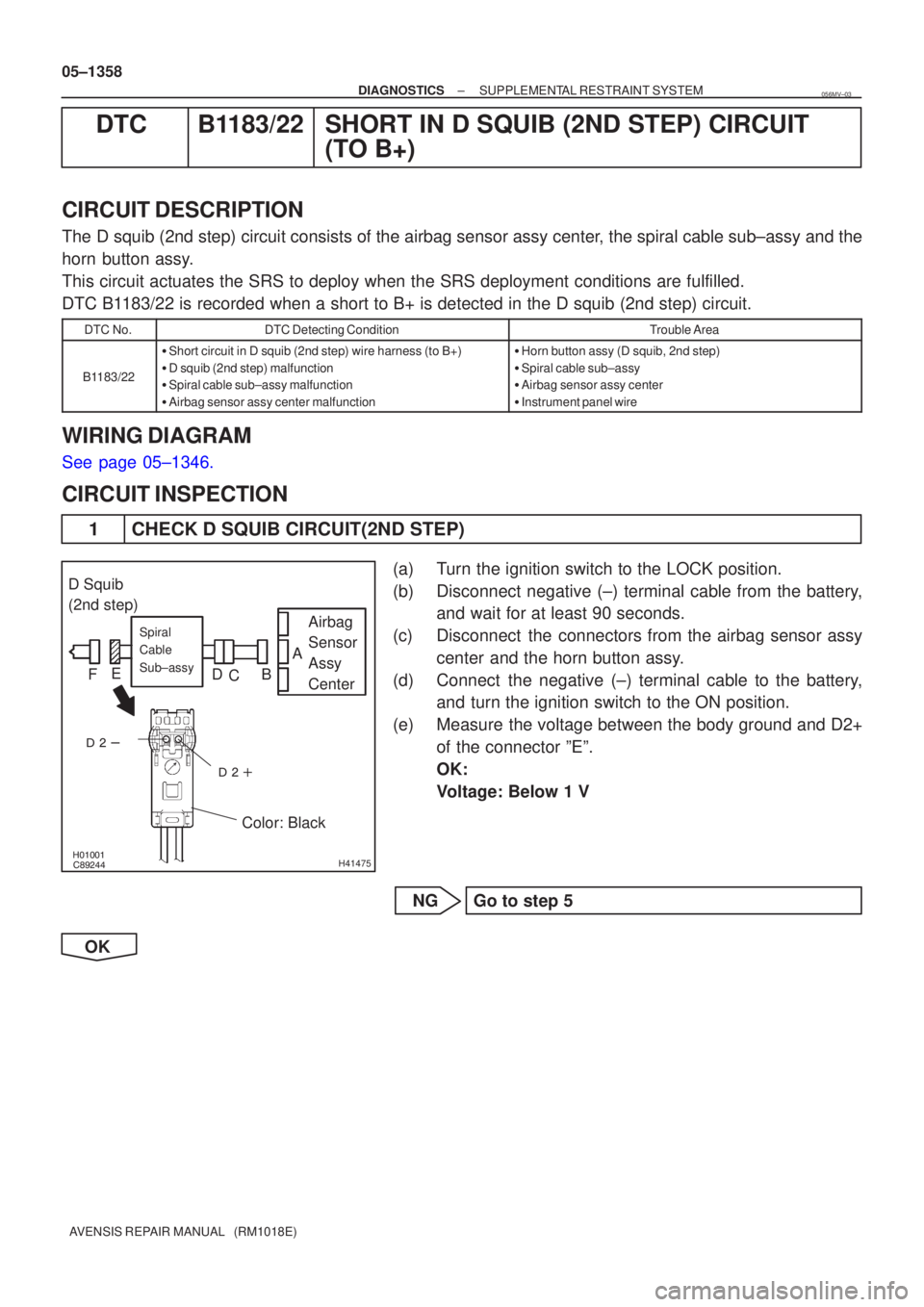
1 CHECK D SQUIB CIRCUIT(2ND STEP)
(a) Turn the ignition switch to the LOCK position.
(b) Disconnect negative (±) terminal cable from the battery,
and wait for at least 90 seconds.
(c) Disconnect the connectors from the airbag sensor assy center and the horn button assy.
(d) Connect the negative (±) terminal cable to the battery, and turn the ignition switch to the ON position.
(e) Measure the voltage between the body ground and D2+ of the connector ºEº.
OK:
Voltage: Below 1 V
NG Go to step 5
OK
056MV±03
Page 1383 of 5135
����� �����\b�����H42144
Airbag
Sensor
Assy
CenterSpiral
Cable
Sub±assy
DLC3
CG TC DTC B1183/22
D Squib
(2nd step)
C
D
E
F
05±1360
±
DIAGNOSTICS SUPPLEMENTAL RESTRAINT SYSTEM
AVENSIS REPAIR MANUAL (RM1018E)
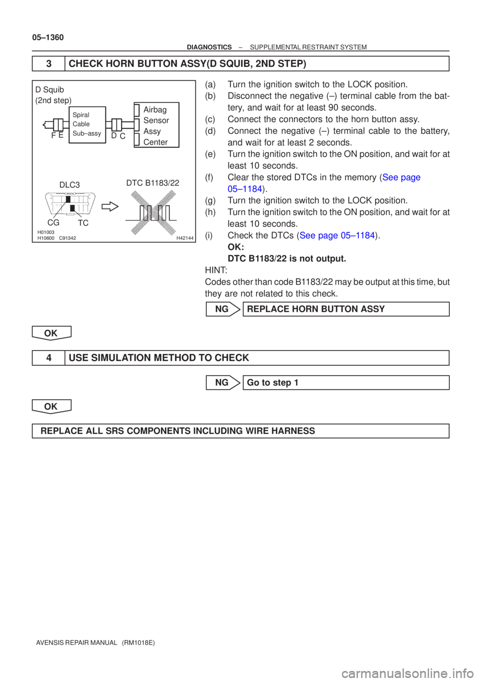
3CHECK HORN BUTTON ASSY(D SQUIB, 2ND STEP)
(a)Turn the ignition switch to the LOCK position.
(b)Disconnect the negative (±) terminal cable from the bat- tery, and wait for at least 90 seconds.
(c)Connect the connectors to the horn button assy.
(d)Connect the negative (±) terminal cable to the battery, and wait for at least 2 seconds.
(e)Turn the ignition switch to the ON position, and wait for at
least 10 seconds.
(f)Clear the stored DTCs in the memory (See page 05±1184).
(g)Turn the ignition switch to the LOCK position.
(h)Turn the ignition switch to the ON position, and wait for at
least 10 seconds.
(i)Check the DTCs (See page 05±1184). OK:
DTC B1183/22 is not output.
HINT:
Codes other than code B1183/22 may be output at this time, but
they are not related to this check.
NG REPLACE HORN BUTTON ASSY
OK
4 USE SIMULATION METHOD TO CHECK
NG Go to step 1
OK
REPLACE ALL SRS COMPONENTS INCLUDING WIRE HARNESS
Page 1385 of 5135
\b�����������
���
���
H41475
D Squib
(2nd step)
Airbag
Sensor
Assy
Center
Spiral
Cable
Sub±assy
Color: Black
A
B
C
D
E
F
05±1354
±
DIAGNOSTICS SUPPLEMENTAL RESTRAINT SYSTEM
AVENSIS REPAIR MANUAL (RM1018E)
DTC B1182/19 SHORT IN D SQUIB (2ND STEP) CIRCUIT (TO GROUND)
CIRCUIT DESCRIPTION
The D squib (2nd step) circuit consists of the airbag sensor assy center, the spiral cable sub±assy and the
horn button assy.
This circuit actuates the SRS to deploy when the SRS deployment conditio\
ns are fulfilled.
DTC B1182/19 is recorded when a short to ground is detected in the D squib (2\
nd step) circuit.
DTC No.DTC Detecting ConditionTrouble Area
B1182/19
�Short circuit in D squib (2nd step) wire harness (to ground)
� D squib (2nd step) malfunction
� Spiral cable sub±assy malfunction
� Airbag sensor assy center malfunction�Horn button assy (D squib, 2nd step)
� Spiral cable sub±assy
� Airbag sensor assy center
� Instrument panel wire
WIRING DIAGRAM
See page 05±1346.
INSPECTION PROCEDURE
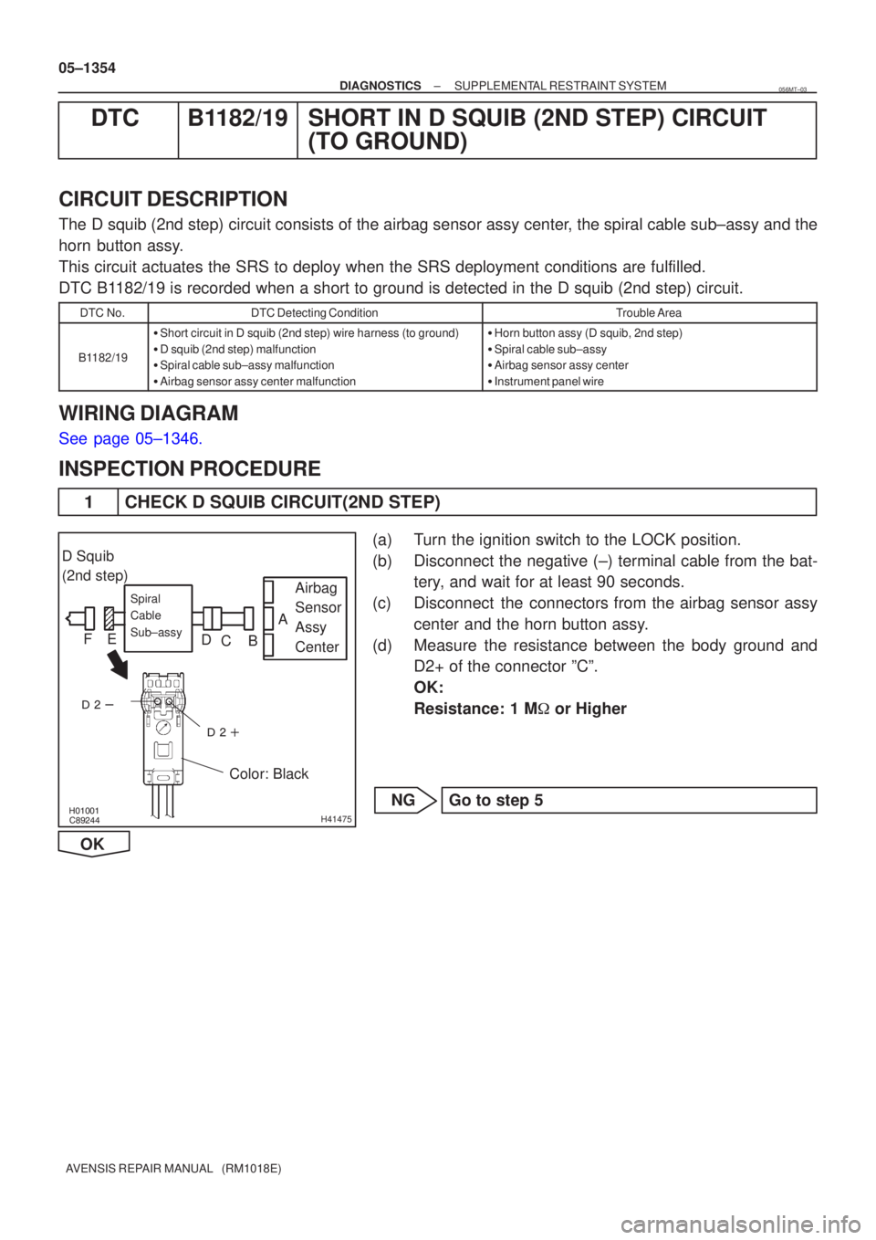
1 CHECK D SQUIB CIRCUIT(2ND STEP)
(a) Turn the ignition switch to the LOCK position.
(b) Disconnect the negative (±) terminal cable from the bat-
tery, and wait for at least 90 seconds.
(c) Disconnect the connectors from the airbag sensor assy center and the horn button assy.
(d) Measure the resistance between the body ground and D2+ of the connector ºCº.
OK:
Resistance: 1 M � or Higher
NG Go to step 5
OK
056MT±03