Page 1756 of 5135

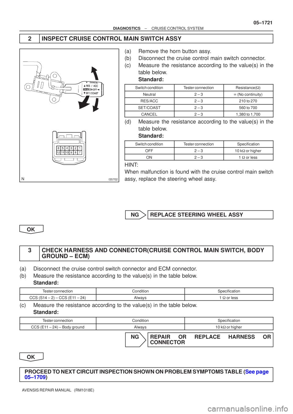
I35702
±
DIAGNOSTICS CRUISE CONTROL SYSTEM
05±1721
AVENSIS REPAIR MANUAL (RM1018E)
2INSPECT CRUISE CONTROL MAIN SWITCH ASSY
(a)Remove the horn button assy.
(b)Disconnect the cruise control main switch connector.
(c)Measure the resistance according to the value(s) in the
table below.
Standard:
Switch conditionTester connectionResistance( �)
Neutral2 ± 3� (No continuity)
RES/ACC2 ± 3210 to 270
SET/COAST2 ± 3560 to 700
CANCEL2 ± 31,380 to 1,700
(d)Measure the resistance according to the value(s) in the
table below.
Standard:
Switch conditionTester connectionSpecification
OFF2 ± 310 k� or higher
ON2 ± 31 � or less
HINT:
When malfunction is found with the cruise control main switch
assy, replace the steering wheel assy.
NGREPLACE STEERING WHEEL ASSY
OK
3CHECK HARNESS AND CONNECTOR(CRUISE CONTROL MAIN SWITCH, BODY GROUND ± ECM)
(a)Disconnect the cruise control switch connector and ECM connector.
(b)Measure the resistance according to the value(s) in the table below.
Standard:
Tester connectionConditionSpecification
CCS (S14 ± 2) ± CCS (E11 ± 24)Always1 � or less
(c)Measure the resistance according to the value(s) in the table below.
Standard:
Tester connectionConditionSpecification
CCS (E11 ± 24) ± Body groundAlways10 k� or higher
NGREPAIR OR REPLACE HARNESS OR
CONNECTOR
OK
PROCEED TO NEXT CIRCUIT INSPECTION SHOWN ON PROBLEM SYMPTOMS TABLE (See page
05±1709)
Page 2381 of 5135
160MS±01
16±36
±
COOLING RADIATOR ASSY(1AZ±FSE)
AVENSIS REPAIR MANUAL (RM1018E)
RADIATOR ASSY(1AZ±FSE)
REPLACEMENT
1.DRAIN COOLANT (See page 16±31)
2.REMOVE RADIATOR SUPPORT OPENING COVER
3.REMOVE ENGINE ROOM COVER SIDE
4.REMOVE ENGINE UNDER COVER RH
5.DISCONNECT RADIATOR HOSE INLET
6.DISCONNECT RADIATOR HOSE OUTLET
7.REMOVE RADIATOR SUPPORT UPPER
(a)Disconnect the fan w/ motor wire harness, connector and the horn connect\
or.
(b)Remove 4 bolts, the nut and the radiator support.
8.REMOVE RADIATOR ASSY
(a)Remove 2 upper support, and radiator assembly
9.REMOVE RADIATOR SUPPORT LOWER
10.REMOVE FAN ASSY W/MOTOR
(a)Remove 6 bolts and fan w/motor.
11.INSTALL FAN ASSY W/MOTOR
12.INSTALL RADIATOR SUPPORT LOWER
13.INSTALL RADIATOR ASSY
14.INSTALL RADIATOR SUPPORT UPPER
(a)Install radiator support with 2 bolts. Torque: 19 N �m (194 kgf �cm,14 ft �lbf)
15.ADD COOLANT (See page 16±31)
16.INSPECT CHECK FOR ENGINE COOLANT LEAKS (See page 16±25)
Page 2393 of 5135
160MX±01
16±24
±
COOLING RADIATOR ASSY(1AZ±FE)
AVENSIS REPAIR MANUAL (RM1018E)
RADIATOR ASSY(1AZ±FE)
REPLACEMENT
1.DRAIN COOLANT (See page 16±19)
2.REMOVE RADIATOR SUPPORT OPENING COVER
3.REMOVE ENGINE ROOM COVER SIDE
4.REMOVE ENGINE UNDER COVER RH
5.DISCONNECT RADIATOR HOSE INLET
6.DISCONNECT RADIATOR HOSE OUTLET
7.REMOVE RADIATOR SUPPORT UPPER
(a)Disconnect the fan w/ motor wire harness, connector and the horn connect\
or.
(b)Remove 4 bolts, the nut and the radiator support.
8.REMOVE RADIATOR ASSY
(a)Remove 2 upper support, and radiator assembly
9.REMOVE RADIATOR SUPPORT LOWER
10.REMOVE FAN ASSY W/MOTOR
(a)Remove 6 bolts and fan w/motor.
11.INSTALL FAN ASSY W/MOTOR
12.INSTALL RADIATOR SUPPORT LOWER
13.INSTALL RADIATOR ASSY
14.INSTALL RADIATOR SUPPORT UPPER
(a)Install radiator support with 2 bolts. Torque: 19 N �m (194 kgf �cm,14 ft �lbf)
15.ADD COOLANT (See page 16±19)
16.INSPECT CHECK FOR ENGINE COOLANT LEAKS (See page 16±13)
Page 2670 of 5135

320G5±02
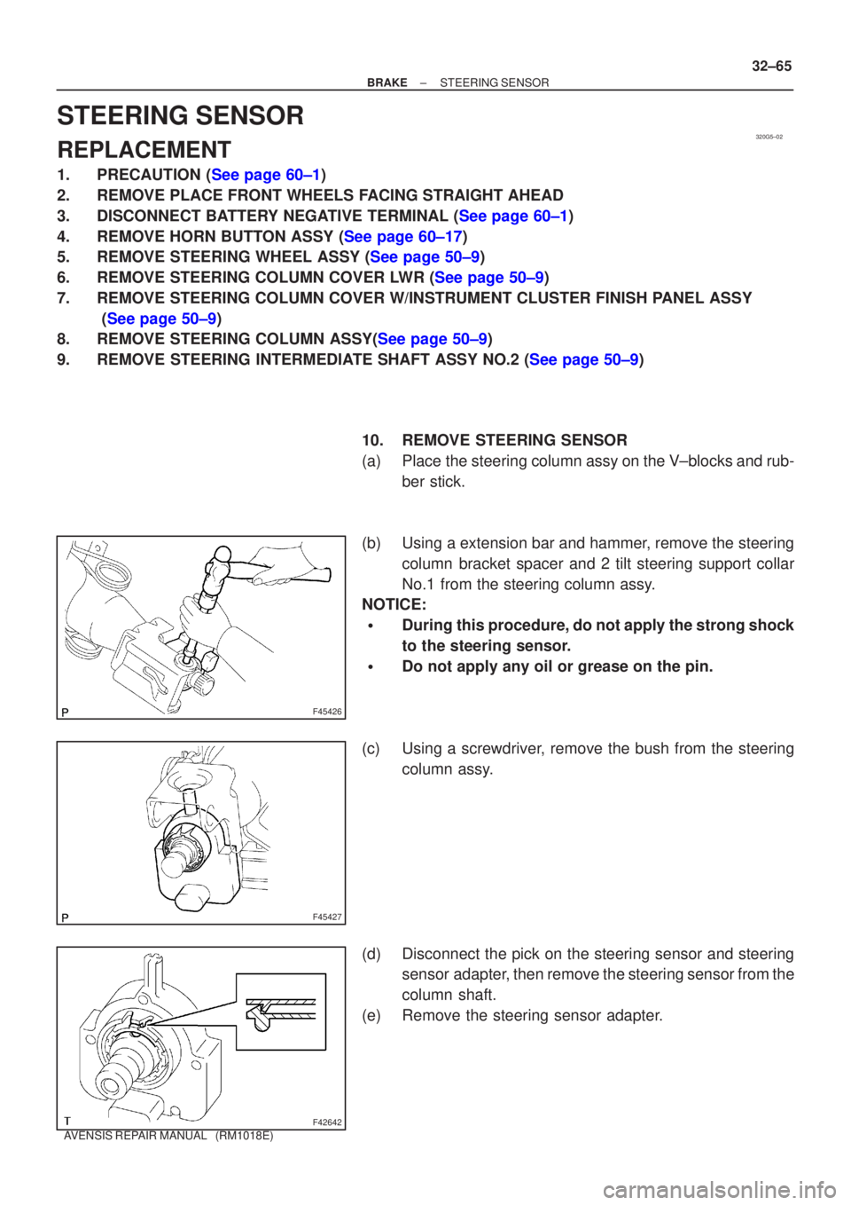
F45426
F45427
F42642
±
BRAKE STEERING SENSOR
32±65
AVENSIS REPAIR MANUAL (RM1018E)
STEERING SENSOR
REPLACEMENT
1.PRECAUTION (See page 60±1)
2. REMOVE PLACE FRONT WHEELS FACING STRAIGHT AHEAD
3.DISCONNECT BATTERY NEGATIVE TERMINAL (See page 60±1)
4.REMOVE HORN BUTTON ASSY (See page 60±17)
5.REMOVE STEERING WHEEL ASSY (See page 50±9)
6.REMOVE STEERING COLUMN COVER LWR (See page 50±9)
7. REMOVE STEERING COLUMN COVER W/INSTRUMENT CLUSTER FINISH PANEL ASSY
(See page 50±9)
8.REMOVE STEERING COLUMN ASSY(See page 50±9)
9.REMOVE STEERING INTERMEDIATE SHAFT ASSY NO.2 (See page 50±9)
10. REMOVE STEERING SENSOR
(a) Place the steering column assy on the V±blocks and rub-ber stick.
(b) Using a extension bar and hammer, remove the steering column bracket spacer and 2 tilt steering support collar
No.1 from the steering column assy.
NOTICE:
�During this procedure, do not apply the strong shock
to the steering sensor.
�Do not apply any oil or grease on the pin.
(c) Using a screwdriver, remove the bush from the steering column assy.
(d) Disconnect the pick on the steering sensor and steering sensor adapter, then remove the steering sensor from the
column shaft.
(e) Remove the steering sensor adapter.
Page 2671 of 5135

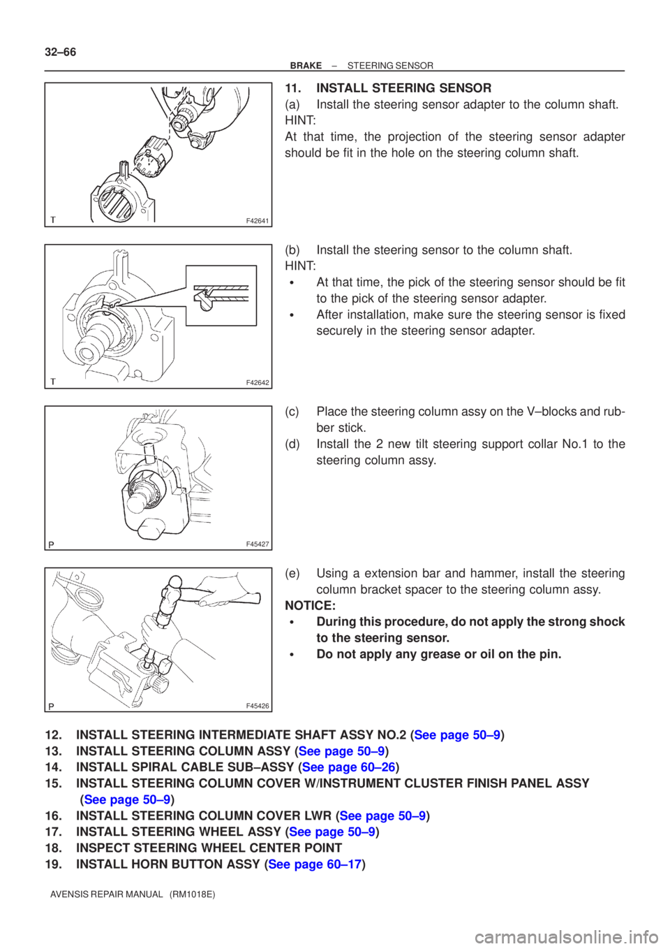
F42641
F42642
F45427
F45426
32±66
±
BRAKE STEERING SENSOR
AVENSIS REPAIR MANUAL (RM1018E)
11. INSTALL STEERING SENSOR
(a) Install the steering sensor adapter to the column shaft.
HINT:
At that time, the projection of the steering sensor adapter
should be fit in the hole on the steering column shaft.
(b) Install the steering sensor to the column shaft.
HINT:
�At that time, the pick of the steering sensor should be fit
to the pick of the steering sensor adapter.
�After installation, make sure the steering sensor is fixed
securely in the steering sensor adapter.
(c) Place the steering column assy on the V±blocks and rub- ber stick.
(d) Install the 2 new tilt steering support collar No.1 to the steering column assy.
(e) Using a extension bar and hammer, install the steering column bracket spacer to the steering column assy.
NOTICE:
�During this procedure, do not apply the strong shock
to the steering sensor.
�Do not apply any grease or oil on the pin.
12.INSTALL STEERING INTERMEDIATE SHAFT ASSY NO.2 (See page 50±9)
13.INSTALL STEERING COLUMN ASSY (See page 50±9)
14.INSTALL SPIRAL CABLE SUB±ASSY (See page 60±26)
15. INSTALL STEERING COLUMN COVER W/INSTRUMENT CLUSTER FINISH PANEL ASSY (See page 50±9)
16.INSTALL STEERING COLUMN COVER LWR (See page 50±9)
17.INSTALL STEERING WHEEL ASSY (See page 50±9)
18. INSPECT STEERING WHEEL CENTER POINT
19.INSTALL HORN BUTTON ASSY (See page 60±17)
Page 2739 of 5135
±
AUTOMATIC TRANSMISSION / TRANS TRANSMISSION CONTROL CABLE ASSY
40±73
AVENSIS REPAIR MANUAL (RM1018E)
7. INSTALL INSTRUMENT PANEL SUB±ASSY UPPER W/INSTR PNL PASS L/DOOR AIR BAG ASSY
(See page 71±11)
8.ADJUST SPIRAL CABLE SUB±ASSY (See page 60±26)
9.INSTALL STEERING WHEEL ASSY (See page 50±9)
10.INSTALL HORN BUTTON ASSY (See page 60±17)
11.INSTALL EXHAUST PIPE ASSY FRONT (1ZZ±FE ENGINE TYPE) (See page 15±2)
12.INSTALL EXHAUST PIPE ASSY FRONT (1AZ±FE/1AZ±FSE ENGINE TYPE) (See page 15±7)
13.INSPECT HORN BUTTON ASSY (See page 60±17)
14.INSPECT SRS WARNING LIGHT (See page 05±1184)
15. CHECK FOR EXHAUST GAS LEAKS
16.ADJUST SHIFT LEVER POSITION (See page 40±69)
17.INSPECT SHIFT LEVER POSITION (See page 40±69)
18.CHARGE REFRIGERANT (See page 55±38)
SST 07110±58060 (07117±58060, 07117±58070, 07117±58080, 07117±58090, 07117±78050, 07117±88060, 07117±88070, 07117±88080)
19.INSPECT LEAKAGE OF REFRIGERANT (See page 55±38)
Page 2804 of 5135
5006Y±01
Screw Case
F44801
Torx Screw
F44804
Airbag Connector
Lock Part Pull Out
F44805
CorrectWrong
±
STEERING COLUMN STEERING COLUMN ASSY
50±9
AVENSIS REPAIR MANUAL (RM1018E)
OVERHAUL
1.PRECAUTION (See page 60±1)
2. INSPECT PLACE FRONT WHEELS FACING STRAIGHT AHEAD
3.DISCONNECT BATTERY NEGATIVE TERMINAL (See page 60±1)
4.REMOVE HORN BUTTON ASSY
NOTICE:
If the airbag connector is disconnected with the ignition
switch at ON, DTCs is recorded.
(a) Using a torx socket wrench, loosen the 2 torx screws untilthe groove along the screw circumference catches on the
screw case.
(b) Pull out the horn button assy from the steering wheel and disconnect the airbag connector.
(c) Disconnect the terminal.
NOTICE:
When removing the horn button assy, take care not to pull
the airbag wire harness.
CAUTION:
�When storing the horn button assy, keep the upper
surface of the horn button assy facing upward.
�Never disassemble the horn button assy.
Page 2814 of 5135

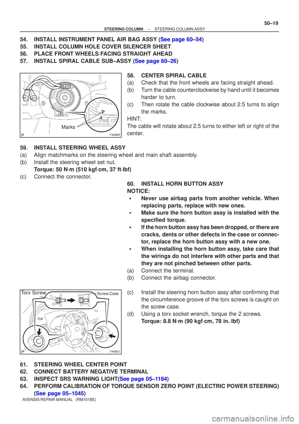
F44800
Marks
F44801
Torx ScrewScrew Case
±
STEERING COLUMN STEERING COLUMN ASSY
50±19
AVENSIS REPAIR MANUAL (RM1018E)
54.INSTALL INSTRUMENT PANEL AIR BAG ASSY (See page 60±54)
55. INSTALL COLUMN HOLE COVER SILENCER SHEET
56. PLACE FRONT WHEELS FACING STRAIGHT AHEAD
57.INSTALL SPIRAL CABLE SUB±ASSY (See page 60±26)
58. CENTER SPIRAL CABLE
(a) Check that the front wheels are facing straight ahead.
(b) Turn the cable counterclockwise by hand until it becomesharder to turn.
(c) Then rotate the cable clockwise about 2.5 turns to align the marks.
HINT:
The cable will rotate about 2.5 turns to either left or right of the
center.
59. INSTALL STEERING WHEEL ASSY
(a) Align matchmarks on the steering wheel and main shaft assembly.
(b) Install the steering wheel set nut. Torque: 50 N´m (510 kgf´cm, 37 ft´lbf)
(c) Connect the connector.
60. INSTALL HORN BUTTON ASSY
NOTICE:
�Never use airbag parts from another vehicle. When
replacing parts, replace with new ones.
�Make sure the horn button assy is installed with the
specified torque.
�If the horn button assy has been dropped, or there are
cracks, dents or other defects in the case or connec-
tor, replace the horn button assy with a new one.
�When installing the horn button assy, take care that
the wirings do not interfere with other parts and that
they are not pinched between other parts.
(a) Connect the terminal.
(b) Connect the airbag connector.
(c) Install the steering horn button assy after confirming that the circumference groove of the torx screws is caught on
the screw case.
(d) Using a torx socket wrench, torque the 2 screws. Torque: 8.8 N´m (90 kgf´cm, 78 in.´lbf)
61. STEERING WHEEL CENTER POINT
62. CONNECT BATTERY NEGATIVE TERMINAL
63.INSPECT SRS WARNING LIGHT(See page 05±1184)
64. PERFORM CALIBRATION OF TORQUE SENSOR ZERO POINT (ELECTRIC POWER STEERING) (See page 05±1045)