Page 3151 of 5135
69065±02
69±2
±
COMMUNICATION SYSTEM HORN SYSTEM
AVENSIS REPAIR MANUAL (RM1018E)
PROBLEM SYMPTOMS TABLE
SymptomSuspected AreaSee Page
Horn does not sound
1. Horn button switch
2. High pitched horn
3. Low pitched horn
4. HORN fuse
5. HORN relay
6. Wire harness±
69±3
69±3
69±3 ±
Page 3152 of 5135
69064±02
B67409
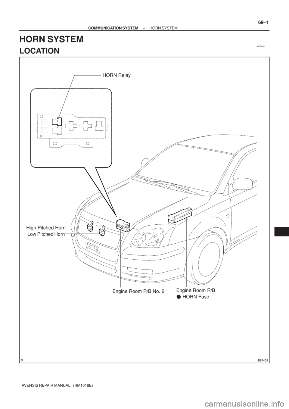
Low Pitched HornHORN Relay
High Pitched Horn
Engine Room R/B No. 2Engine Room R/B
� HORN Fuse
± COMMUNICATION SYSTEMHORN SYSTEM
69±1
AVENSIS REPAIR MANUAL (RM1018E)
HORN SYSTEM
LOCATION
Page 3155 of 5135
I35135
Engine Room Relay Block
FUSE RELAY
1. EMPS 50A
2. ±
3. A/F 20A
4. THROTTLE 10A
5. HORN 15A6. HAZARD 10A
7. ALT±S 7.5A
8. IG2 15A
9. EFI 20A
10. DCC 30A11. AM2 30A
12. MAIN 40A
13. ±
14. ±
15. ± A. FAN No.2
B. FAN No.1
C. FAN No.3
D. ±
E. ±
F. EMPS12B
CD E
F
11 1016 15
9 814
19 18 13
7 6
1217
34 5
Engine Room Relay Block ENGINE:
3ZZ±FE:
1ZZ±FE:
2AZ±FSE:
1AZ±FSE:
1AZ±FE:
A
16. RR DEF 30A
17. HTR 40A
18. RDI 30A
19. CDS 30A
ENGINE:
1CD±FTV:
1211
10 9 8 7 612
345 B
A
13
15 14
1619 18 17 20
CD
FUSE RELAY
1. MAIN 40A
2. RR DEF 30A
3. PWR HTR 25A
4. EFI 20A
5. HORN 15A6. F±HTR 25A
7. HAZARD 10A
8. AM2 30A
9. DCC 30A
10. ALT±S 7.5A11. ±
12. ±
13. ±
14. *1
15. *2 A. FAN No.1
B. FAN No.3
C. EDU
D. EFI MAIN16. RDI 40A
17. CDS 30A
18. HTR 40A
19. H/CLN 30A
20. AM1 No.1 50A
*1 VSC 25A (w/ VSC)
ABS 25A (w/o VSC)
*2 VSC 50A (w/ VSC)
ABS 40A (w/o VSC)
± WIRINGPOWER SOURCE
68±3
AVENSIS REPAIR MANUAL (RM1018E)
Page 3157 of 5135
I35750
RELAY
A. ±
B. HTR
C. SEAT HTR
D. IG1
E. TAILFUSE
1. IGN 10A
2. S/ROOF 20A
3. RR FOG 7.5A
4. FR FOG 7.5A
5. AM1 25A
6. PANEL 7.5A
7. RR WIP 20A
8. GAUGE2 7.5A
9. CIG 15A
10.HTR 10A
11. ±
12. RAD No.1 7.5A
A. HORN
B. F±HTR
C. H±LP
D. DIM
E. FAN No.2RELAY
1. H±LP HI LH 10A
2. H±LP HI RH 10A
3. H±LP LH 15A
4. H±LP RH 15AFUSE A
B
13
14
15
9
103
4
5
6
7
8
1
3
4 2CD
E
16
17
18
19
20
21
22 12 111
2
A
BCDE13. PWR SEAT 30A
14. TAIL 10A
15. OBD2 7.5A
16. P/POINT 15A
17. DOOR 25A
18. WIP 25A
19. EGU±IG 7.5A
20. S±HTR 20A
21. GAUGE1 10A
22. STOP 15A Instrument Panel Junction Block Assy
Engine Room Relay No.3 Block
± WIRINGPOWER SOURCE
68±5
AVENSIS REPAIR MANUAL (RM1018E)
Page 3225 of 5135

16.REMOVE CONSOLE PANEL SUB±ASSY UP")
B70029: 4 Clips
A/T Transaxle:
M/T Transaxle:
B66045Claw
±
INSTRUMENT PANEL/METER INSTRUMENT PANEL SUB±ASSY LOWER
71±15
AVENSIS REPAIR MANUAL (RM1018E)
16.REMOVE CONSOLE PANEL SUB±ASSY UPPER
(a)Using a moulding remover, disengage the 4 clips.
(b)Disconnect the connectors, and remove the console pan-
el sub±assy upper.
17.REMOVE INSTRUMENT CLUSTER FINISH PANEL SUB±ASSY CENTER (W/O RADIO) (See page 55±50)
18.REMOVE STEREO OPENING COVER W/BRACKET (W/O RADIO)
19.REMOVE RADIO RECEIVER ASSEMBLY W/BRACKET (See page 67±5)
20.REMOVE HORN BUTTON ASSY (See page 60±17)
21.REMOVE STEERING WHEEL ASSY (See page 50±9) SST09950±50013 (09951±05010, 09952±05010, 09953±05020, 09954±\
05021)
22.REMOVE HEADLAMP DIMMER SWITCH ASSY (See page 65±27)
23.REMOVE WINDSHIELD WIPER SWITCH ASSY (See page 66±24)
24.REMOVE INSTRUMENT PANEL UNDER COVERSUB±ASSY NO.1
(a)Remove the 2 screws .
(b)Disengage the claw and remove the instrument panel un- der cover sub±assy No.1.
25.REMOVE INSTRUMENT PANEL HOLE COVER (See page 60±54)
26.REMOVE INSTRUMENT PANEL AIR BAG ASSY (See page 60±54)
27.REMOVE STEERING COLUMN COVER LWR (See page 50±9)
Page 3230 of 5135
71±20
±
INSTRUMENT PANEL/METER INSTRUMENT PANEL SUB±ASSY LOWER
AVENSIS REPAIR MANUAL (RM1018E)
46.ADJUST SPIRAL CABLE SUB±ASSY (See page 60±26)
47.INSTALL STEERING WHEEL ASSY (See page 50±9)
48.INSTALL HORN BUTTON ASSY (See page 60±17)
49.INSPECT HORN BUTTON ASSY (See page 60±11)
50.INSPECT SRS WARNING LIGHT (See page 05±1184)
Page 3233 of 5135
B66038
Heater to Register Duct No.2
Instrument Panel Lower Assy
Cowl Side Trim
Board RH
Front Door
Scuff Plate
RH
Floor Shift
Shift Lever
Knob Sub±assy Console Panel
Sub±assy Upper
Console Panel Sub±assy Lower
Console Box Assy RR Front Door
Scuff Plate LHCowl Side Trim
Board LH
Instrument Panel Airbag Assy
Console Rear End
Panel
Radio Receiver
Assembly w/ Bracket
Windshield
Wiper Switch Assy
Instrument Panel
Hole CoverHead lamp
Dimmer Switch Assy
Instrument Panel Under
Cover Sub±assy No.2
Horn Button Assy Steering Wheel Assy
Instrument Panel Under Cover
Sub±assy No.1
H
N´m (kgf´cm, ft´lbf) : Specified torqueM/T Transaxle: A/T Transaxle:
A/T Only:
M/T Only:
50 (510, 37)
8.8 (90, 78 in.´lbf)
orEF
D
B
Bor
EF
I
or
EF
or
EF
H
HH
H
H
HH
H
H
CC
CC
H
HConsole Panel
Sub±assy Upper
18 (184, 13)
18 (184, 13)
71±8
± INSTRUMENT PANEL/METERINSTRUMENT PANEL/METER
AVENSIS REPAIR MANUAL (RM1018E)
Page 3299 of 5135

THEFT DETERRENT SYSTEM
ON±VEHICLE INSPECTION
1. OUTLINE OF THEFT DETERRENT SYSTEM
(a) When the")
730G8±01
± THEFT DETERRENT & DOOR LOCKTHEFT DETERRENT SYSTEM
73±31
AVENSIS REPAIR MANUAL (RM1018E)
THEFT DETERRENT SYSTEM
ON±VEHICLE INSPECTION
1. OUTLINE OF THEFT DETERRENT SYSTEM
(a) When the theft deterrent system detects that the vehicle is being tampered with, the system sets off
the alarm, causing the horns to sound and the lights to light up or blink in order to alert people around
the vehicle to the theft.
(b) The theft deterrent system has an active arming mode; a disarmed state, an arming preparation state,
an armed state and an alarm sounding state.
(1) Disarmed state:
�The alarm function is not operating.
�The theft deterrent system is not operating.
(2) Arming preparation state:
�The time until the system goes into the armed state.
�The theft deterrent system is not operating.
(3) Armed state:
�The theft deterrent system is operating.
HINT:
If the vehicle remains in a condition that sets off the alarm (any door remains open, engine hood remains
open, ignition switch remains directly connected) after the alarm ends, the alarm will be set off repeatedly
a maximum of 10 times for every one of the above specified conditions.
Alarm time: Approx. 27.5 sec. x 10
(4) Alarm sounding state:
When the theft deterrent system detects that the vehicle is being tampered with while in the
armed state, the system causes the horns to sound and the lights to light up or blink in order to
alert people around the vehicle to the theft.
Refer to table below for alarm method and time:
Hazard Warning LampBlinking (Cycle of flasher relay)
Alarm MethodRoom LampIlluminatingAlarm MethodVehicle HornSounding (Cycle of 0.4 sec.)
Self±power SirenSounding (Cycle of 0.4 sec.)
Alarm TimeApprox. 27.5 sec. (Maximum 10 times)
HINT:
If any of the doors are unlocked with no key in the ignition key cylinder during the armed state, a forced door
lock signal will be output (See step 3).

PROBLEM SYMPTOMS TABLE
SymptomSuspected AreaSee Page
Horn does not sound
1. Horn button switch
2. High pitched hor")


46.ADJUST SPIRAL CABLE SUB±ASSY (See page 60±26)
47.INSTALL STEERING WHEEL ASSY (See page 50±9)
4")
