Page 2976 of 5135

H42631
SST(s)
± SUPPLEMENTAL RESTRAINT SYSTEMHORN BUTTON ASSY
60±23
AVENSIS REPAIR MANUAL (RM1018E)
(3) Using 3 wire harnesses, wind each wire harness at
least")
H42629
2 Times or more
H42630SST(s)
H42631
SST(s)
± SUPPLEMENTAL RESTRAINT SYSTEMHORN BUTTON ASSY
60±23
AVENSIS REPAIR MANUAL (RM1018E)
(3) Using 3 wire harnesses, wind each wire harness at
least 2 times each around the bolts installed on the
left and right sides of the horn button assy.
CAUTION:
�Tightly wind the wire harness around the bolts so that
there is no slack.
�If there is slack in the wire harness, the horn button
assy may become loose due to the shock when the
airbag is deployed. This is highly dangerous.
(4) Face the upper surface of the horn button assy up-
ward. Separately tie the left and right sides of the
horn button assy to the disc wheel through the hub
nut holes. Position the SST(s) connector so that it
hangs downward through a hub hole in the disc
wheel.
CAUTION:
�Make sure that the wire harness is tight. It is highly
dangerous when looseness in the wire harness re-
sults in the horn button assy coming free due to the
shock from the airbag deployment.
�Always tie down the horn button assy with the pad
side facing upward. It is highly dangerous if the horn
button assy is tied down with the metal surface facing
upward as the wire harness will be cut by the shock
caused by the airbag deployment and the horn button
assy will be thrown into the air.
NOTICE:
The disc wheel will be marked by the airbag deployment,
so use a redundant disc wheel.
(d) Install the SST(s).
CAUTION:
Place the disc wheel on the level ground.
(1) Connect the connector of the SST(s).
SST 09082±00700
NOTICE:
To avoid damaging the SST(s) connector and wire harness,
do not lock the secondary lock of the twin lock. Also, se-
cure some slack for the SST(s) wire harness inside the disc
wheel.
Page 2977 of 5135
 or moreBattery
SST(s)
H42633Weight
X Y
Y
H40013
Inner Diam.
Tires
(3 or More)Width 60±24
± SUPPLEMENTAL RESTRAINT SYSTEMHORN BUTTON ASSY
AVENSIS REPAIR MANUAL (RM1018E)
(2) Move")
H4263210 m (33 ft) or moreBattery
SST(s)
H42633Weight
X Y
Y
H40013
Inner Diam.
Tires
(3 or More)Width 60±24
± SUPPLEMENTAL RESTRAINT SYSTEMHORN BUTTON ASSY
AVENSIS REPAIR MANUAL (RM1018E)
(2) Move the SST(s) to at least 10 m (33 ft) away from
the horn button assy tied down to the disc wheel.
(e) Cover the horn button assy with a cardboard box or tires.
�Covering method using a cardboard box:
Cover the horn button assy with the cardboard box
and weigh the cardboard box down in 4 places with
at least 190 N (20 kg, 44 lb).
Size of cardboard box:
Must exceed the following dimensions:
X = 460 mm (18.11 in.)
Y = 650 mm (25.59 in.)
NOTICE:
�When the dimension Y of the cardboard box exceeds
the diameter of the disc wheel with tire to which the
horn button assy is tied, X should be the following
size.
X = 460 mm (18.11 in.) + width of tire
�If a cardboard box smaller than the specified size is
used, the cardboard box will be broken by the shock
from the airbag deployment.
�Covering method using tires:
Place at least 3 tires with no disc wheels on top of
the tire with disc wheel to which the horn button assy
is tied.
Tire size: Must exceed the following dimensions
Width: 185 mm (7.28 in.)
Inner diameter: 360 mm (14.17 in.)
CAUTION:
Do not use tires with disc wheels.
NOTICE:
�The tires may be marked by the airbag deployment,
so use a redundant tires.
�Do not place the SST(s) connector under the tire be-
cause the SST(s) connector could be damaged.
Page 2978 of 5135
 or moreBattery
SST(s)
H42635
± SUPPLEMENTAL RESTRAINT SYSTEMHORN BUTTON ASSY
60±25
AVENSIS REPAIR MANUAL (RM1018E)
(f) Deploy the airbag.
(1) Connect the red clip of the SST(s)")
H4263210 m (33 ft) or moreBattery
SST(s)
H42635
± SUPPLEMENTAL RESTRAINT SYSTEMHORN BUTTON ASSY
60±25
AVENSIS REPAIR MANUAL (RM1018E)
(f) Deploy the airbag.
(1) Connect the red clip of the SST(s) to the battery
positive (+) terminal and the black clip of the SST(s)
to the battery negative (±) terminal.
(2) Check that no one is within a 10 m (33 ft) radius of
the disc wheel which the horn button assy is tied to.
(3) Press the activation switch of the SST(s) and
deploy the airbag.
HINT:
The airbag is deployed as the LED of the SST(s) activation
switch comes on.
(g) Dispose of the horn button assy.
CAUTION:
�The horn button assy is extremely hot when the air-
bag is deployed, so do not touch it for at least 30 min-
utes after deployment.
�Use gloves and safety glasses when handling the
horn button assy with the deployed airbag.
�Do not apply water, etc. to the horn button assy with
the deployed airbag.
�Always wash your hands with water after completing
the operation.
(1) Remove the horn button assy from the disc wheel.
(2) Place the horn button assy in a plastic bag, tie the
end tightly and dispose of it as other general parts
disposal.
Page 2979 of 5135
6009P±04
H42622
H43002
±
SUPPLEMENTAL RESTRAINT SYSTEM HORN BUTTON ASSY
60±17
AVENSIS REPAIR MANUAL (RM1018E)
REPLACEMENT
1.PRECAUTION (See page 60±1)
2.DISCONNECT BATTERY NEGATIVE TERMINAL (See page 60±1)
3. REMOVE HORN BUTTON ASSY
(a) Place the front wheels facing straight ahead.
(b) Using a torx socket wrench (T30), loosen the 2 torxscrews until the groove along the screw circumference
catches on the screw case.
(c) Pull out the horn button assy from the steering wheel assy and support the horn button assy with one hand as shown
in the illustration.
NOTICE:
When removing the horn button assy, do not pull the airbag
wire harness.
(d) Using a screwdriver, disconnect the airbag connectors.
(e) Disconnect the horn connector.
(f) Remove the horn button assy.
Page 2980 of 5135
H43003
H42615
60±18
±
SUPPLEMENTAL RESTRAINT SYSTEM HORN BUTTON ASSY
AVENSIS REPAIR MANUAL (RM1018E)
4. INSTALL HORN BUTTON ASSY
(a) Support the horn button assy with the hand as shown in the illustration.
(b) Connect the airbag connectors.
(c) Connect the horn connector.
(d) Confirm that the circumference groove of the torx screw fits in the screw case, and place the horn button assy onto
the steering wheel assy.
(e) Using a torx socket wrench (T 30), install the 2 screws. Torque: 8.8 N �m (90 kgf �cm, 78 in. �lbf)
5.INSPECT HORN BUTTON ASSY (See page 60±11)
(a) Do a visual check which includes the following items with the horn button assy installed in the vehicle:
Cuts, minute cracks or marked discoloration on the horn
button assy top surface and in the grooved portion.
6.INSPECT SRS WARNING LIGHT (See page 05±1184)
Page 2981 of 5135
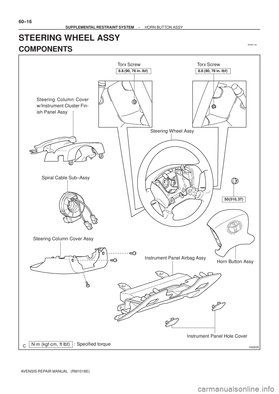
6009O±06
H42639N�m (kgf�cm, ft�lbf): Specified torqueTorx Screw
Steering Column Cover
w/Instrument Cluster Fin-
ish Panel Assy
Torx Screw
Horn Button Assy Steering Column Cover AssySpiral Cable Sub±Assy
Steering Wheel Assy
50 (510, 37)
Instrument Panel Airbag Assy
Instrument Panel Hole Cover
8.8 (90, 78 in.�lbf)8.8 (90, 78 in.�lbf)
60±16
± SUPPLEMENTAL RESTRAINT SYSTEMHORN BUTTON ASSY
AVENSIS REPAIR MANUAL (RM1018E)
STEERING WHEEL ASSY
COMPONENTS
Page 2982 of 5135

ON±VEHICLE INSPECTION
1. HORN B")
600JV±01
H42615
H42616
H43001
Horn Button Contact Plate
H42618
±
SUPPLEMENTAL RESTRAINT SYSTEM SUPPLEMENTAL RESTRAINT SYSTEM
60±11
AVENSIS REPAIR MANUAL (RM1018E)
ON±VEHICLE INSPECTION
1. HORN BUTTON ASSY (VEHICLES NOT INVOLVED IN
COLLISION)
(a)Do a diagnostic system check (See page 05±1184).
(b) Do a visual check which includes the following items with the horn button assy installed in the vehicle:
Cuts, minute cracks or marked discoloration on the horn
button assy top surface and in the grooved portion.
2. HORN BUTTON ASSY (VEHICLE INVOLVED IN COLLI- SION AND AIRBAG IS NOT DEPLOYED)
(a)Do a diagnostic system check (See page 05±1184).
(b) Do a visual check of the horn button assy removed from the vehicle:
�Cuts, minute cracks or marked discoloration on the
horn button assy top surface and in the grooved
portion.
�Cuts and cracks in wire harness, and chipping in
connectors.
�Deformation of the horn button assy.
�The deformation of the horn button contact plate of
the steering wheel assy.
HINT:
�If the horn button contact plate of the steering wheel assy
is deformed, replace it with a new one. Always replace the
steering wheel assy with a new one.
�Never repair it in order for reuse or replacement.
�There should be no interference between the horn button
assy and steering wheel assy, and the clearance should
be uniform all the way around when the new horn button
assy is installed on the steering wheel assy.
CAUTION:
For removal and installation procedures of the horn button
assy, see ºReplacementº on page 60±17, and be sure to fol-
low the correct procedure.
Page 2985 of 5135

10. INSTRUMENT PANEL AIRBAG ASSY (VEHICLE IN- VOLVED IN COLLISION AND AIRBAG IS NO")
H42657
H42659
60±14
±
SUPPLEMENTAL RESTRAINT SYSTEM SUPPLEMENTAL RESTRAINT SYSTEM
AVENSIS REPAIR MANUAL (RM1018E)
10. INSTRUMENT PANEL AIRBAG ASSY (VEHICLE IN- VOLVED IN COLLISION AND AIRBAG IS NOT
DEPLOYED)
(a)Do a diagnostic system check (See page 05±1184).
(b) Do a visual check of the instrument panel airbag assy re- moved from the vehicle:
�Cuts, minute cracks or marked discoloration on the
instrument panel airbag assy.
HINT:
�Never repair it in order for reuse or replacement.
�There should be no interference between the horn button
assy and steering wheel assy, and the clearance should
be uniform all the around when the new horn button assy
is installed on the steering wheel assy.
CAUTION:
For removal and installation procedures of the horn button
assy, see ºReplacementº on page 60±54, and be sure to fol-
low the correct procedure.
11. AIRBAG SENSOR ASSY CENTER (VEHICLE NOT INVOLVED IN COLLISION)
(a)Do a diagnostic system check (See page 05±1184).
12. AIRBAG SENSOR ASSY CENTER (VEHICLE INVOLVED IN COLLISION AND AIRBAG IS NOT DEPLOYED)
(a)Do a diagnostic system check (See page 05±1184).
13. AIRBAG SENSOR ASSY CENTER (VEHICLE INVOLVED IN COLLISION AND AIRBAG IS
DEPLOYED)
(a)Replace the airbag sensor assy center (See page 60±62).
14. AIRBAG FRONT SENSOR (VEHICLE NOT INVOLVED IN COLLISION)
(a)Do a diagnostic system check (See page 05±1184).
15. AIRBAG FRONT SENSOR (VEHICLE INVOLVED IN COLLISION)
(a)Do a diagnostic system check (See page 05±1184).
(b) When the headlamp of the vehicle or its periphery is damaged, check if t\
here is any damage to the airbag front sensor. If there are any defects as mentioned below, replace the airbag front sensor with
a new one:
If there are any defects as mentioned below, replace the airbag front sensor with a new one:
�Cracks, dents or chips in the case.
�Cracks, dents, chips and scratches in the connector.
�Peeling off of the label or damage to the serial number.
16. AIRBAG FRONT SENSOR (VEHICLE INVOLVED IN COLLISION AND AIRBAG IS DEPLOYED)
(a)Replace the airbag front sensor assy (See page 60±64).
17. SIDE AIRBAG SENSOR ASSY (VEHICLES NOT INVOLVED IN COLLISION)
(a)Do a diagnostic system check (See page 05±1184).

REPLACEMENT
1.PRECAUTION (See page 60±1)
2.DISCONNECT BATTERY NEGATIVE TERMINAL (See")

4. INSTALL HORN BUTTON ASSY
(a) Support the horn button assy with the hand as shown in the illu")