Page 3301 of 5135

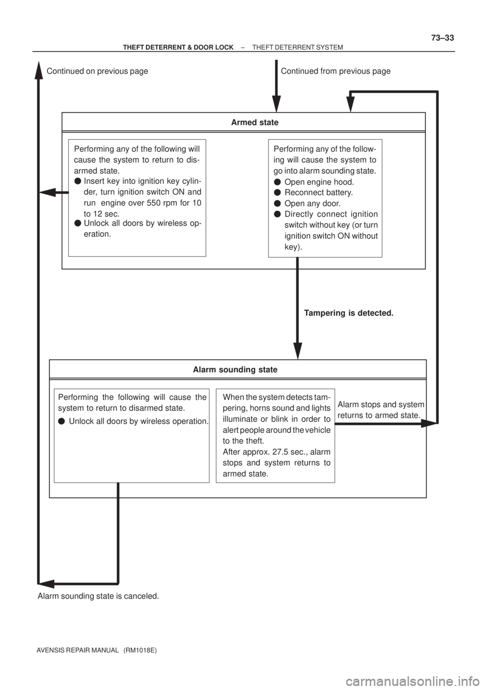
Alarm sounding state
Performing the following will cause the
system to return to disarmed state.When the system detects tam-
pering, horns sound and lights
illuminate or blink in order to
alert people around the vehicle
to the theft.
After approx. 27.5 sec., alarm
stops and system returns to
armed state.
Armed state
Performing any of the following will
cause the system to return to dis-
armed state.Performing any of the follow-
ing will cause the system to
go into alarm sounding state.
Alarm sounding state is canceled.Tampering is detected.
Alarm stops and system
returns to armed state.
Continued from previous page Continued on previous page
�Insert key into ignition key cylin-
der, turn ignition switch ON and
run engine over 550 rpm for 10
to 12 sec.
�Unlock all doors by wireless op-
eration.Directly connect ignition
switch without key (or turn
ignition switch ON without
key). �Open engine hood.
�Reconnect battery.
�Open any door.
�
�Unlock all doors by wireless operation.
± THEFT DETERRENT & DOOR LOCKTHEFT DETERRENT SYSTEM
73±33
AVENSIS REPAIR MANUAL (RM1018E)
Page 5094 of 5135

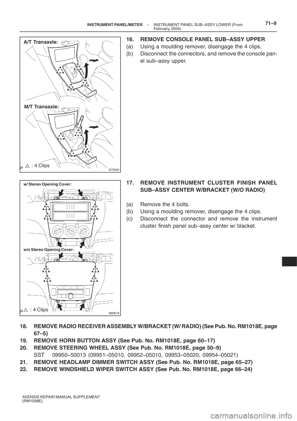
B70029: 4 Clips
A/T Transaxle:
M/T Transaxle:
B80618
w/ Stereo Opening Cover:
w/o Stereo Opening Cover:
: 4 Clips
– INSTRUMENT PANEL/METERINSTRUMENT PANEL SUB–ASSY LOWER (From
February, 2004)71–9
AVENSIS REPAIR MANUAL SUPPLEMENT
(RM1098E)
16. REMOVE CONSOLE PANEL SUB–ASSY UPPER
(a) Using a moulding remover, disengage the 4 clips.
(b) Disconnect the connectors, and remove the console pan-
el sub–assy upper.
17. REMOVE INSTRUMENT CLUSTER FINISH PANEL
SUB–ASSY CENTER W/BRACKET (W/O RADIO)
(a) Remove the 4 bolts.
(b) Using a moulding remover, disengage the 4 clips.
(c) Disconnect the connector and remove the instrument
cluster finish panel sub–assy center w/ blacket.
18. REMOVE RADIO RECEIVER ASSEMBLY W/BRACKET (W/ RADIO) (See Pub. No. RM1018E, page
67–5)
19. REMOVE HORN BUTTON ASSY (See Pub. No. RM1018E, page 60–17)
20. REMOVE STEERING WHEEL ASSY (See Pub. No. RM1018E, page 50–9)
SST 09950–50013 (09951–05010, 09952–05010, 09953–05020, 09954–05021)
21. REMOVE HEADLAMP DIMMER SWITCH ASSY (See Pub. No. RM1018E, page 65–27)
22. REMOVE WINDSHIELD WIPER SWITCH ASSY (See Pub. No. RM1018E, page 66–24)
Page 5099 of 5135
71–14– INSTRUMENT PANEL/METERINSTRUMENT PANEL SUB–ASSY LOWER (From
February, 2004)
AVENSIS REPAIR MANUAL SUPPLEMENT
(RM1098E)
45. INSTALL INSTRUMENT PANEL REGISTER ASSY NO.2
46. ADJUST SPIRAL CABLE SUB–ASSY (See Pub. No. RM1018E, page 60–26)
47. INSTALL STEERING WHEEL ASSY (See Pub. No. RM1018E, page 50–9)
48. INSTALL HORN BUTTON ASSY (See Pub. No. RM1018E, page 60–17)
49. INSPECT HORN BUTTON ASSY (See Pub. No. RM1018E, page 60–11)
50. INSPECT SRS WARNING LIGHT (See Pub. No. RM1018E, page 05–1184)