Page 2115 of 5135
A62816
84 2 59
7 3 1 6 10
A62823
Paint Mark
90�
Front
A62150
Camshaft No. 2
Camshaft
A62825
62 4 8
51 3 7 11
10
9
A10079
14±88
± ENGINE MECHANICALCYLINDER HEAD GASKET (1ZZ±FE/3ZZ±FE)
AVENSIS REPAIR MANUAL (RM1018E)
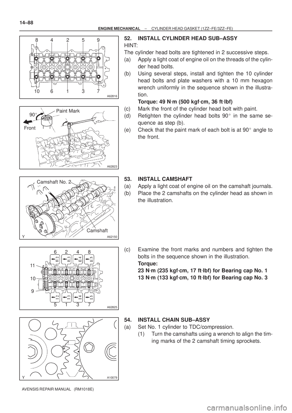
52. INSTALL CYLINDER HEAD SUB±ASSY
HINT:
The cylinder head bolts are tightened in 2 successive steps.
(a) Apply a light coat of engine oil on the threads of the cylin-
der head bolts.
(b) Using several steps, install and tighten the 10 cylinder
head bolts and plate washers with a 10 mm hexagon
wrench uniformly in the sequence shown in the illustra-
tion.
Torque: 49 N�m (500 kgf�cm, 36 ft�lbf)
(c) Mark the front of the cylinder head bolt with paint.
(d) Retighten the cylinder head bolts 90� in the same se-
quence as step (b).
(e) Check that the paint mark of each bolt is at 90� angle to
the front.
53. INSTALL CAMSHAFT
(a) Apply a light coat of engine oil on the camshaft journals.
(b) Place the 2 camshafts on the cylinder head as shown in
the illustration.
(c) Examine the front marks and numbers and tighten the
bolts in the sequence shown in the illustration.
Torque:
23 N�m (235 kgf�cm, 17 ft�lbf) for Bearing cap No. 1
13 N�m (133 kgf�cm, 10 ft�lbf) for Bearing cap No. 3
54. INSTALL CHAIN SUB±ASSY
(a) Set No. 1 cylinder to TDC/compression.
(1) Turn the camshafts using a wrench to align the tim-
ing marks of the 2 camshaft timing sprockets.
Page 2130 of 5135
A79033
±
ENGINE MECHANICAL ENGINE(1AZ±FSE)
14±183
AVENSIS REPAIR MANUAL (RM1018E)
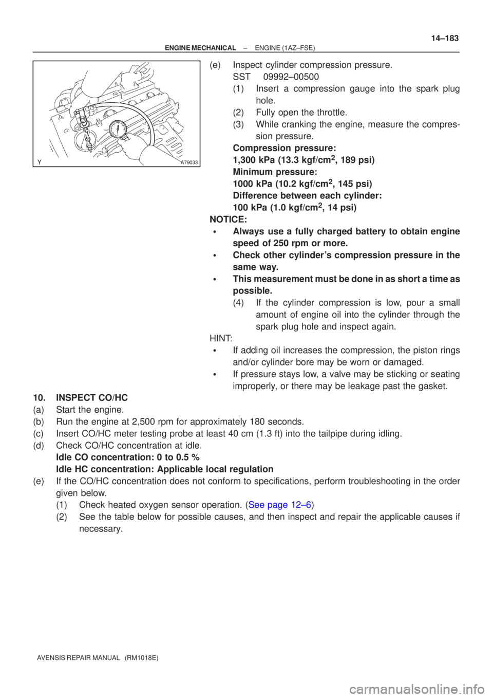
(e)Inspect cylinder compression pressure.
SST09992±00500
(1)Insert a compression gauge into the spark plughole.
(2)Fully open the throttle.
(3)While cranking the engine, measure the compres- sion pressure.
Compression pressure:
1,300 kPa (13.3 kgf/cm
2, 189 psi)
Minimum pressure:
1000 kPa (10.2 kgf/cm
2, 145 psi)
Difference between each cylinder:
100 kPa (1.0 kgf/cm
2, 14 psi)
NOTICE:
�Always use a fully charged battery to obtain engine
speed of 250 rpm or more.
�Check other cylinder's compression pressure in the
same way.
�This measurement must be done in as short a time as
possible.
(4)If the cylinder compression is low, pour a small amount of engine oil into the cylinder through the
spark plug hole and inspect again.
HINT:
�If adding oil increases the compression, the piston rings
and/or cylinder bore may be worn or damaged.
�If pressure stays low, a valve may be sticking or seating
improperly, or there may be leakage past the gasket.
10.INSPECT CO/HC
(a)Start the engine.
(b)Run the engine at 2,500 rpm for approximately 180 seconds.
(c)Insert CO/HC meter testing probe at least 40 cm (1.3 ft) into the tail\
pipe during idling.
(d)Check CO/HC concentration at idle. Idle CO concentration: 0 to 0.5 %
Idle HC concentration: Applicable local regulation
(e)If the CO/HC concentration does not conform to specifications, perform troubleshooting in the order given below.
(1)Check heated oxygen sensor operation. (See page 12±6)
(2) See the table below for possible causes, and then inspect and repair the applicable causes ifnecessary.
Page 2147 of 5135
A77302
14±162
±
ENGINE MECHANICAL CYLINDER HEAD GASKET(1AZ±FE)
AVENSIS REPAIR MANUAL (RM1018E)
22.REMOVE ENGINE SERVICE COVER BRACKET RH (RHD(W/ AIR CONDITIONER) STEERING POSITION TYPE)
(a)Remove the bolt and the engine service cover bracket RH.
23.REMOVE CYLINDER HEAD COVER SUB±ASSY (See page 14±139)
24.SET NO. 1 CYLINDER TO TDC/COMPRESSION (See page 14±139)
25.REMOVE ENGINE MOUNTING BRACKET NO.2 RH (See page 14±139)
26.REMOVE TRANSVERSE ENGINE ENGINE MOUNTING INSULATOR (See page 14±139)
27.REMOVE CRANKSHAFT PULLEY (See page 14±139)
SST09213±54015 (91651±60855), 09330±00021, 09950±50013 (0995\
1±05010, 09952±05010, 09953±05020, 09954±05021)
28.REMOVE CHAIN TENSIONER ASSY NO.1 (See page 14±139)
29.REMOVE CRANKSHAFT POSITION SENSOR (See page 18±17)
30.REMOVE OIL PAN SUB±ASSY (See page 14±139) SST09032±00100
31.REMOVE V±RIBBED BELT TENSIONER ASSY (See page 14±139)
32.REMOVE TIMING CHAIN OR BELT COVER SUB±ASSY (See page 14±139)
33.REMOVE CRANKSHAFT POSITION SENSOR PLATE NO.1
34.REMOVE CHAIN TENSIONER SLIPPER
35.REMOVE CHAIN VIBRATION DAMPER NO.1
36.REMOVE TIMING CHAIN GUIDE (See page 14±139)
37.REMOVE CHAIN SUB±ASSY
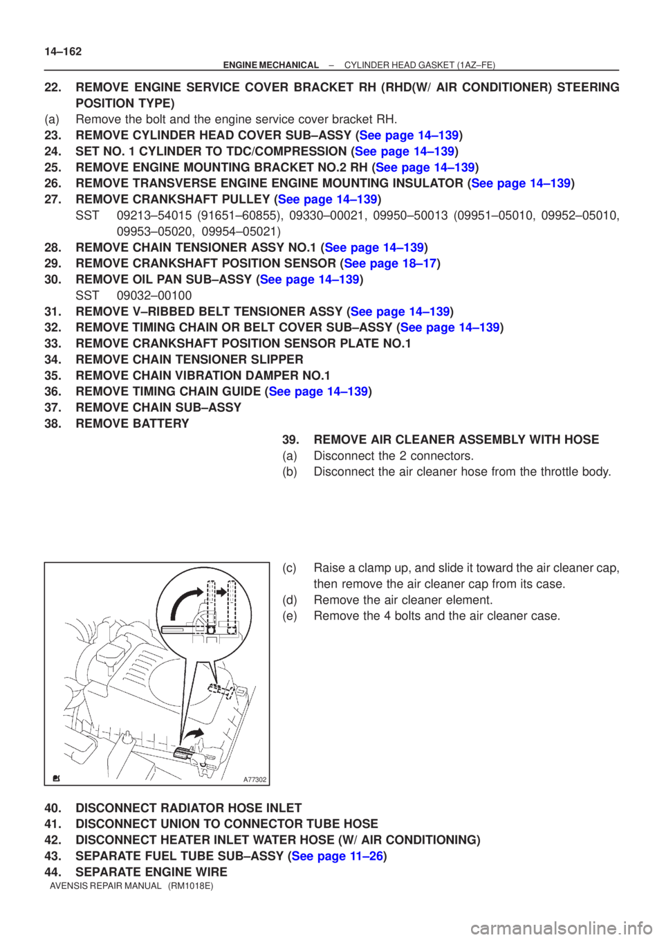
38.REMOVE BATTERY 39.REMOVE AIR CLEANER ASSEMBLY WITH HOSE
(a)Disconnect the 2 connectors.
(b)Disconnect the air cleaner hose from the throttle body.
(c)Raise a clamp up, and slide it toward the air cleaner cap,then remove the air cleaner cap from its case.
(d)Remove the air cleaner element.
(e)Remove the 4 bolts and the air cleaner case.
40.DISCONNECT RADIATOR HOSE INLET
41.DISCONNECT UNION TO CONNECTOR TUBE HOSE
42.DISCONNECT HEATER INLET WATER HOSE (W/ AIR CONDITIONING)
43.SEPARATE FUEL TUBE SUB±ASSY (See page 11±26)
44. SEPARATE ENGINE WIRE
Page 2162 of 5135
A77283
A77284
A77285
Unleaded Gasoline
Timing
Marks
�eaded Gasoline
Timing
Marks
Timing
Marks
Timing
Marks
± ENGINE MECHANICALCHAIN SUB±ASSY (1AZ±FE)
14±141
AVENSIS REPAIR MANUAL (RM1018E)
19. REMOVE ENGINE SERVICE COVER BRACKET RH (RHD(W/ AIR CONDITIONER) STEERING
POSITION TYPE)
(a) Remove the bolt and the engine service cover bracket RH.
20. REMOVE IGNITION COIL ASSY
(a) Remove the 4 bolts and 4 ignition coils.
21. REMOVE CYLINDER HEAD COVER SUB±ASSY
(a) Disconnect the 2 PCV hoses from the cylinder head cov-
er.
(b) Remove the 8 bolts and 2 nuts, and then remove the cylin-
der head cover and gasket.
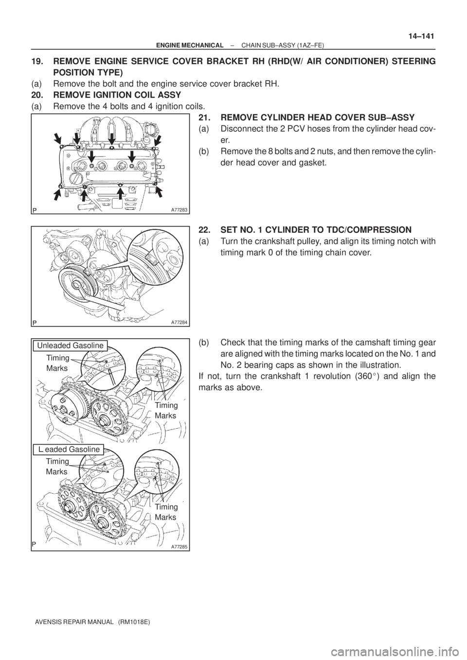
22. SET NO. 1 CYLINDER TO TDC/COMPRESSION
(a) Turn the crankshaft pulley, and align its timing notch with
timing mark 0 of the timing chain cover.
(b) Check that the timing marks of the camshaft timing gear
are aligned with the timing marks located on the No. 1 and
No. 2 bearing caps as shown in the illustration.
If not, turn the crankshaft 1 revolution (360�) and align the
marks as above.
Page 2168 of 5135
A77285
Unleaded Gasoline
Timing
Marks
Leaded Gasoline
Timing
Marks
Timing
Marks
Timing
Marks
A52505
A77388
SST
± ENGINE MECHANICALCHAIN SUB±ASSY (1AZ±FE)
14±147
AVENSIS REPAIR MANUAL (RM1018E)
39. INSTALL CRANKSHAFT TIMING GEAR OR SPROCKET
40. SET NO. 1 CYLINDER TO TDC/COMPRESSION
(a) Turn the camshafts with a wrench on the hexagonal lobe,
and align the timing marks of the camshaft timing gear
with each timing mark located on the No. 1 and No. 2
bearing caps as shown in the illustration.
(b) Using the crankshaft pulley bolt, turn the crankshaft and
position the key on the crankshaft upward.
41. INSTALL CHAIN VIBRATION DAMPER NO.1
42. INSTALL CHAIN SUB±ASSY
Page 2183 of 5135
A77307
A77346
A77284
A77345
Timing
Marks
Timing
Marks 14±224
± ENGINE MECHANICALCHAIN SUB±ASSY (1AZ±FSE)
AVENSIS REPAIR MANUAL (RM1018E)
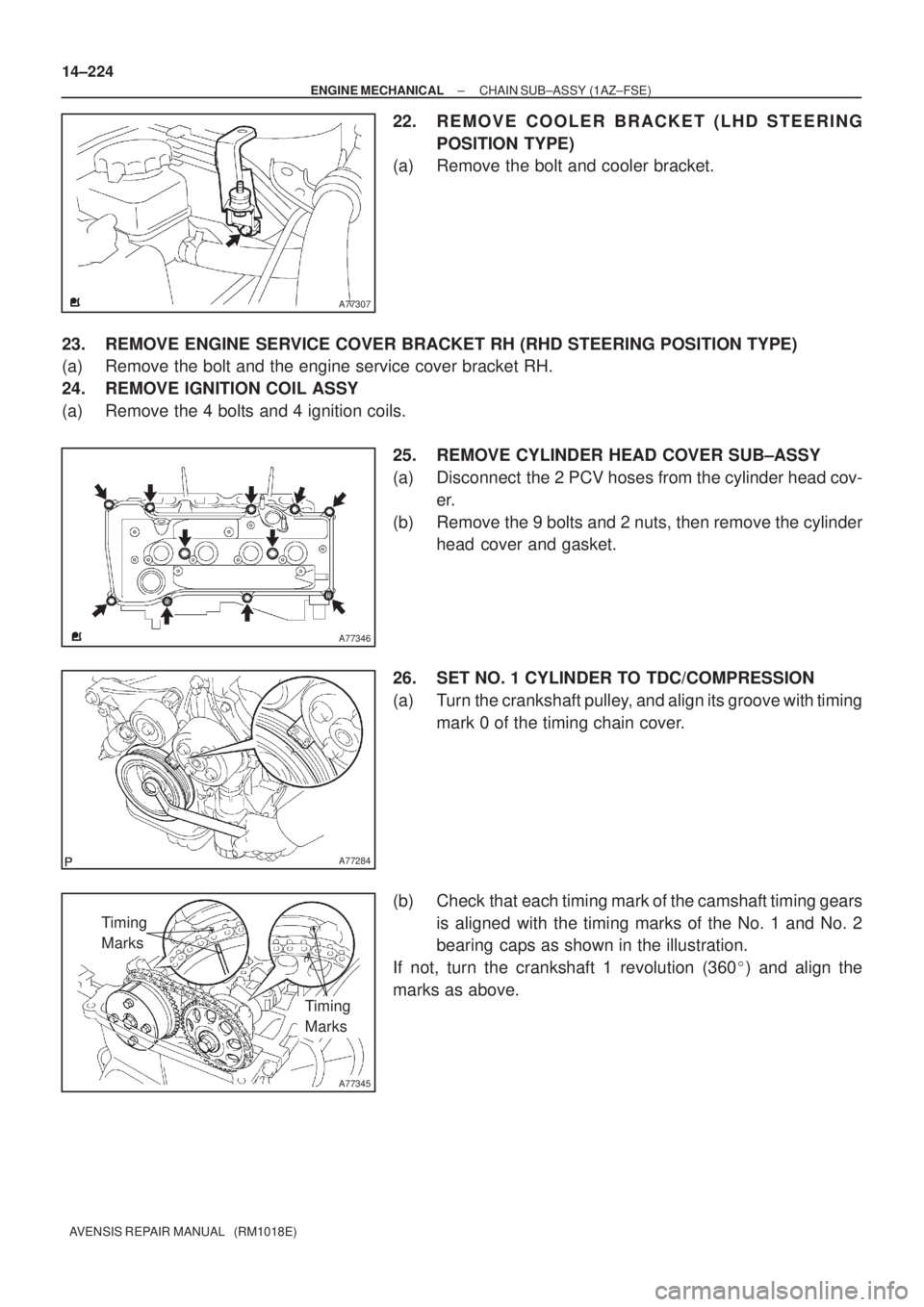
22. REMOVE COOLER BRACKET (LHD STEERING
POSITION TYPE)
(a) Remove the bolt and cooler bracket.
23. REMOVE ENGINE SERVICE COVER BRACKET RH (RHD STEERING POSITION TYPE)
(a) Remove the bolt and the engine service cover bracket RH.
24. REMOVE IGNITION COIL ASSY
(a) Remove the 4 bolts and 4 ignition coils.
25. REMOVE CYLINDER HEAD COVER SUB±ASSY
(a) Disconnect the 2 PCV hoses from the cylinder head cov-
er.
(b) Remove the 9 bolts and 2 nuts, then remove the cylinder
head cover and gasket.
26. SET NO. 1 CYLINDER TO TDC/COMPRESSION
(a) Turn the crankshaft pulley, and align its groove with timing
mark 0 of the timing chain cover.
(b) Check that each timing mark of the camshaft timing gears
is aligned with the timing marks of the No. 1 and No. 2
bearing caps as shown in the illustration.
If not, turn the crankshaft 1 revolution (360�) and align the
marks as above.
Page 2189 of 5135
A77345
Timing
Marks
Timing
Marks
A52505
A77388
SST
A77389
Timing MarksMark Links
Timing Mark
14±230
± ENGINE MECHANICALCHAIN SUB±ASSY (1AZ±FSE)
AVENSIS REPAIR MANUAL (RM1018E)
43. INSTALL CRANKSHAFT TIMING GEAR OR SPROCKET
44. SET NO. 1 CYLINDER TO TDC/COMPRESSION
(a) Turn the camshafts with a wrench on the hexagonal lobe,
and align the timing marks of the camshaft timing gear
with each timing mark located on the No. 1 and No. 2
bearing caps as shown in the illustration.
(b) Using the crankshaft pulley bolt, turn the crankshaft and
position the key on the crankshaft upward.
45. INSTALL CHAIN VIBRATION DAMPER NO.1
Torque: 9.0 N�m (92 kgf�cm, 80 in.�lbf)
46. INSTALL CHAIN SUB±ASSY
(a) Using SST, install the sprocket.
(b) Align the mark links (gold or yellow colored links) with
each timing mark located on the camshaft timing gears,
and install the chain.
Page 2226 of 5135
141BL±01
A77339
A77343
No. 1 Cylinder TDC / CompressionIN
EX
14±186
±
ENGINE MECHANICAL VALVE CLEARANCE(1AZ±FSE)
AVENSIS REPAIR MANUAL (RM1018E)
VALVE CLEARANCE(1AZ±FSE)
ADJUSTMENT
1.DISCHARGE FUEL SYSTEM PRESSURE (See page 11±33)
2.REMOVE RADIATOR SUPPORT OPENING COVER
3.REMOVE ENGINE ROOM COVER SIDE
4.REMOVE ENGINE UNDER COVER RH 5.REMOVE ENGINE COVER SUB±ASSY NO.1
(a)Remove the 2 nuts and the engine cover No. 1.
6.REMOVE FUEL PRESSURE PULSATION DAMPER ASSY
7.REMOVE FUEL TUBE SUB±ASSY (See page 11±33)
8.REMOVE FUEL PIPE SUB±ASSY NO.1 (See page 11±52) SST 09023±12900
9. REMOVE IGNITION COIL ASSY
(a) Remove the 4 bolts and the ignition coils.
10.REMOVE CYLINDER HEAD COVER SUB±ASSY (See page 14±240)
11.SET NO. 1 CYLINDER TO TDC/COMPRESSION (See page 14±240)
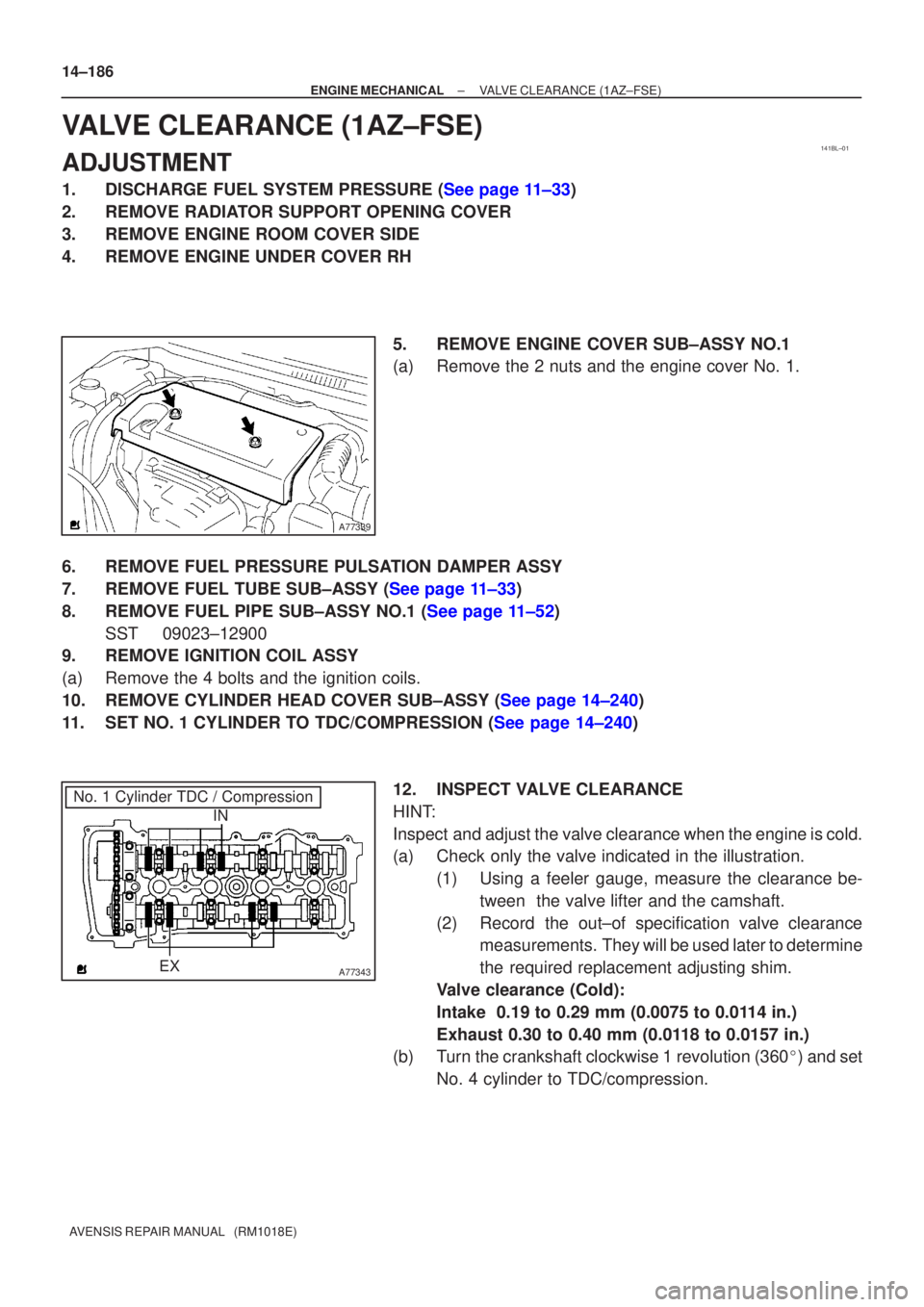
12. INSPECT VALVE CLEARANCE
HINT:
Inspect and adjust the valve clearance when the engine is cold.
(a) Check only the valve indicated in the illustration.(1) Using a feeler gauge, measure the clearance be-tween the valve lifter and the camshaft.
(2) Record the out±of specification valve clearance measurements. They will be used later to determine
the required replacement adjusting shim.
Valve clearance (Cold):
Intake 0.19 to 0.29 mm (0.0075 to 0.0114 in.)
Exhaust 0.30 to 0.40 mm (0.0118 to 0.0157 in.)
(b) Turn the crankshaft clockwise 1 revolution (360 �) and set
No. 4 cylinder to TDC/compression.