Page 4642 of 5135
A87962
A09609
A09680
SST
A09611
A09606
− ENGINE MECHANICALTIMING BELT (1CD−FTV)(From September, 2003)
14−141
AVENSIS Supplement (RM1045E)
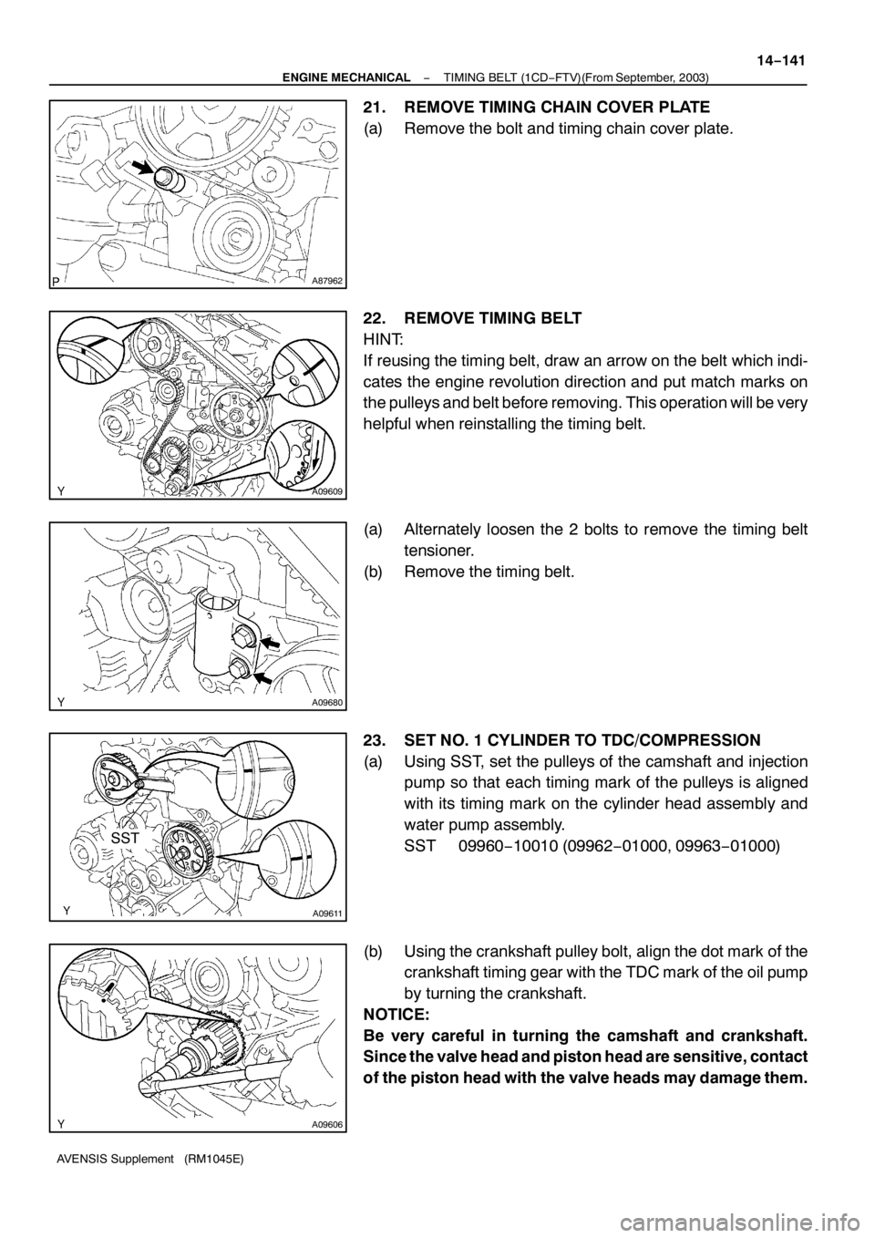
21. REMOVE TIMING CHAIN COVER PLATE
(a) Remove the bolt and timing chain cover plate.
22. REMOVE TIMING BELT
HINT:
If reusing the timing belt, draw an arrow on the belt which indi-
cates the engine revolution direction and put match marks on
the pulleys and belt before removing. This operation will be very
helpful when reinstalling the timing belt.
(a) Alternately loosen the 2 bolts to remove the timing belt
tensioner.
(b) Remove the timing belt.
23. SET NO. 1 CYLINDER TO TDC/COMPRESSION
(a) Using SST, set the pulleys of the camshaft and injection
pump so that each timing mark of the pulleys is aligned
with its timing mark on the cylinder head assembly and
water pump assembly.
SST 09960−10010 (09962−01000, 09963−01000)
(b) Using the crankshaft pulley bolt, align the dot mark of the
crankshaft timing gear with the TDC mark of the oil pump
by turning the crankshaft.
NOTICE:
Be very careful in turning the camshaft and crankshaft.
Since the valve head and piston head are sensitive, contact
of the piston head with the valve heads may damage them.
Page 4655 of 5135
A61186
SST
A84289
14−11 4−
ENGINE MECHANICAL PARTIAL ENGINE ASSY (1CD −FTV)(From September,
2003)
AVENSIS Supplement (RM1045E)
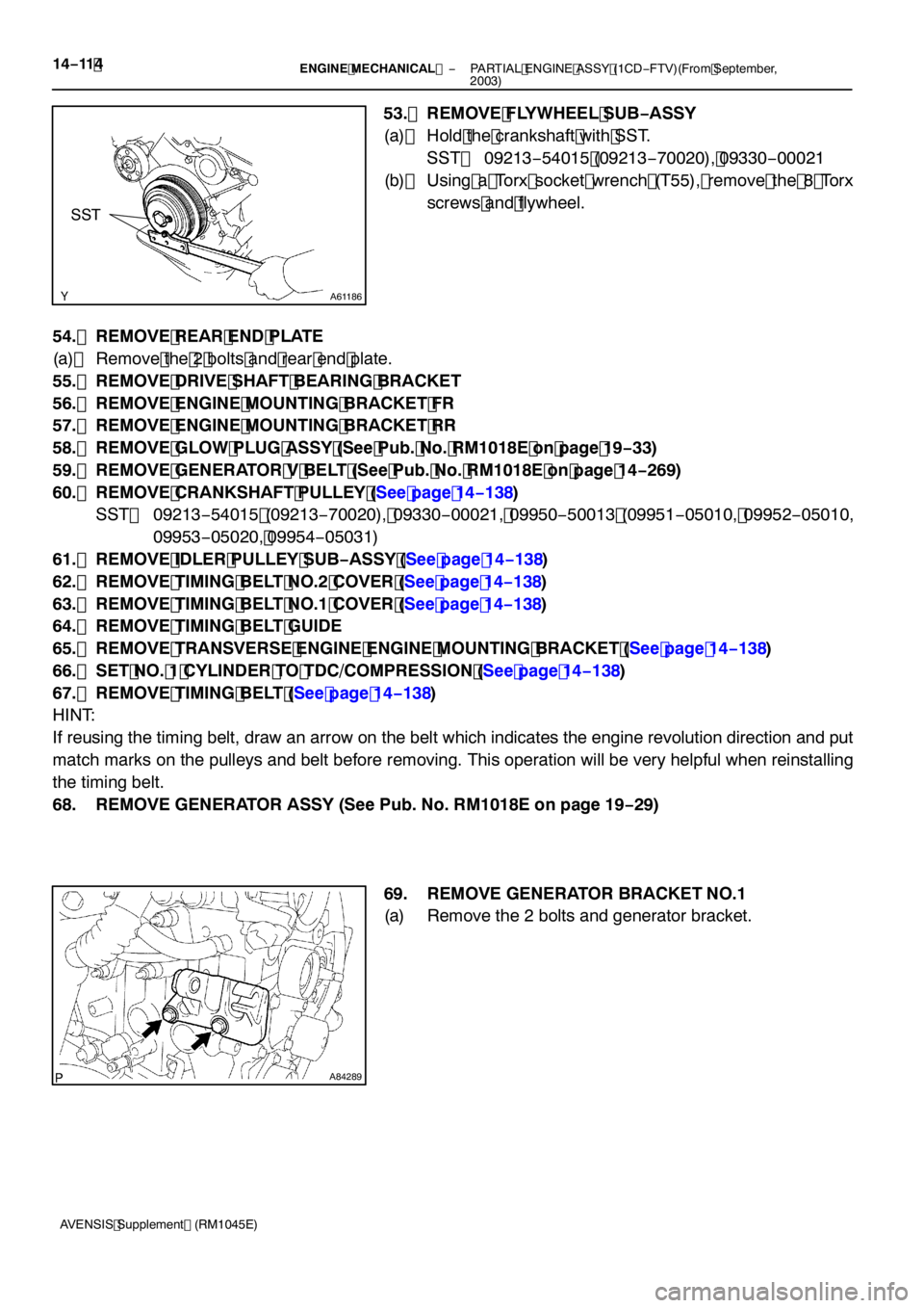
53. REMOVE FLYWHEEL SUB −ASSY
(a) Hold the crankshaft with SST. SST 09213 −54015 (09213 −70020), 09330 −00021
(b) Using a Torx socket wrench (T55), remove the 8 Torx
screws and flywheel.
54. REMOVE REAR END PLATE
(a) Remove the 2 bolts and rear end plate.
55. REMOVE DRIVE SHAFT BEARING BRACKET
56. REMOVE ENGINE MOUNTING BRACKET FR
57. REMOVE ENGINE MOUNTING BRACKET RR
58. REMOVE GLOW PLUG ASSY (See Pub. No. RM1018E on page 19 −33)
59. REMOVE GENERATOR V BELT (See Pub. No. RM1018E on page 14 −269)
60. REMOVE CRANKSHAFT PULLEY (See page 14 −138)
SST 09213 −54015 (09213 −70020), 09330 −00021, 09950 −50013 (09951 −05010, 09952 −05010,
09953 −05020, 09954 −05031)
61. REMOVE IDLER PULLEY SUB −ASSY (See page 14 −138)
62. REMOVE TIMING BELT NO.2 COVER (See page 14 −138)
63. REMOVE TIMING BELT NO.1 COVER (See page 14 −138)
64. REMOVE TIMING BELT GUIDE
65. REMOVE TRANSVERSE ENGINE ENGINE MOUNTING BRACKET (See page 14 −138)
66. SET NO. 1 CYLINDER TO TDC/COMPRESSION (See page 14 −138)
67. REMOVE TIMING BELT (See page 14 −138)
HINT:
If reusing the timing belt, draw an arrow on the belt which indicates the engine revolution direction and put
match marks on the pulleys and belt before removing. This operation will be very helpful when reinstalling
the timing belt.
68. REMOVE GENERATOR ASSY (See Pub. No. RM1018E on page 19 −29)
69. REMOVE GENERATOR BRACKET NO.1
(a) Remove the 2 bolts and generator bracket.
Page 4690 of 5135
141NB−01
−
ENGINE MECHANICAL CYLINDER HEAD GASKET (2AZ −FSE)
14 −79
AVENSIS Supplement (RM1045E)
REPLACEMENT
1. DISCHARGE FUEL SYSTEM PRESSURE (See page 11 −4)
2. REMOVE FRONT WHEEL RH
3. REMOVE RADIATOR SUPPORT OPENING COVER (See page 14 −23)
4. REMOVE ENGINE ROOM COVER SIDE (See page 14 −23)
5. REMOVE ENGINE UNDER COVER LH (See page 14 −23)
6. REMOVE ENGINE UNDER COVER NO.4 RH (See page 14 −23)
7. REMOVE ENGINE UNDER COVER RH (See page 14 −23)
8. DRAIN COOLANT (See page 16 −7)
9. DRAIN ENGINE OIL (See page 17 −6)
10. REMOVE ENGINE COVER SUB −ASSY NO.1 (See page 14 −45)
11. REMOVE FUEL PRESSURE PULSATION DAMPER ASSY
12. SEPARATE FUEL TUBE SUB −ASSY (See page 11 −4)
13. REMOVE FUEL PIPE SUB −ASSY NO.1 (See page 11 −24)
SST 09023 −12900
14. REMOVE FUEL PUMP ASSY (See page 11 −24)
15. REMOVE FAN AND GENERATOR V BELT (See page 14 −5)
SST 09249 −63010
16. REMOVE GENERATOR ASSY (See page 19 −8)
17. REMOVE EXHAUST PIPE ASSY FRONT (See page 15 −2)
18. SEPARATE VANE PUMP ASSY (See page 14 −45)
19. REMOVE IGNITION COIL ASSY (See page 14 −45)
20. SEPARATE RETURN TUBE SUB −ASSY (See page 14 −45)
21. SEPARATE COOLER REFRIGERANT SUCTION HOSE NO.1 (LHD STEERING POSITION TYPE) (See page 14 −45)
22. REMOVE VANE PUMP OIL RESERVOIR ASSY (See page 14 −45)
23. REMOVE OIL RESERVOIR BRACKET NO.1 (See page 14 −45)
24. SEPARATE ENGINE WIRE (See page 14 −23)
25. REMOVE COOLER BRACKET (LHD STEERING POSITION TYPE) (See page 14 −45)
26. REMOVE ENGINE SERVICE COVER BRACKET RH (RHD STEERING POSITION TYPE)
(See page 14 −45)
27. REMOVE CYLINDER HEAD COVER SUB −ASSY (See page 14 −45)
28. SET NO. 1 CYLINDER TO TDC/COMPRESSION (See page 14 −45)
29. REMOVE ENGINE MOUNTING BRACKET NO.2 RH (See page 14 −45)
30. REMOVE TRANSVERSE ENGINE ENGINE MOUNTING INSULATOR (See page 14 −45)
31. REMOVE CRANKSHAFT PULLEY (See page 14 −45)
SST 09213 −54015 (91651 −60855), 09330 −00021, 09950 −50013 (09951 −05010, 09952 −05010,
09953 −05020, 09954 −05021)
32. REMOVE CHAIN TENSIONER ASSY NO.1 (See page 14 −45)
33. REMOVE CRANKSHAFT POSITION SENSOR (See page 14 −45)
34. REMOVE OIL PAN SUB −ASSY (See page 14 −45)
SST 09032 −00100
35. REMOVE V −RIBBED BELT TENSIONER ASSY (See page 14 −45)
36. REMOVE TIMING CHAIN OR BELT COVER SUB −ASSY (See page 14 −45)
37. REMOVE CRANKSHAFT POSITION SENSOR PLATE NO.1 (See page 14 −45)
38. REMOVE CHAIN TENSIONER SLIPPER (See page 14 −45)
39. REMOVE CHAIN VIBRATION DAMPER NO.1 (See page 14 −45)
40. REMOVE TIMING CHAIN GUIDE (See page 14 −45)
41. REMOVE CHAIN SUB −ASSY (See page 14 −45)
Page 4761 of 5135
1509W−02
A85748
30 (302, 22)43 (440, 32)zGasketzGasket
Floor Panel Brace Front Exhaust Pipe Assy Front
Compression Spring
N·m (kgf·cm, ft·lbf)
: Specified torque
zNon−reusable part
43 (440, 32)
Compression Spring
Exhaust Pipe Assy Tail
Air−fuel Ratio Sensor
43 (440, 32)
44 (449, 33)
− EXHAUSTEXHAUST PIPE ASSY (1CD−FTV)(From September,
2003)15−5
AVENSIS Supplement (RM1045E)
EXHAUST PIPE ASSY (1CD−FTV)(From September, 2003)
COMPONENTS
Page 4793 of 5135
A94209
A94210
Coil Joint Oil Ring Ends
A94208
Upward
No. 1
No. 2
Code Mark (T2)Painted Mark
A94211
Front30_
No. 1 Compression
and Oil Ring
No. 2 Compression
30_
− ENGINE MECHANICALCYLINDER BLOCK ASSY (2AZ−FSE)
14−69
2AZ−FSE ENGINE REPAIR MANUAL (RM1083E)
32. INSTALL PISTON RING SET
(a) Install the coil by hand.
(b) Using a piston ring expander, install the oil ring.
HINT:
Face the end gap of the oil ring in the opposite direction of coil
joint.
(c) Using a piston ring expander, install the 2 compression
rings with the painted mark as shown in the illustration.
NOTICE:
Install the compression ring No. 2 with the code mark (T2)
facing upward.
(d) Position the piston rings so that the ring ends are as
shown in the illustration.
Page 4977 of 5135
A78423
20V
/Division Injector Signal Waveform
20V
/Division
GND
100 msec./Division (Idling)(Magnification)
GND
1 msec./Division (Idling)
Injection Duration
– DIAGNOSTICSSFI SYSTEM (1ZZ–FE/3ZZ–FE)(From February, 2004)
05–119
AVENSIS REPAIR MANUAL SUPPLEMENT
(RM1098E)DTC No.
DTC Detection ConditionTrouble Area
P0300Misfiring of random cylinders is detected
�Open or short in engine wire harness
�Connector connection
�Vacuum hose connection
�Ignition system
�Injector
�Fuel pressure
�Mass air flow meter
�Engine coolant temperature sensor
�Compression pressure
�Valve clearance
�Valve timing
�PCV hose connection
�PCV hose
�ECM
P0301
P0302
Misfiring of each cylinder is detected
�Open or short in engine wire harness
�Connector connection
�Vacuum hose connection
�Ignition system
�Injector
�Fuel pressure
�Mass air flow meter
P0303
P0304Misfiring of each cylinder is detected�Engine coolant temperature sensor
�Compression pressure
�Valve clearance
�Valve timing
�PCV hose connection
�PCV hose
�ECM
HINT:
When the DTCs for misfiring cylinders are recorded repeatedly but no random misfire DTC is recorded, it
indicates that the misfires have been set and recorded at different times.
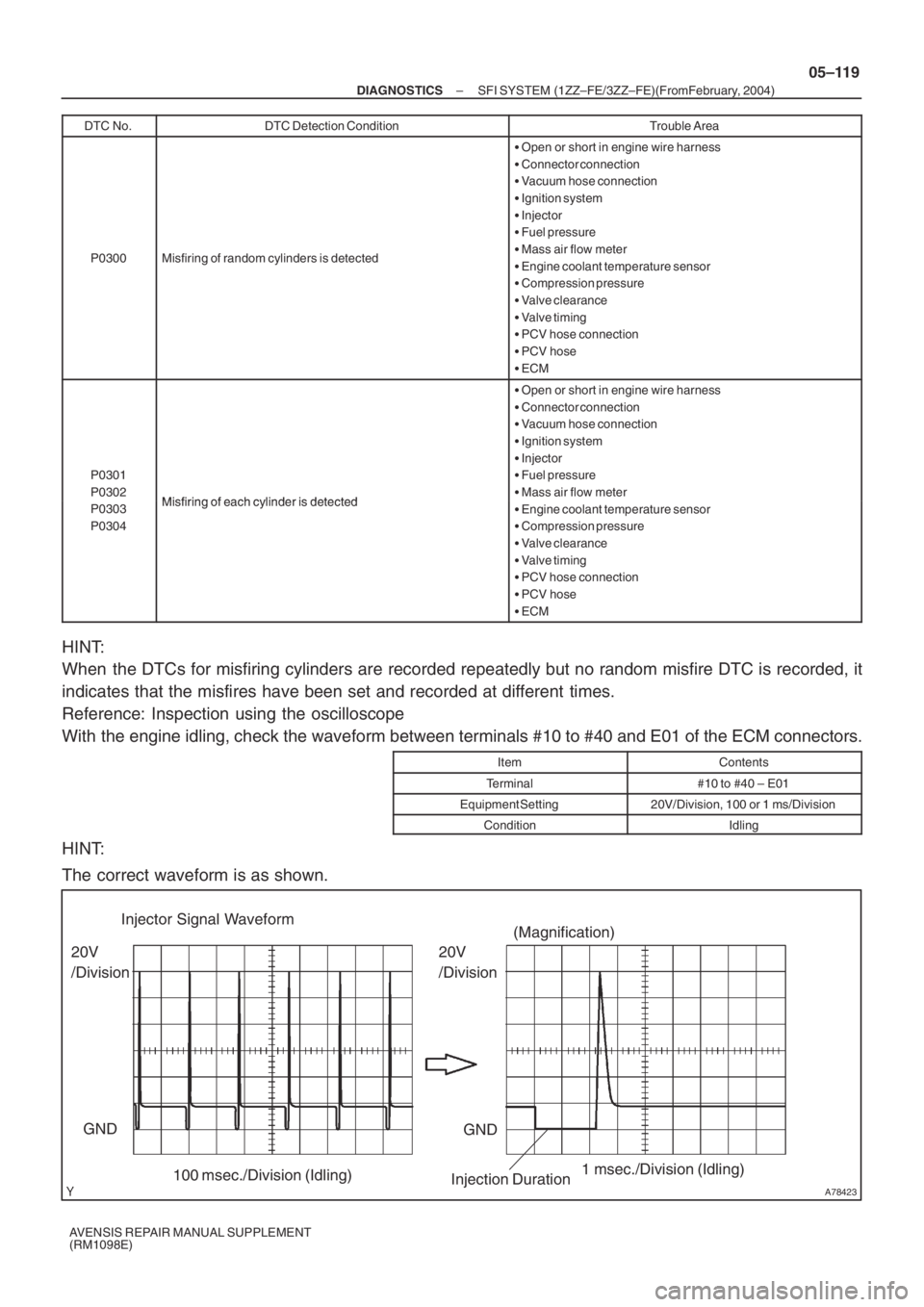
Reference: Inspection using the oscilloscope
With the engine idling, check the waveform between terminals #10 to #40 and E01 of the ECM connectors.
ItemContents
Terminal#10 to #40 – E01
Equipment Setting20V/Division, 100 or 1 ms/Division
ConditionIdling
HINT:
The correct waveform is as shown.
Page 5054 of 5135
A01045
A64005
A64856
A62185
Mark
Mark
Mark
Timing Chain
Cover Surface
Timing
Notch
– ENGINE MECHANICALCYLINDER HEAD GASKET (1ZZ–FE/3ZZ–FE)(From
February, 2004)14–35
AVENSIS REPAIR MANUAL SUPPLEMENT
(RM1098E)
31. REMOVE ENGINE MOUNTING INSULATOR
SUB–ASSY RH
(a) Place a wooden block on a jack underneath the engine.
Remove the 4 bolts and 2 nuts, then detach the engine
mounting insulator RH.
32. REMOVE CYLINDER HEAD COVER SUB–ASSY
(a) Remove the 9 bolts, 2 seal washers, 2 nuts and 3 clamp
brackets.
(b) Remove the cylinder head cover.
33. SET NO. 1 CYLINDER TO TDC/COMPRESSION
(a) Turn the crankshaft pulley until the timing notch is aligned
with the timing mark ”0” of the timing chain cover.
(b) Check that the point marks of the camshaft timing sprock-
et and VVT timing sprocket are in a straight line on the tim-
ing chain cover surface as shown in the illustration.
HINT:
If not, turn the crankshaft 1 revolution (360�) to align the marks
as above.
Page 5058 of 5135
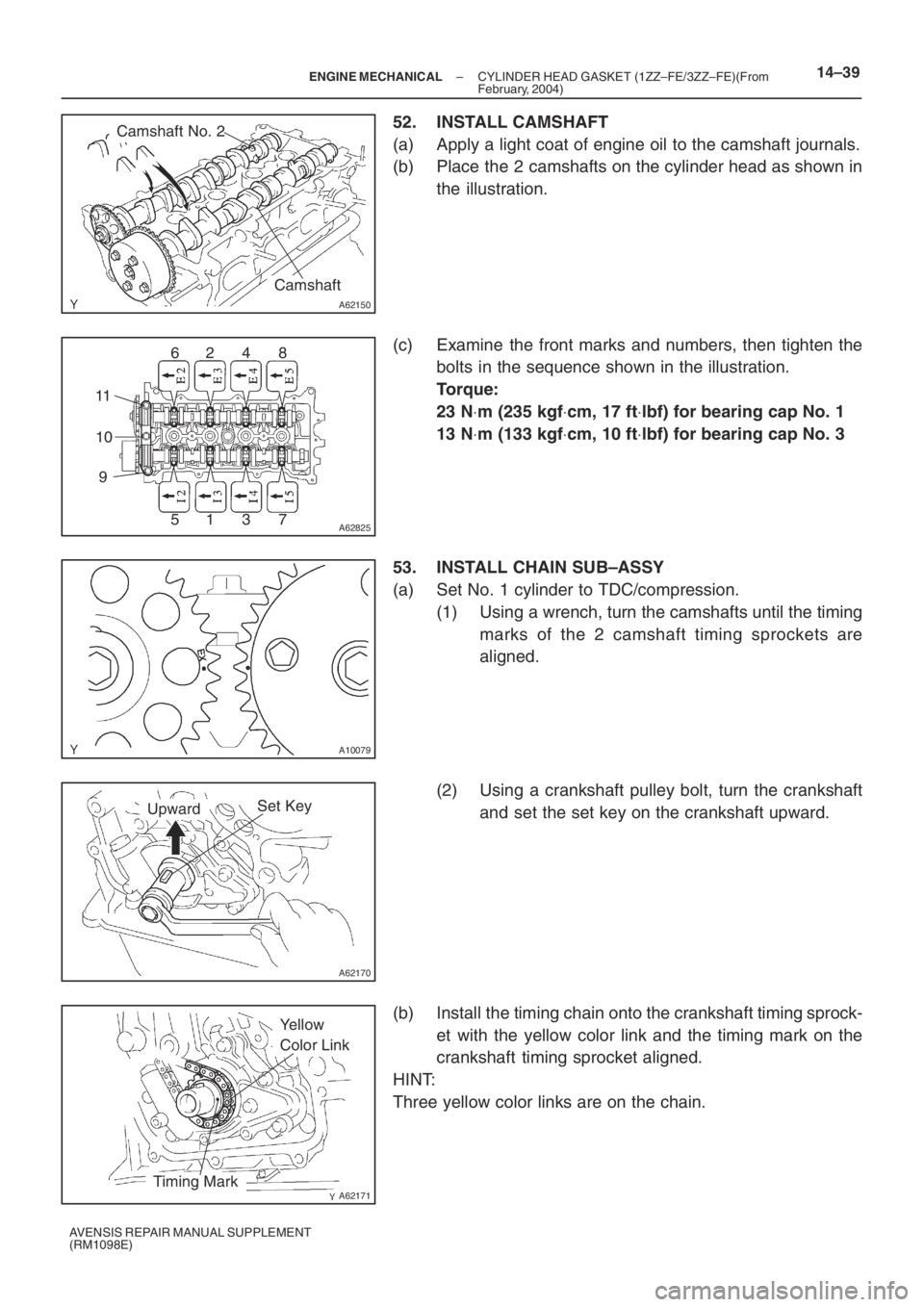
A62150
Camshaft No. 2
Camshaft
A62825
62 4 8
51 3 7 11
10
9
A10079
A62170
Set KeyUpward
A62171
Yellow
Color Link
Timing Mark
– ENGINE MECHANICALCYLINDER HEAD GASKET (1ZZ–FE/3ZZ–FE)(From
February, 2004)14–39
AVENSIS REPAIR MANUAL SUPPLEMENT
(RM1098E)
52. INSTALL CAMSHAFT
(a) Apply a light coat of engine oil to the camshaft journals.
(b) Place the 2 camshafts on the cylinder head as shown in
the illustration.
(c) Examine the front marks and numbers, then tighten the
bolts in the sequence shown in the illustration.
Torque:
23 N⋅m (235 kgf⋅cm, 17 ft⋅lbf) for bearing cap No. 1
13 N⋅m (133 kgf⋅cm, 10 ft⋅lbf) for bearing cap No. 3
53. INSTALL CHAIN SUB–ASSY
(a) Set No. 1 cylinder to TDC/compression.
(1) Using a wrench, turn the camshafts until the timing
marks of the 2 camshaft timing sprockets are
aligned.
(2) Using a crankshaft pulley bolt, turn the crankshaft
and set the set key on the crankshaft upward.
(b) Install the timing chain onto the crankshaft timing sprock-
et with the yellow color link and the timing mark on the
crankshaft timing sprocket aligned.
HINT:
Three yellow color links are on the chain.