Page 1915 of 5135

11±74
±
FUEL INJECTION OR SUPPLY PUMP ASSY(1CD±FTV)
AVENSIS REPAIR MANUAL (RM1018E)
46.INSTALL FUEL INLET PIPE SUB±ASSY
NOTICE:
�In case of having the injection pum")
A79149
SST
30 cm
(11.81 in.)
11±74
±
FUEL INJECTION OR SUPPLY PUMP ASSY(1CD±FTV)
AVENSIS REPAIR MANUAL (RM1018E)
46.INSTALL FUEL INLET PIPE SUB±ASSY
NOTICE:
�In case of having the injection pump replaced, must
replace the fuel inlet pipe, too.
�When assembling the pipe, perform the operation
with the engine cold under room temperature.
(a)Temporarily install the fuel inlet pipe.
(b)Using SST, tighten the nut of the fuel inlet pipe to the com-
mon rail side.
SST09023±12700
Torque:
42 N�m (428 kgf �cm, 31 ft �lbf) for a used pipe using SST
46 N �m (469 kgf �cm, 34 ft �lbf) for a used pipe not using
SST
31 N �m (316 kgf �cm, 23 ft �lbf) for a new pipe using SST
34 N �m (347 kgf �cm, 25 ft �lbf) for a new pipe not using
SST
HINT:
�Use a torque wrench with a fulcrum length of 30 cm
(11.81 in.)
�Check if the used pipe has deflection or is installed prop-
erly after inlet pipe is reassembled. If there is deflection
or if it can not be installed properly, replace the used pipe
with a new pipe.
(c)Using SST, tighten the nut of the fuel inlet pipe to the injec-
tion pump side.
SST09023±12700
Torque:
42 N�m (428 kgf �cm, 31 ft �lbf) for a used pipe using SST
46 N �m (469 kgf �cm, 34 ft �lbf) for a used pipe not using
SST
31 N �m (316 kgf �cm, 23 ft �lbf) for a new pipe using SST
34 N �m (347 kgf �cm, 25 ft �lbf) for a new pipe not using
SST
HINT:
�Use a torque wrench with a fulcrum length of 30 cm
(11.81 in.)
�Check if the used pipe has deflection or is installed prop-
erly after inlet pipe is reassembled. If there is deflection
or if it can not be installed properly, replace the used pipe
with a new pipe.
47.SET NO. 1 CYLINDER TO TDC/COMPRESSION(See page 14±307) SST 09960±10010 (09962±01000, 09963±01000)
48.INSTALL TIMING BELT(See page 14±307)
49.CHECK VALVE TIMING(See page 14±307)
50.INSTALL TIMING CHAIN COVER PLATE(See page 14±307)
51. INSTALL TRANSVERSE ENGINE ENGINE MOUNTING BRACKET Torque:
37 N�m (375 kgf �cm, 27 ft �lbf) for 14mm head bolt
64 N �m (650 kgf �cm, 47 ft �lbf) for 17mm head bolt
Page 1957 of 5135
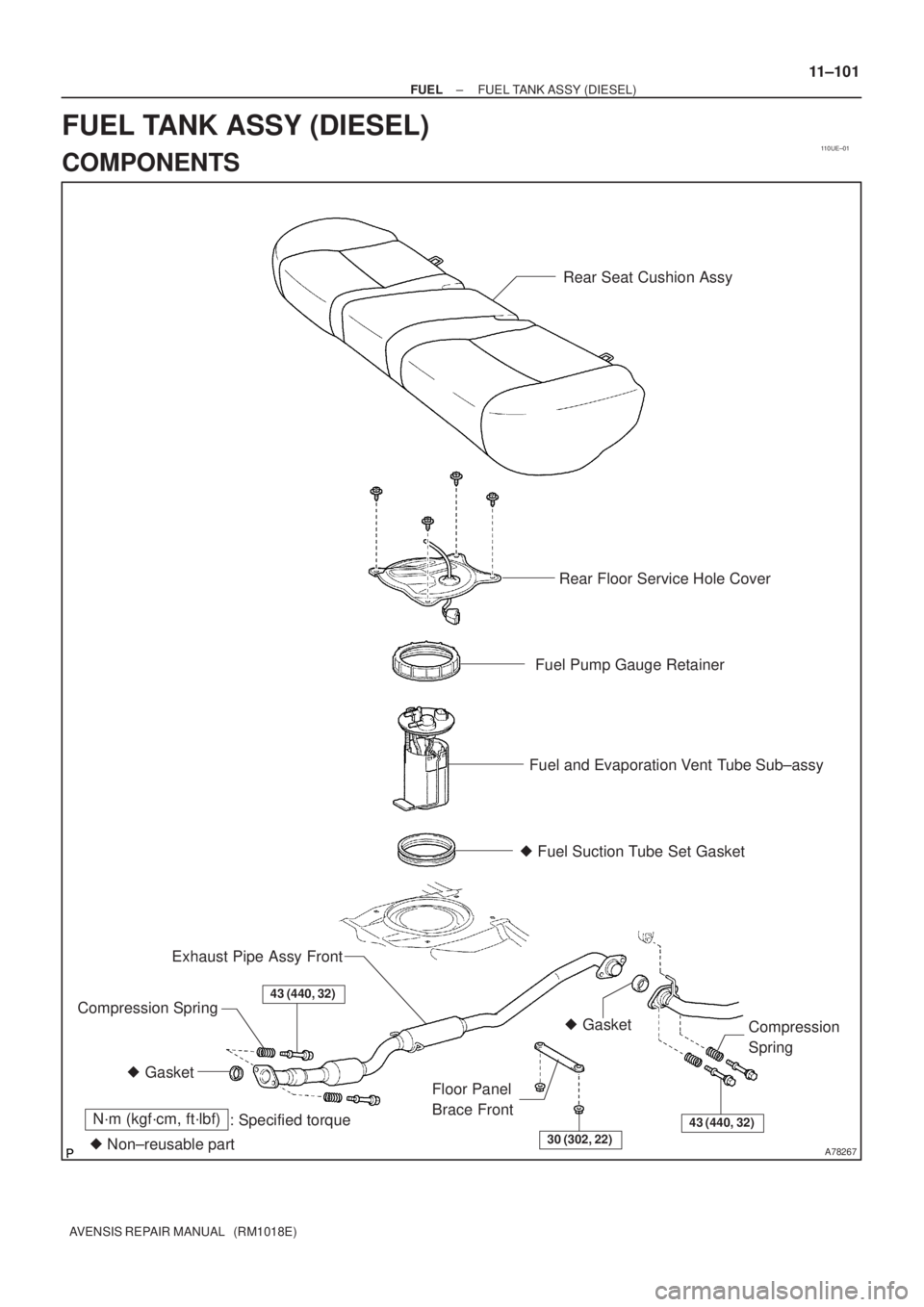
110UE±01
A78267
Rear Seat Cushion Assy
Rear Floor Service Hole Cover
Fuel Pump Gauge Retainer
Fuel and Evaporation Vent Tube Sub±assy
N´m (kgf´cm, ft´lbf)
: Specified torque
� Non±reusable part� Fuel Suction Tube Set Gasket
� Gasket� Gasket Exhaust Pipe Assy Front
Compression Spring
Floor Panel
Brace FrontCompression
Spring43 (440, 32)
30 (302, 22)
43 (440, 32)
± FUELFUEL TANK ASSY (DIESEL)
11±101
AVENSIS REPAIR MANUAL (RM1018E)
FUEL TANK ASSY (DIESEL)
COMPONENTS
Page 1966 of 5135

11±99
AVENSIS REPAIR MANUAL (RM1018E)
30. CONNECT FUEL TANK MAIN TUBE SUB±ASSY
(a) Push in the fuel tube c")
A81618
Push
2
1
Retainer
A77857
A78440
New Gasket
A77857
± FUELFUEL TANK ASSY (GASOLINE)
11±99
AVENSIS REPAIR MANUAL (RM1018E)
30. CONNECT FUEL TANK MAIN TUBE SUB±ASSY
(a) Push in the fuel tube connector to the pipe until it makes
ºclickº sound, and then push up the retainer to the claws
lock.
NOTICE:
�Check if there is any damage or foreign objects on the
connected part.
�After connecting, check if the fuel tube connector and
the pipe are securely connected by pulling on them.
31. CONNECT FUEL TANK RETURN TUBE (1AZ±FSE
ENGINE TYPE)
32. CONNECT FUEL TANK TO FILLER PIPE HOSE
33. CONNECT BREATHER TUBE FUEL HOSE
34. INSTALL PARKING BRAKE CABLE ASSY NO.3
Torque: 5.0 N�m (51 kgf�cm, 44 in.�lbf)
35. INSTALL PARKING BRAKE CABLE ASSY NO.2
Torque: 5.0 N�m (51 kgf�cm, 44 in.�lbf)
36. INSTALL FUEL TANK PROTECTOR NO.1
Torque: 5.4 N�m (55 kgf�cm, 48 in.�lbf)
37. INSTALL EXHAUST PIPE ASSY CENTER
(1ZZ±FE/3ZZ±FE ENGINE TYPE)
(a) Compression spring inspection
(1) Using vernier calipers, measure the free length of
the compression spring.
Minimum length:
41.5 mm (1.634 in.) for front x manifold
38.5 mm (1.516 in.) for front x tail
If the free length is less than minimum, replace the compression
spring.
(b) Install each new gasket to the exhaust manifold and the
exhaust pipe front as shown in the illustration.
(c) Install the exhaust pipe front to the 2 exhaust pipe sup-
ports
(d) Tighten the 4 compression springs and 4 bolts.
Torque: 43 N�m (440 kgf�cm, 32 ft�lbf)
(e) Install the grommet. (w/o HID Sensor)
(f) Connect the heated oxygen sensor connector.
(g) Install the floor carpet with the 2 clips. (w/o HID Sensor)
38. INSTALL EXHAUST PIPE ASSY CENTER
(1AZ±FE/1AZ±FSE ENGINE TYPE)
(a) Compression spring inspection
(1) Using vernier calipers, measure the free length of
the compression spring.
Minimum length: 38.5 mm (1.516 in.)
If the free length is less than minimum, replace the compression
spring.
Page 1967 of 5135

AVENSIS REPAIR MANUAL (RM1018E)
(b)Install a new gasket to the the exhaust pipe center (ex- haust pipe tail side) as shown in the illustrat")
A78440
New Gasket
11±100
±
FUEL FUEL TANK ASSY(GASOLINE)
AVENSIS REPAIR MANUAL (RM1018E)
(b)Install a new gasket to the the exhaust pipe center (ex- haust pipe tail side) as shown in the illustration.
(c)Install a new gasket (exhaust pipe front side) and the ex-
haust pipe center to the 2 exhaust pipe supports.
(d)Tighten the 2 compression springs and 4 bolts. Torque: 43 N �m (440 kgf �cm, 32 ft �lbf)
39.ADD FUEL
40.INSTALL FUEL SUCTION W/PUMP & GAGE TUBE ASSY (See page 11±85) SST 09808±14010
41.CONNECT FUEL EVAPORATION TUBE SUB±ASSY NO.2 (See page 11±85)
42.CONNECT FUEL TANK MAIN TUBE SUB±ASSY (See page 11±85)
43.CONNECT FUEL TANK RETURN TUBE (1AZ±FSE ENGINE TYPE) (See page 11±85)
44. CHECK FOR FUEL LEAKS
HINT:
�1ZZ±FE/3ZZ±FE: 11±5
�1AZ±FE: 11±19
�1AZ±FSE: 11±33
45. CHECK FOR EXHAUST GAS LEAKS
46.INSTALL FLOOR PANEL BRACE FRONT (See page 15±2)
47. INSTALL REAR FLOOR SERVICE HOLE COVER
48.INSTALL REAR SEAT CUSHION ASSY (SEAT FIXED TYPE) (See page 72±32)
49. INSTALL FRONT FLOOR FOOTREST (W/O HID SENSOR)
Page 1973 of 5135

14±7
AVENSIS REPAIR MANUAL (RM1018E)
6. DISCONNECT VENTILA")
A64058
A64856
A62185
Mark
Mark
Mark
Timing Chain
Cover Surface
Timing
Notch
A01131
± ENGINE MECHANICALVALVE CLEARANCE (1ZZ±FE/3ZZ±FE)
14±7
AVENSIS REPAIR MANUAL (RM1018E)
6. DISCONNECT VENTILATION HOSE NO.2
(a) Disconnect the ventilation hose from the cylinder head
cover.
7. REMOVE CYLINDER HEAD COVER SUB±ASSY
(a) Remove the 9 bolts, 2 seal washers, 2 nuts, 3 clamp
brackets and cylinder head cover.
8. REMOVE ENGINE UNDER COVER SUB±ASSY NO.1
9. REMOVE ENGINE UNDER COVER RH
10. SET NO. 1 CYLINDER TO TDC/COMPRESSION
(a) Turn the crankshaft pulley, and align the timing notch with
timing mark º0º of the timing chain cover.
(b) Check that the point marks of the camshaft timing sprock-
et and VVT timing sprocket are in straight line on the tim-
ing chain cover surface as shown in the illustration.
HINT:
If not, turn the crankshaft 1 revolution (360�) and align the
marks as above.
11. INSPECT VALVE CLEARANCE
(a) Check the valves indicated in the illustration.
(1) Using a feeler gauge, measure the clearance be-
tween the valve lifter and the camshaft.
(2) Record the out±of specification valve clearance
measurements. They will be used later to determine
the required replacement valve lifter.
Valve clearance (Cold):
Intake 0.15 to 0.25 mm (0.0059 to 0.0098 in.)
Exhaust 0.25 to 0.35 mm (0.0098 to 0.0138 in.)
Page 1974 of 5135

AVENSIS REPAIR MANUAL (RM1018E)
(b) Turn the crankshaft 1 revolution (360 �) and set No. 4 cyl-
inder to TDC/c")
A01132
A60622
A01045
A64005
14±8
± ENGINE MECHANICALVALVE CLEARANCE (1ZZ±FE/3ZZ±FE)
AVENSIS REPAIR MANUAL (RM1018E)
(b) Turn the crankshaft 1 revolution (360 �) and set No. 4 cyl-
inder to TDC/compression.
(c) Check the valves indicated in the illustration.
(1) Using a feeler gauge, measure the clearance be-
tween the valve lifter and camshaft.
(2) Record the out±of specification valve clearance
measurements. They will be used later to determine
the required replacement valve lifter.
Valve clearance (Cold):
Intake 0.15 to 0.25 mm (0.0059 to 0.0098 in.)
Exhaust 0.25 to 0.35 mm (0.0098 to 0.0138 in.)
12. REMOVE FAN AND GENERATOR V BELT
(a) Turn the V±ribbed belt tensioner clockwise slowly and
loosen it. Then, remove the fan and generator V belt and
put back the V±ribbed belt tensioner carefully.
13. REMOVE ENGINE MOUNTING INSULATOR
SUB±ASSY RH
(a) Place a wooden block on a jack underneath the engine.
Remove the 4 bolts and 2 nuts and detach the engine
mounting insulator RH.
Page 1988 of 5135

14±3
AVENSIS REPAIR MANUAL (RM1018E)
(3) While cranking the engine, measure the compres-
sion pressure.
Compression pressure
�
1,300 kPa (13.3 kgf�cm
2")
± ENGINE MECHANICALENGINE (1ZZ±FE/3ZZ±FE)
14±3
AVENSIS REPAIR MANUAL (RM1018E)
(3) While cranking the engine, measure the compres-
sion pressure.
Compression pressure
�
1,300 kPa (13.3 kgf�cm
2, 189 psi)
Minimum pressure: 1,000 kPa (10.2 kgf�cm
2, 145 psi)
Difference between each cylinder:
100 kPa (1.0 kgf�cm
2, 14 psi)
NOTICE:
�Always use a fully charged battery to obtain engine
speed of 250 rpm or more.
�Check other cylinder's compression pressure in the
same way.
�This measurement must be done in as short a time as
possible.
(4) If the cylinder compression in one or more cylinders
is low, pour a small amount of engine oil into the cyl-
inder through the spark plug hole and repeat steps
(1) through (3) for the cylinders that have low com-
pression.
HINT:
�If adding oil helps increase the compression, the piston
rings and/or cylinder bore may be worn or damaged.
�If pressure stays low, a valve may be sticking or seating
improperly, or there may be leakage past the gasket.
10. INSPECT CO/HC
(a) Start the engine.
(b) Run the engine at 2,500 rpm for approximately 180 seconds.
(c) Insert CO/HC meter testing probe at least 40 cm (1.3 ft) into the tailpipe during idling.
(d) Check CO/HC concentration at idle.
Idle CO concentration: 0 to 0.5 %
Idle HC concentration: Applicable local regulation
If the CO/HC concentration does not conform to specifications, perform troubleshooting in the order given
below.
�Check heated oxygen sensor operation.
�See the table below for possible causes, and then inspect and repair the applicable causes if
necessary.
Page 2014 of 5135

AVENSIS REPAIR MANUAL (RM1018E)
12. SET NO.")
A62185
Mark
Mark
Mark
Timing Chain
Cover Surface
Timing
Notch
A11858
A62186
Paint Mark
A62178
Push 14±66
± ENGINE MECHANICALCAMSHAFT (1ZZ±FE/3ZZ±FE)
AVENSIS REPAIR MANUAL (RM1018E)
12. SET NO. 1 CYLINDER TO TDC/COMPRESSION
(a) Turn the crankshaft pulley to align the timing notch with
timing mark º0º of the timing chain cover.
(b) Check that the point marks of the camshaft timing sprock-
et and VVT timing sprocket are in straight line on the tim-
ing chain cover surface as shown in the illustration.
HINT:
If not, turn the crankshaft 1 revolution (360�) and align the
marks as above.
13. REMOVE V±RIBBED BELT TENSIONER ASSY
(a) Remove the bolt and nut, then remove the V±ribbed belt
tensioner.
HINT:
Jack up and down to remove the bolt.
14. REMOVE CAMSHAFT
NOTICE:
Do not revolve the crankshaft without the chain tensioner.
(a) Set the No. 1 cylinder to the TDC/compression.
(b) Place match marks on the timing chain and the camshaft
timing sprockets.
(c) Remove the 2 nuts and the chain tensioner.