Page 4763 of 5135

SST
A09582
B07973
Cut PositionPry
SST
A08528
SST
A09583
Angle
SensorInward
14
−178−
ENGINE MECHANICAL CRANKSHAFT SEAL (1CD−FTV)(From September,
2003)
AVENSIS Supplement (RM1045E)
21. SET NO. 1 CYLINDER TO TDC/COMPRESSION (See page 14 −138)
22. REMOVE TIMING CHAIN COVER PLATE (See page 14 −138)
23. REMOVE TIMING BELT (See page 14 −138)
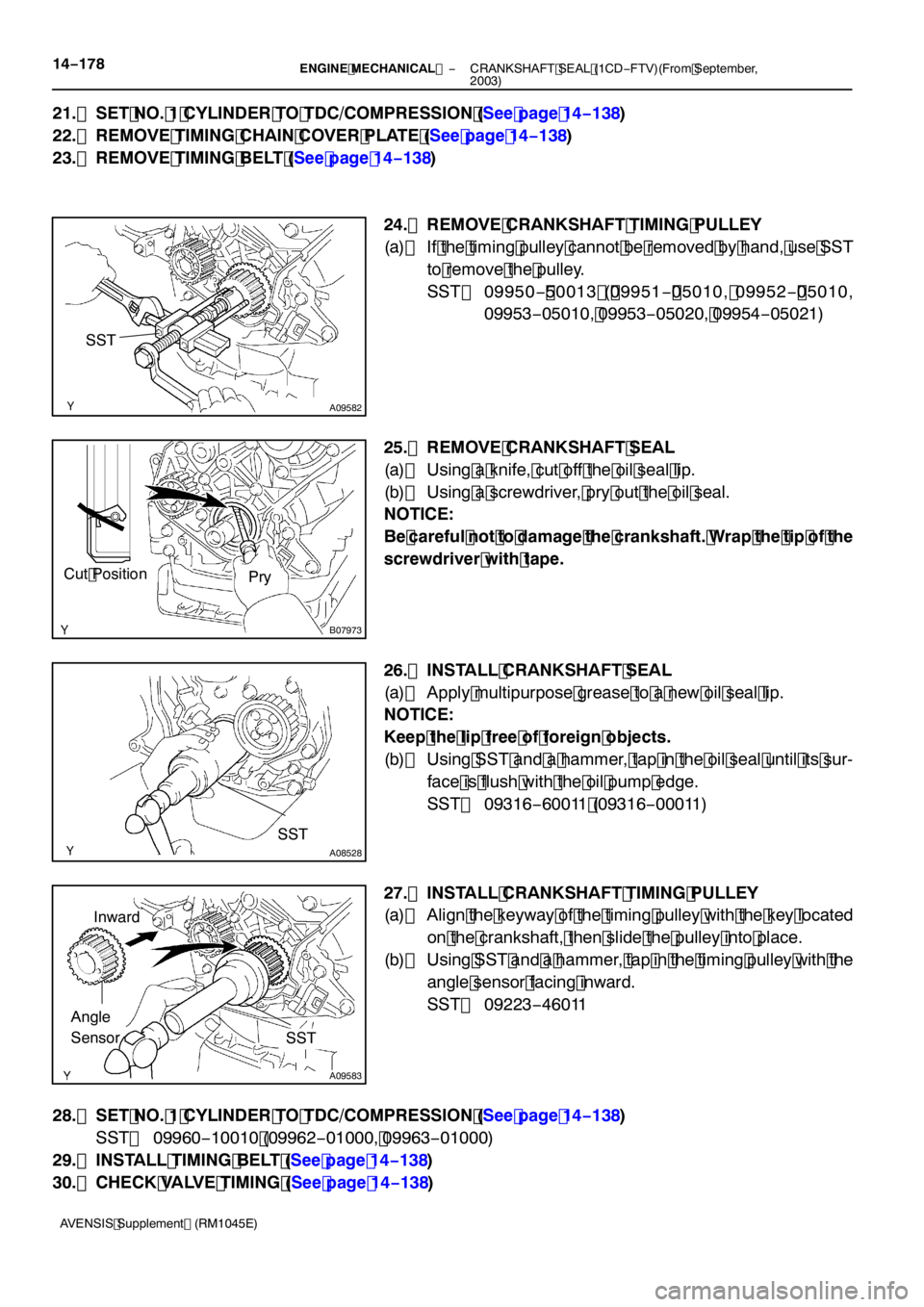
24. REMOVE CRANKSHAFT TIMING PULLEY
(a) If the timing pulley cannot be removed by hand, use SST to remove the pulley.
SST 09950 − 50013 ( 09951 − 05010, 09952 − 05010,
09953 −05010, 09953 −05020, 09954 −05021)
25. REMOVE CRANKSHAFT SEAL
(a) Using a knife, cut off the oil seal lip.
(b) Using a screwdriver, pry out the oil seal.
NOTICE:
Be careful not to damage the crankshaft. Wrap the tip of the
screwdriver with tape.
26. INSTALL CRANKSHAFT SEAL
(a) Apply multipurpose grease to a new oil seal lip.
NOTICE:
Keep the lip free of foreign objects.
(b) Using SST and a hammer, tap in the oil seal until its sur- face is flush with the oil pump edge.
SST 09316 −60011 (09316 −00011)
27. INSTALL CRANKSHAFT TIMING PULLEY
(a) Align the keyway of the timing pulley with the key located on the crankshaft, then slide the pulley into place.
(b) Using SST and a hammer, tap in the timing pulley with the
angle sensor facing inward.
SST 09223 −46011
28. SET NO. 1 CYLINDER TO TDC/COMPRESSION (See page 14 −138)
SST 09960 −10010 (09962 −01000, 09963 −01000)
29. INSTALL TIMING BELT (See page 14 −138)
30. CHECK VALVE TIMING (See page 14 −138)
Page 4764 of 5135

−
ENGINE MECHANICAL CRANKSHAFT SEAL (1CD−FTV)(From September,
2003)14 −179
AVENSIS Supplement (RM1045E)
31. INSTALL TIMING CHAIN COVER PLATE (See page 14 −138)
32. INSTALL TRANSVERSE ENGINE ENGINE MOUNTING BRACKET (See page 14 −138)
33. INSTALL TIMING BELT GUIDE (See page 14 −138)
34. INSTALL TIMING BELT NO.1 COVER (See page 14 −138)
35. INSTALL TIMING BELT NO.2 COVER (See page 14 −138)
36. INSTALL IDLER PULLEY SUB −ASSY (See page 14 −138)
37. INSTALL CRANKSHAFT PULLEY (See page 14 −138 )
SST 09213 −54015 (09213 −70020), 09330 −00021
38. INSTALL ENGINE MOUNTING INSULATOR SUB −ASSY RH (See page 14 −138)
39. INSTALL POWER STEERING IDLE PULLEY BRACKET (See page 14 −108)
40. ADJUST V (COOLER COMPRESSOR TO CRANKSHAFT PULLEY) BELT NO.1 (See Pub. No. RM1018E on page 14 −269)
41. INSTALL INJECTOR DRIVER (See page 14 −108)
42. INSTALL ENGINE COVER NO.1 (See page 14 −90)
43. INSTALL FRONT WHEEL RH
Torque: 103 N �m (1,050 kgf �cm, 76 ft �lbf)
44. ADD ENGINE OIL
45. CHECK FOR ENGINE OIL LEAKS
Page 4770 of 5135

40189−01
D25831
SST
D25832
SST
D25833
SST
40 −24
−
AUTOMATIC TRANSMISSION / TRANS FRONT DIFFERENTIAL OIL SEAL (U151E)
AVENSIS Supplement (RM1045E)
FRONT DIFFERENTIAL OIL SEAL (U 151E)
REPLACEMENT
1. REMOVE FRONT WHEELS
2. REMOVE ENGINE UNDER COVER RH
3. REMOVE ENGINE UNDER COVER LH
4. DRAIN AUTOMATIC TRANSAXLE FLUID
(a) Remove the drain plug and gasket, and drain ATF.
(b) Install a new gasket and the drain plug. Torque: 47 N �m (480 kgf �cm, 35 ft �lbf)
5. REMOVE FRONT DRIVE SHAFT ASSY RH (SEE PAGE 30 −4)
6. REMOVE FRONT DRIVE SHAFT ASSY LH (SEE PAGE 30 −4)
7. REMOVE TRANSAXLE HOUSING OIL SEAL
(a) Using SST, pull out the oil seal. SST 09308 −00010
8. REMOVE DIFFERENTIAL SIDE BEARING RETAINER OIL SEAL
(a) Using SST, pull out the oil seal.
SST 09308 −00010
9. INSTALL TRANSAXLE HOUSING OIL SEAL
(a) Using SST and a hammer, drive in a new oil seal. SST 09316 −60011 (09316 −00011)
Oil seal drive in depth:
0 �á 0.5 mm (0 �á0.020 in.)
(b) Coat the lip of the oil seal with MP grease.
Page 4771 of 5135
D25834
SST
−
AUTOMATIC TRANSMISSION / TRANS FRONT DIFFERENTIAL OIL SEAL (U151E)
40−25
AVENSIS Supplement (RM1045E)
10. INSTALL DIFFERENTIAL SIDE BEARING RETAINER
OIL SEAL
(a) Using SST and a hammer, drive in a new oil seal. SST 09649 −17010, 09950 −70010 (09951 −07150)
Oil seal drive in depth:
0 �á 0.5 mm (0 �á 0.020 in.)
(b) Coat the lip of the oil seal with MP grease.
11 . INSTALL FRONT DRIVE SHAFT ASSY LH (SEE PAGE 30 −4)
1 2. INSTALL FRONT DRIVE SHAFT ASSY RH (SEE PAGE 30 −4)
1 3. INSTALL FRONT WHEELS
Torque: 103 N �m( 1,050 kgf �cm, 76 ft �lbf)
1 4. ADD AUTOMATIC TRANSAXLE FLUID (SEE PUB. NO. RM 1018E, PAGE40 −2)
1 5. INSPECT AUTOMATIC TRANSAXLE FLUID (SEE PUB. NO. RM 1018E, PAGE40 −2)
1 6. CHECK ABS SPEED SENSOR SIGNAL
(a) ABS WITH EBD & BA &TRAC & VSC SYSTEM (SEE PUB, NO. RM1018E, PAGE 5 −756)
Page 4782 of 5135

A36647
A13478
A01178
80 to 90_C
A01179
A36645
14−58
− ENGINE MECHANICALCYLINDER BLOCK ASSY (2AZ−FSE)
2AZ−FSE ENGINE REPAIR MANUAL (RM1083E)
5. REMOVE PISTON RING SET
(a) Using a piston ring expander, remove the 2 compression
rings.
(b) Remove the 2 side rails and oil ring by hand.
6. REMOVE PISTON PIN HOLE SNAP RING
(a) Using a small screwdriver, pry out the 2 snap rings.
7. REMOVE PISTON
(a) Gradually heat the piston to approximately 80 to 90_C
(176 to 194_F).
(b) Using a plastic−faced hammer and brass bar, lightly tap
out the piston pin and remove the connecting rod.
HINT:
SThe piston and pin are a matched set.
SArrange the pistons, pins, rings, connecting rods and
bearings in the correct order.
8. INSPECT CRANKSHAFT THRUST CLEARANCE
(a) Using a dial indicator, measure the thrust clearance while
prying the crankshaft back and forth with a screwdriver.
Standard thrust clearance:
0.040 to 0.240 mm (0.0016 to 0.0094 in.)
Maximum thrust clearance: 0.30 mm (0.0118 in.)
If the thrust clearance is greater than the maximum, replace the
thrust washers as a set.
Thrust washer thickness:
1.930 to 1.980 mm (0.0760 to 0.0780 in.)
Page 4836 of 5135
400H2−02
D26426
D26427
40−84
− AUTOMATIC TRANSMISSION / TRANSDIRECT CLUTCH ASSY (U151E/U151F)
U151E, U151F A/T REPAIR MANUAL (RM1021U)
DIRECT CLUTCH ASSY (U151E/U151F)
OVERHAUL
1. INSPECT PACK CLEARANCE OF REVERSE CLUTCH
(a) Install the intermediate shaft and needle roller bearing on
the transaxle rear cover .
(b) Using a dial indicator, measure the reverse clutch pack
clearance while applying and releasing compressed air
(392 kPa, 4.0 kgf/cm
2, 57 psi).
Pack clearance:0.60−0.82 mm (0.02362−0.03228 in.)
If the pack clearance is not within standard, inspect the discs,
plates and flange.
2. INSPECT PACK CLEARANCE OF DIRECT CLUTCH &
OVERDRIVE CLUTCH
(a) Using a dial indicator, measure the direct clutch & over-
drive clutch pack clearance while applying and releasing
compressed air (392 kPa, 4.0 kgf/cm
2, 57 psi).
Pack clearance:0.61−0.83 mm (0.02401−0.03268 in.)
If the pack clearance is not within standard, inspect the discs,
plates and flange.
Page 4837 of 5135

D26419
Snap Ring
D26420
D26718
D26422
D26719
− AUTOMATIC TRANSMISSION / TRANSDIRECT CLUTCH ASSY (U151E/U151F)
40−85
U151E, U151F A/T REPAIR MANUAL (RM1021U)
3. REMOVE DIRECT MULTIPLE DISC CLUTCH CLUTCH
DISC
(a) Using a screwdriver, remove the snap ring from the inter-
mediate shaft.
(b) Remove the flange, 3 discs,, 3 plates and cushion plate
from the intermediate shaft.
4. INSPECT DIRECT MULTIPLE DISC CLUTCH CLUTCH
DISC
(a) Check to see if the sliding surface of the disc, plate and
flange are worn or burnt.
If necessary, replace them.
HINT:
SIf the lining of the disc comes off or discolors, or even if a
part of the groove is defaced, replace all discs.
SBefore assembling new discs, soak them in ATF for at
least15 minutes.
5. REMOVE OVERDRIVE DIRECT CLUTCH DISC
(a) Using a screwdriver, remove the snap ring from the inter-
mediate shaft.
(b) Remove the flange, 4 discs and 4 plates from the inter-
mediate shaft.
6. INSPECT OVERDRIVE DIRECT CLUTCH DISC
(a) Check to see if the sliding surface of the disc, plate and
flange are worn or burnt.
If necessary, replace them.
HINT:
SIf the lining of the disc comes off or discolors, or even if a
part of the groove is defaced, replace all discs.
SBefore assembling new discs, soak them in ATF for at
least15 minutes.
Page 4839 of 5135

D26463
D26425
D26464
O−ring
D26464
O−ring
D26462
Intermediate
ShaftDirect Clutch
Drum
− AUTOMATIC TRANSMISSION / TRANSDIRECT CLUTCH ASSY (U151E/U151F)
40−87
U151E, U151F A/T REPAIR MANUAL (RM1021U)
9. REMOVE OVERDRIVE DIRECT CLUTCH PISTON
(a) Install intermediate shaft on the transaxle rear cover.
(b) Holding the direct clutch piston with your hand, apply
compressed air (392 kPa, 4.0 kgf/cm
2,57psi)tothe
transaxle rear cover to remove the direct clutch piston.
10. REMOVE OVERDRIVE DIRECT CLUTCH DRUM
SUB−ASSY
(a) Holding the direct clutch drum by hand, apply com-
pressed air (392 kPa, 4.0 kgf/cm
2, 57 psi) to the transaxle
rear cover to remove the direct clutch drum.
11. REMOVE OVERDRIVE DIRECT CLUCH O−RING
(a) Using a screwdriver, remove the O−ring from the direct
clutch drum.
12. INSTALL OVERDRIVE DIRECT CLUCH O−RING
(a) Coat a O−ring with ATF, and install it to the direct clutch
drum.
NOTICE:
Assemble the O−ring carefully not to have a twist and a
pinching.
13. INSTALL OVERDRIVE DIRECT CLUTCH DRUM
SUB−ASSY
(a) Coat the direct clutch drum with ATF, and install it to the
intermediate shaft.
NOTICE:
SBe careful not to damage the O−ring.
SBe careful not to damage the lip seal of the direct
clutch drum.