Page 5056 of 5135
A62178
Push
A93670
A30848
A30857
A62814
4 2531
– ENGINE MECHANICALCYLINDER HEAD GASKET (1ZZ–FE/3ZZ–FE)(From
February, 2004)14–37
AVENSIS REPAIR MANUAL SUPPLEMENT
(RM1098E)
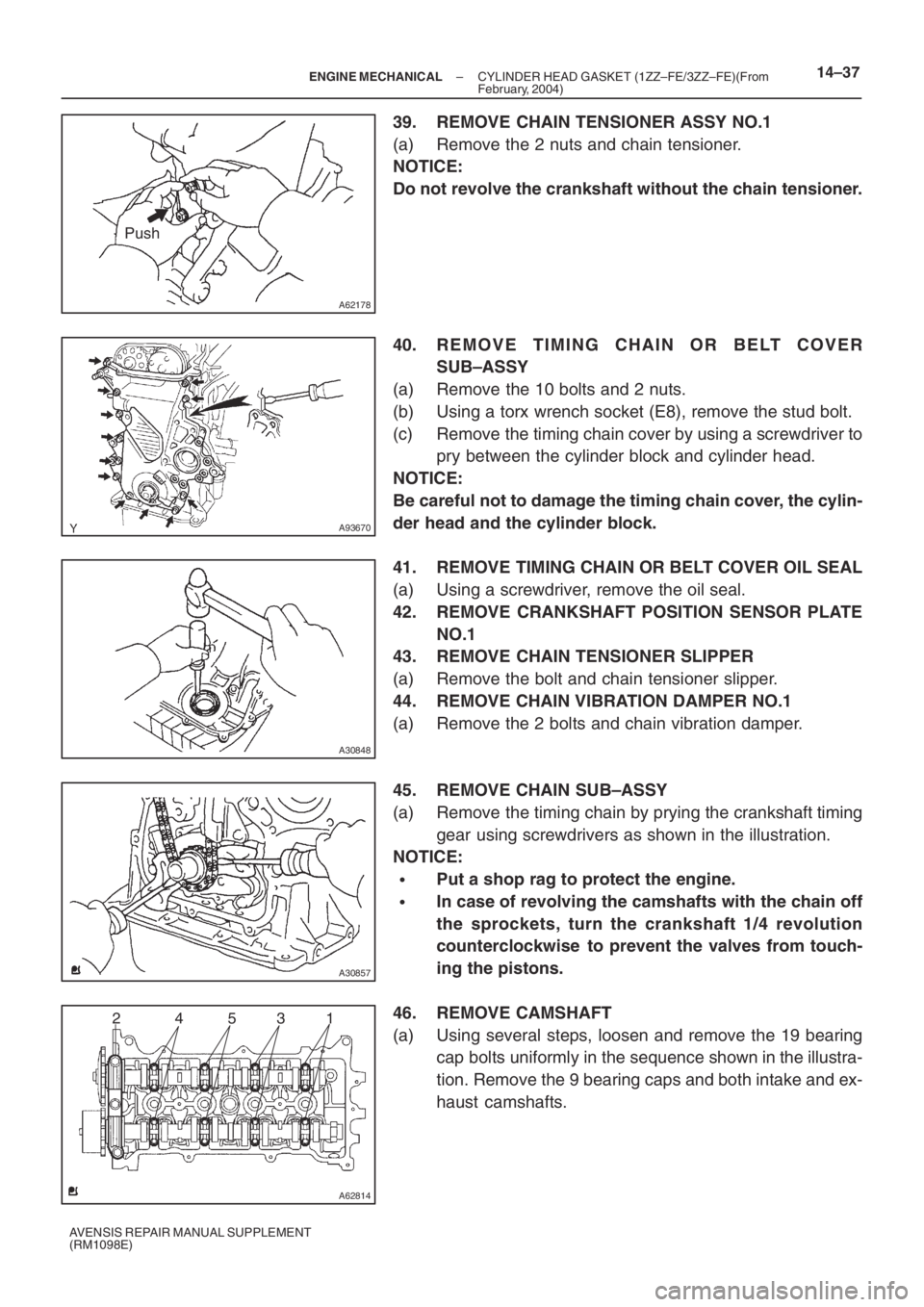
39. REMOVE CHAIN TENSIONER ASSY NO.1
(a) Remove the 2 nuts and chain tensioner.
NOTICE:
Do not revolve the crankshaft without the chain tensioner.
40. REMOVE TIMING CHAIN OR BELT COVER
SUB–ASSY
(a) Remove the 10 bolts and 2 nuts.
(b) Using a torx wrench socket (E8), remove the stud bolt.
(c) Remove the timing chain cover by using a screwdriver to
pry between the cylinder block and cylinder head.
NOTICE:
Be careful not to damage the timing chain cover, the cylin-
der head and the cylinder block.
41. REMOVE TIMING CHAIN OR BELT COVER OIL SEAL
(a) Using a screwdriver, remove the oil seal.
42. REMOVE CRANKSHAFT POSITION SENSOR PLATE
NO.1
43. REMOVE CHAIN TENSIONER SLIPPER
(a) Remove the bolt and chain tensioner slipper.
44. REMOVE CHAIN VIBRATION DAMPER NO.1
(a) Remove the 2 bolts and chain vibration damper.
45. REMOVE CHAIN SUB–ASSY
(a) Remove the timing chain by prying the crankshaft timing
gear using screwdrivers as shown in the illustration.
NOTICE:
�Put a shop rag to protect the engine.
�In case of revolving the camshafts with the chain off
the sprockets, turn the crankshaft 1/4 revolution
counterclockwise to prevent the valves from touch-
ing the pistons.
46. REMOVE CAMSHAFT
(a) Using several steps, loosen and remove the 19 bearing
cap bolts uniformly in the sequence shown in the illustra-
tion. Remove the 9 bearing caps and both intake and ex-
haust camshafts.
Page 5062 of 5135
A62837SST
A62180
Disconnect
Hook
Pin Turn
A62181
Plunger
Turn
Push
A62182
Seal Packing
– ENGINE MECHANICALCYLINDER HEAD GASKET (1ZZ–FE/3ZZ–FE)(From
February, 2004)14–43
AVENSIS REPAIR MANUAL SUPPLEMENT
(RM1098E)
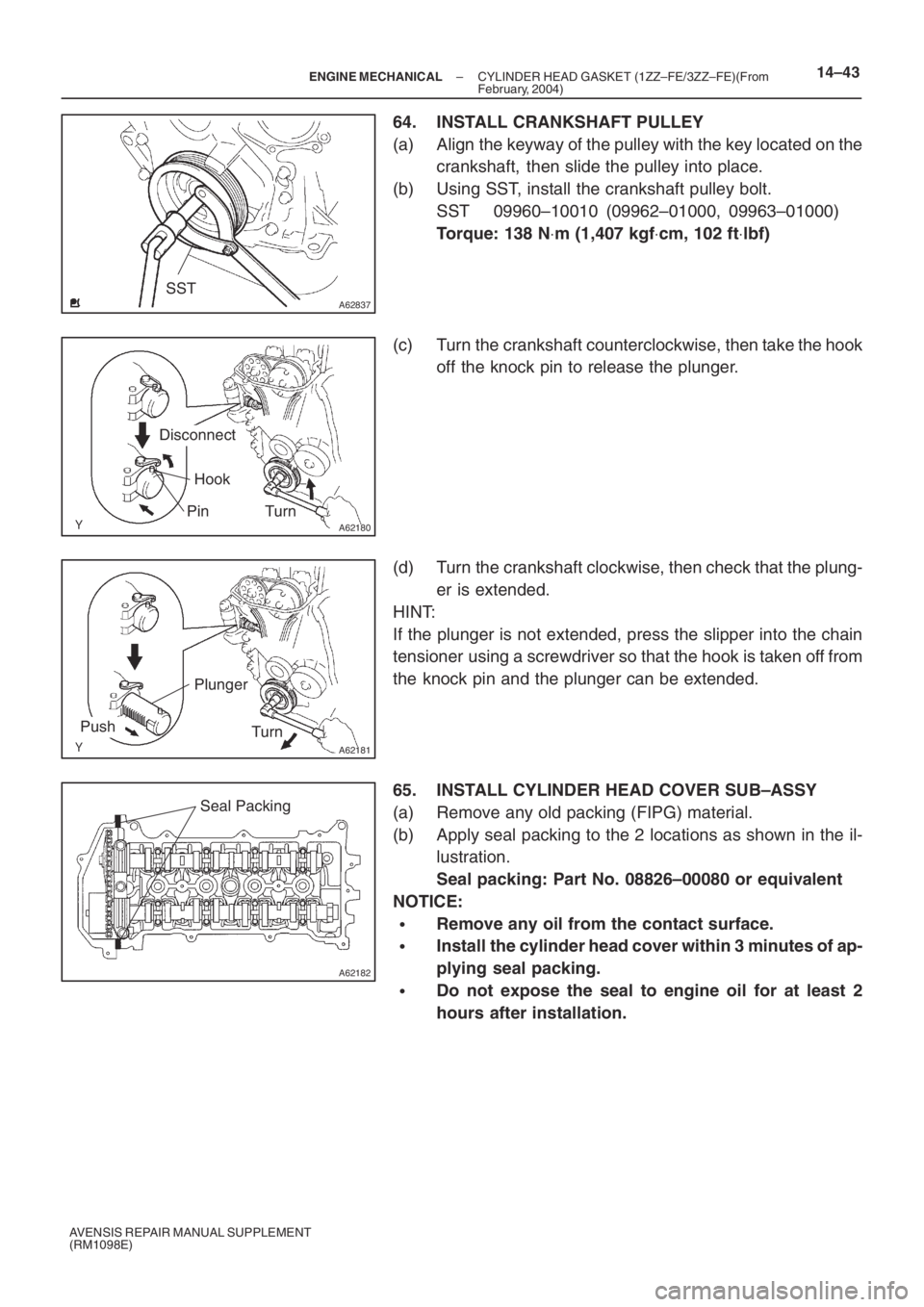
64. INSTALL CRANKSHAFT PULLEY
(a) Align the keyway of the pulley with the key located on the
crankshaft, then slide the pulley into place.
(b) Using SST, install the crankshaft pulley bolt.
SST 09960–10010 (09962–01000, 09963–01000)
Torque: 138 N⋅m (1,407 kgf⋅cm, 102 ft⋅lbf)
(c) Turn the crankshaft counterclockwise, then take the hook
off the knock pin to release the plunger.
(d) Turn the crankshaft clockwise, then check that the plung-
er is extended.
HINT:
If the plunger is not extended, press the slipper into the chain
tensioner using a screwdriver so that the hook is taken off from
the knock pin and the plunger can be extended.
65. INSTALL CYLINDER HEAD COVER SUB–ASSY
(a) Remove any old packing (FIPG) material.
(b) Apply seal packing to the 2 locations as shown in the il-
lustration.
Seal packing: Part No. 08826–00080 or equivalent
NOTICE:
�Remove any oil from the contact surface.
�Install the cylinder head cover within 3 minutes of ap-
plying seal packing.
�Do not expose the seal to engine oil for at least 2
hours after installation.
Page 5072 of 5135
A76719
A62838SST
A62838SST
A76713
– ENGINE MECHANICALPARTIAL ENGINE ASSY (1ZZ–FE/3ZZ–FE)(From
February, 2004)14–15
AVENSIS REPAIR MANUAL SUPPLEMENT
(RM1098E)
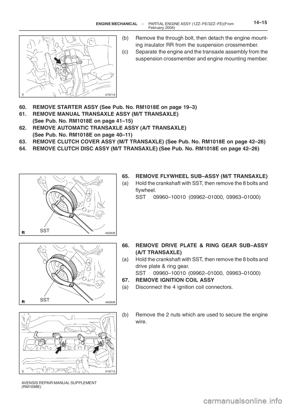
(b) Remove the through bolt, then detach the engine mount-
ing insulator RR from the suspension crossmember.
(c) Separate the engine and the transaxle assembly from the
suspension crossmember and engine mounting member.
60. REMOVE STARTER ASSY (See Pub. No. RM1018E on page 19–3)
61. REMOVE MANUAL TRANSAXLE ASSY (M/T TRANSAXLE)
(See Pub. No. RM1018E on page 41–15)
62. REMOVE AUTOMATIC TRANSAXLE ASSY (A/T TRANSAXLE)
(See Pub. No. RM1018E on page 40–11)
63. REMOVE CLUTCH COVER ASSY (M/T TRANSAXLE) (See Pub. No. RM1018E on page 42–26)
64. REMOVE CLUTCH DISC ASSY (M/T TRANSAXLE) (See Pub. No. RM1018E on page 42–26)
65. REMOVE FLYWHEEL SUB–ASSY (M/T TRANSAXLE)
(a) Hold the crankshaft with SST, then remove the 8 bolts and
flywheel.
SST 09960–10010 (09962–01000, 09963–01000)
66. REMOVE DRIVE PLATE & RING GEAR SUB–ASSY
(A/T TRANSAXLE)
(a) Hold the crankshaft with SST, then remove the 8 bolts and
drive plate & ring gear.
SST 09960–10010 (09962–01000, 09963–01000)
67. REMOVE IGNITION COIL ASSY
(a) Disconnect the 4 ignition coil connectors.
(b) Remove the 2 nuts which are used to secure the engine
wire.
Page 5080 of 5135
A62838SST
A62205
1
5
3
82
6
4
7
A62206
90�
A62838SST
A62204
1
5
3
82
6
4
7
– ENGINE MECHANICALPARTIAL ENGINE ASSY (1ZZ–FE/3ZZ–FE)(From
February, 2004)14–23
AVENSIS REPAIR MANUAL SUPPLEMENT
(RM1098E)
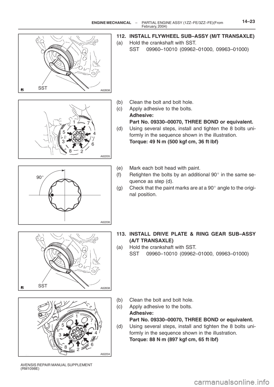
112. INSTALL FLYWHEEL SUB–ASSY (M/T TRANSAXLE)
(a) Hold the crankshaft with SST.
SST 09960–10010 (09962–01000, 09963–01000)
(b) Clean the bolt and bolt hole.
(c) Apply adhesive to the bolts.
Adhesive:
Part No. 09330–00070, THREE BOND or equivalent.
(d) Using several steps, install and tighten the 8 bolts uni-
formly in the sequence shown in the illustration.
Torque: 49 N⋅m (500 kgf⋅cm, 36 ft⋅lbf)
(e) Mark each bolt head with paint.
(f) Retighten the bolts by an additional 90� in the same se-
quence as step (d).
(g) Check that the paint marks are at a 90� angle to the origi-
nal position.
113. INSTALL DRIVE PLATE & RING GEAR SUB–ASSY
(A/T TRANSAXLE)
(a) Hold the crankshaft with SST.
SST 09960–10010 (09962–01000, 09963–01000)
(b) Clean the bolt and bolt hole.
(c) Apply adhesive to the bolts.
Adhesive:
Part No. 09330–00070, THREE BOND or equivalent.
(d) Using several steps, install and tighten the 8 bolts uni-
formly in the sequence shown in the illustration.
Torque: 88 N⋅m (897 kgf⋅cm, 65 ft⋅lbf)
Page 5115 of 5135
A01192
A63898
A01179
A64817
A64968
793
481062
15
– ENGINE MECHANICALCYLINDER BLOCK ASSY (1ZZ–FE/3ZZ–FE)
14–59
1ZZ–FE,3ZZ–FE ENGINE REPAIR MANUAL
(RM1099E)
7. REMOVE W/PIN PISTON SUB–ASSY
(a) Using a small screwdriver, pry out the 2 snap rings.
(b) Heat the piston up to 80 to 90�C (176 to 194�F).
(c) Using a plastic hammer and brass bar, lightly tap out the
piston pin, then remove the connecting rod.
HINT:
�The piston and pin are a matched set.
�Arrange the piston, pins, ring, connecting rod and bear-
ings in the correct order.
8. REMOVE CRANKSHAFT
(a) Remove the 10 bolts from the crankshaft bearing cap.
(b) Uniformly loosen the 10 bearing cap bolts in several
passes in the sequence shown in the illustration.
Page 5116 of 5135
A95732
Crankshaft
Bearing Cap
A64820
A32142
A64821
14–60
– ENGINE MECHANICALCYLINDER BLOCK ASSY (1ZZ–FE/3ZZ–FE)
1ZZ–FE,3ZZ–FE ENGINE REPAIR MANUAL
(RM1099E)
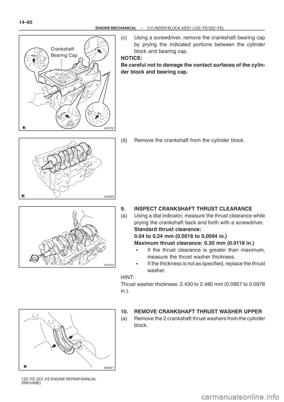
(c) Using a screwdriver, remove the crankshaft bearing cap
by prying the indicated portions between the cylinder
block and bearing cap.
NOTICE:
Be careful not to damage the contact surfaces of the cylin-
der block and bearing cap.
(d) Remove the crankshaft from the cylinder block.
9. INSPECT CRANKSHAFT THRUST CLEARANCE
(a) Using a dial indicator, measure the thrust clearance while
prying the crankshaft back and forth with a screwdriver.
Standard thrust clearance:
0.04 to 0.24 mm (0.0016 to 0.0094 in.)
Maximum thrust clearance: 0.30 mm (0.0118 in.)
�If the thrust clearance is greater than maximum,
measure the thrust washer thickness.
�If the thickness is not as specified, replace the thrust
washer.
HINT:
Thrust washer thickness: 2.430 to 2.480 mm (0.0957 to 0.0976
in.).
10. REMOVE CRANKSHAFT THRUST WASHER UPPER
(a) Remove the 2 crankshaft thrust washers from the cylinder
block.