Page 4862 of 5135

D26403
Thrust Bearing
Direct Clutch Assy
D26392
Thrust Bearing
Thrust Bearing Race
Overdrive Direct Clutch Hub
D03829
Overdrive
Direct Clutch
Drum Sub−assy
Dial Indicator
D26714Rear Planetary Sun Gear Assy
40−32
− AUTOMATIC TRANSMISSION / TRANSAUTOMATIC TRANSAXLE ASSY (U151E/U151F)
U151E, U151F A/T REPAIR MANUAL (RM1021U)
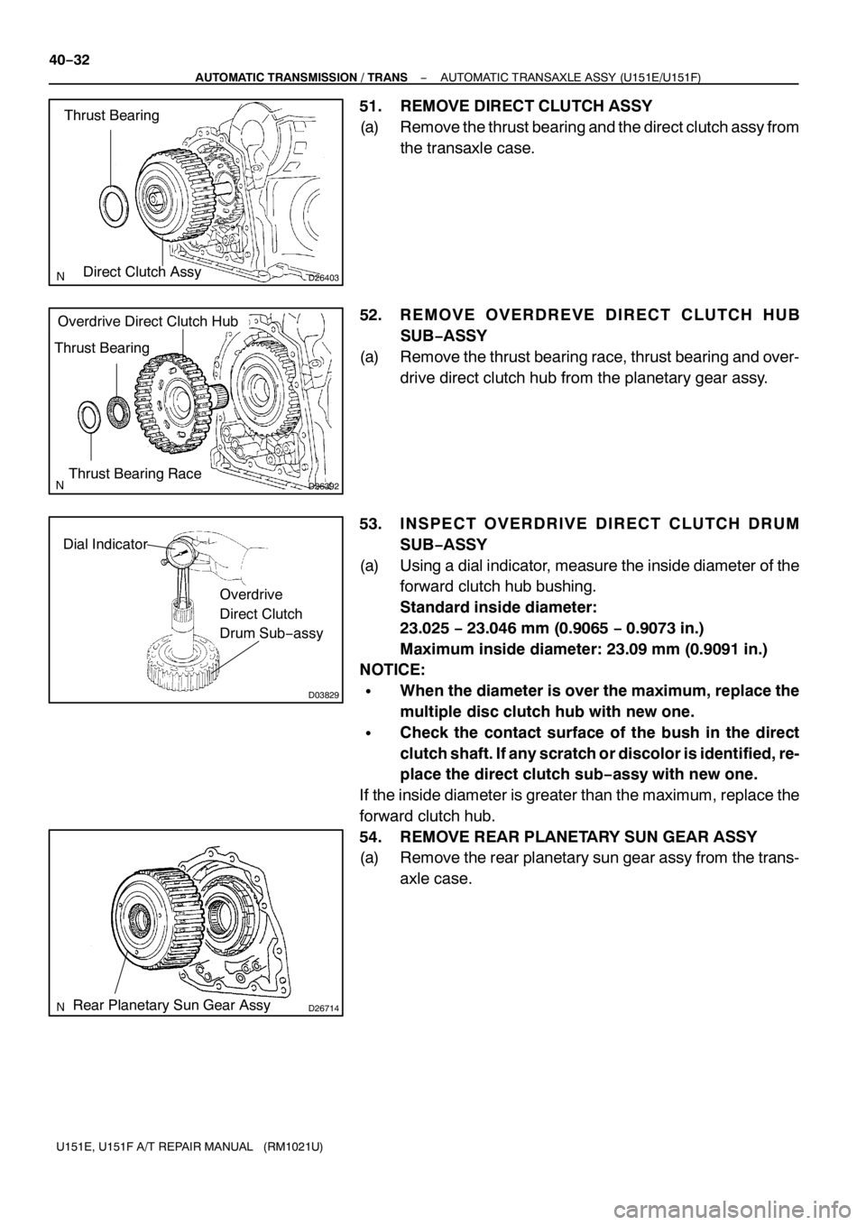
51. REMOVE DIRECT CLUTCH ASSY
(a) Remove the thrust bearing and the direct clutch assy from
the transaxle case.
52. REMOVE OVERDREVE DIRECT CLUTCH HUB
SUB−ASSY
(a) Remove the thrust bearing race, thrust bearing and over-
drive direct clutch hub from the planetary gear assy.
53. INSPECT OVERDRIVE DIRECT CLUTCH DRUM
SUB−ASSY
(a) Using a dial indicator, measure the inside diameter of the
forward clutch hub bushing.
Standard inside diameter:
23.025−23.046 mm (0.9065−0.9073 in.)
Maximum inside diameter: 23.09 mm (0.9091in.)
NOTICE:
SWhen the diameter is over the maximum, replace the
multiple disc clutch hub with new one.
SCheck the contact surface of the bush in the direct
clutch shaft. If any scratch or discolor is identified, re-
place the direct clutch sub−assy with new one.
If the inside diameter is greater than the maximum, replace the
forward clutch hub.
54. REMOVE REAR PLANETARY SUN GEAR ASSY
(a) Remove the rear planetary sun gear assy from the trans-
axle case.
Page 4870 of 5135
D03605
SSTHold
Turn
D03914
Underdrive
Clutch Drum
Oil Seal Ring
D26383
D03606
SST
Hold
Turn
D03915
Underdrive
Output
Shaft Oil
Seal Ring
40−40
− AUTOMATIC TRANSMISSION / TRANSAUTOMATIC TRANSAXLE ASSY (U151E/U151F)
U151E, U151F A/T REPAIR MANUAL (RM1021U)
76. REMOVE NEEDLE ROLLER BEARING
(a) Using SST, remove the needle−roller bearing from the
transaxle case.
SST 09387−00041 (09387−01010, 09387−01030,
09387−01040)
77. REMOVE UNDERDRIVE CLUTCH DRUM OIL SEAL
RING
(a) Remove the 2 oil seal rings from the transaxle case.
78. REMOVE TRANSAXLE CASE NO.1PLUG
(a) Remove the 2 transaxle case No. 1 plugs.
(b) Remove the 2 O−rings from the 2 transaxle case No. 1
plugs.
79. REMOVE UNDERDRIVE CYLINDRICAL ROLLER
BEARING
(a) Using SST, remove the underdrive cylindrical roller bear-
ing from the transaxle case.
SST 09514−35011
80. REMOVE UNDERDRIVE OUTPUT SHAFT OIL SEAL
RING
(a) Remove the oil seal ring from the transaxle housing.
Page 4874 of 5135

D26400
Transaxle Apply
Tube Clamp
Differential Gear Lube Apply Tube
D26383
Underdrive
Output Shaft
Oil Seal Ring
D03915
AT F
D03807
SST
D03914
Underdrive
Clutch Drum
Oil Seal Ring
AT F 40−44
− AUTOMATIC TRANSMISSION / TRANSAUTOMATIC TRANSAXLE ASSY (U151E/U151F)
U151E, U151F A/T REPAIR MANUAL (RM1021U)
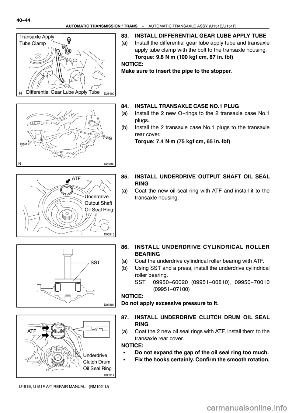
83. INSTALL DIFFERENTIAL GEAR LUBE APPLY TUBE
(a) Install the differential gear lube apply tube and transaxle
apply tube clamp with the bolt to the transaxle housing.
Torque: 9.8 N�m(100 kgf�cm, 87 in.�lbf)
NOTICE:
Make sure to insert the pipe to the stopper.
84. INSTALL TRANSAXLE CASE NO.1PLUG
(a) Install the 2 new O−rings to the 2 transaxle case No.1
plugs.
(b) Install the 2 transaxle case No.1 plugs to the transaxle
rear cover.
Torque: 7.4 N�m (75 kgf�cm, 65 in.�lbf)
85. INSTALL UNDERDRIVE OUTPUT SHAFT OIL SEAL
RING
(a) Coat the new oil seal ring with ATF and install it to the
transaxle housing.
86. INSTALL UNDERDRIVE CYLINDRICAL ROLLER
BEARING
(a) Coat the underdrive cylindrical roller bearing with ATF.
(b) Using SST and a press, install the underdrive cylindrical
roller bearing.
SST 09950−60020 (09951−00810), 09950−70010
(09951−07100)
NOTICE:
Do not apply excessive pressure to it.
87. INSTALL UNDERDRIVE CLUTCH DRUM OIL SEAL
RING
(a) Coat the 2 new oil seal rings with ATF, install them to the
transaxle rear cover.
NOTICE:
SDo not expand the gap of the oil seal ring too much.
SFix the hooks certainly. Confirm the smooth rotation.
Page 4890 of 5135

D03580
D09691
Parking Lock Pawl
Spring
Pawl Pin
D26386
D03579
Underdrive
Planetary
Gear Assy
40−60
− AUTOMATIC TRANSMISSION / TRANSAUTOMATIC TRANSAXLE ASSY (U151E/U151F)
U151E, U151F A/T REPAIR MANUAL (RM1021U)
121. INSTALL UNDERDRIVE CLUTCH ASSY
(a) Coat the bearing and bearing race with petroleum jelly,
install them onto the underdrive clutch.
Bearing and bearing race diameter: mm (in.)
InsideOutside
Bearing37.73 (1.4854)58.0 (2.2835)
Race29.9 (1.1772)55.5 (2.185)
(b) Install the underdrive clutch assy to the transaxle case.
NOTICE:
Installing the underdrive clutch drum sub−assy, be sure
not to damage the oil seal ring.
122. INSTALL PARKING LOCK PAWL
(a) Install the pawl pin and spring to the parking lock pawl.
(b) Temporarily install the parking lock pawl, shaft and spring
to the transaxle case, as shown in the illustration.
123. INSTALL UNDERDRIVE PLANETARY GEAR ASSY
(a) Install the underdrive planetary gear assy to the transaxle
case.
NOTICE:
Engage all the discs of underdrive clutch and hub splines
of the underdrive planetary gear assy firmly and assemble
them securely.
Page 4891 of 5135

D09693
D03576Pawl Shaft Clamp
D03875
E
D25511
Dimension (1)
Dimension (2)
D08087
Thrust Bearing Race No.1
− AUTOMATIC TRANSMISSION / TRANSAUTOMATIC TRANSAXLE ASSY (U151E/U151F)
40−61
U151E, U151F A/T REPAIR MANUAL (RM1021U)
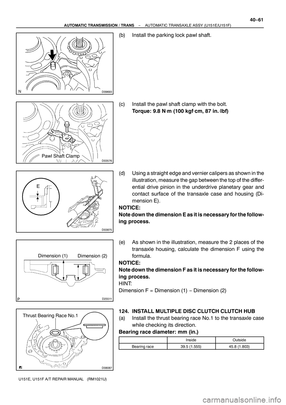
(b) Install the parking lock pawl shaft.
(c) Install the pawl shaft clamp with the bolt.
Torque: 9.8 N�m(100 kgf�cm, 87 in.�lbf)
(d) Using a straight edge and vernier calipers as shown in the
illustration, measure the gap between the top of the differ-
ential drive pinion in the underdrive planetary gear and
contact surface of the transaxle case and housing (Di-
mension E).
NOTICE:
Note down the dimension E as it is necessary for the follow-
ing process.
(e) As shown in the illustration, measure the 2 places of the
transaxle housing, calculate the dimension F using the
formula.
NOTICE:
Note down the dimension F as it is necessary for the follow-
ing process.
HINT:
Dimension F = Dimension (1)−Dimension (2)
124. INSTALL MULTIPLE DISC CLUTCH CLUTCH HUB
(a) Install the thrust bearing race No.1 to the transaxle case
while checking its direction.
Bearing race diameter: mm (in.)
InsideOutside
Bearing race39.5 (1.555)45.8 (1.803)
Page 4895 of 5135

D25608
C
C
CAB2WD:
4WD:
B
D
C CC
CB
B
A
A
D08091
D03631
D26468
SST
− AUTOMATIC TRANSMISSION / TRANSAUTOMATIC TRANSAXLE ASSY (U151E/U151F)
40−65
U151E, U151F A/T REPAIR MANUAL (RM1021U)
(c) Install the transaxle housing and 16 bolts to the transaxle
case.
Torque:
Bolt A: 25 N�m (255 kgf�cm,18ft�lbf)
Bolt B: 33 N�m (337 kgf�cm, 24 ft�lbf)
Bolt C: 29 N�m (295 kgf�cm, 21ft�lbf)
Bolt D: 22 N�m (226 kgf�cm,16.0 ft�lbf)
HINT:
Apply seal packing or equivalent to the bolt A and D.
Seal packing:
THREE BOND 2403 or equivalent
Bolt length:
Bolt A: 50 mm (1.969 in.)
Bolt B: 50 mm (1.969 in.)
Bolt C: 42 mm (1.654 in.)
Bolt D: 72 mm (2.835 in.)
NOTICE:
Because the bolt A is a seal bolt, apply the seal packing to
new bolts and tighten them within10 minutes after applica-
tion.
132. INSPECT INPUT SHAFT ENDPLAY
(a) Using a dial indicator, measure the input shaft end play.
End play: 0.262−1.249 mm (0.0100−0.0494 in.)
133. FIX AUTOMATIC TRANSAXLE ASSY
(a) Fix the transaxle assy.
134. INSTALL MANUAL VALVE LEVER SHAFT OIL SEAL
(a) Coat a new oil seal with MP grease.
(b) Install the oil seal to the transaxle case.
SST 09950−60010 (09951−00230), 09950−70010
(09951−07100)
Oil seal drive in depth: 0�á0.5 mm (0�á0.0197 in.)
Page 4896 of 5135
D26382
Parking Lock Rod Sub−assy
D03565
Spacer
D03564
D26765
D03559
40−66
− AUTOMATIC TRANSMISSION / TRANSAUTOMATIC TRANSAXLE ASSY (U151E/U151F)
U151E, U151F A/T REPAIR MANUAL (RM1021U)
135. INSTALL PARKING LOCK ROD SUB−ASSY
(a) Install the parking lock rod to the manual valve lever.
136. INSTALL MANUAL VALVE LEVER SUB−ASSY
(a) Install a new spacer and manual valve lever shaft to the
transaxle case.
NOTICE:
Do not damage on the oil seal during assembling the shaft
to the transaxle case.
(b) Using a pin punch and hammer, drive in a new pin.
(c) Turn the spacer and the lever shaft to align the small hole
for locating the staking position in the spacer with the
staking position mark on the lever shaft.
(d) Using a pin punch, stake the spacer through the small
hole.
(e) Check that the spacer does not turn.
137. INSTALL MANUAL VALVE LEVER SHAFT RETAINER
SPRING
(a) Using needle−nose pliers, install the retainer spring.
NOTICE:
Hang the spring on the shaft certainly.
Page 4903 of 5135
D09641
D09642
D09643
D09644
− AUTOMATIC TRANSMISSION / TRANSAUTOMATIC TRANSAXLE ASSY (U151E/U151F)
40−73
U151E, U151F A/T REPAIR MANUAL (RM1021U)
(d) Turn the lever counterclockwise until it stops, and then
turn it clockwise 2 notches.
(e) Remove the control shaft lever.
(f) Align the groove with neutral basic line.
(g) Tighten the 2 bolts.
Torque: 5.4 N�m (55 kgf�cm, 48 in.�lbf)
(h) Using a screwdriver, stake the nut with the nut stopper.
(i) Install the control shaft lever, washer and nut.
Torque:13N�m(130 kgf�cm, 9 ft�lbf)
158. INSTALL SPEEDOMETER DRIVEN HOLE (ATM) COVER SUB−ASSY
(a) Coat a new O−ring with ATF and install it to the speedometer driven hole cover.
(b) Install the bolt and speedometer driven hole cover sub−assy to the transaxle assy.
Torque: 6.9 N�m (70 kgf�cm, 61ft�lbf)