Page 4643 of 5135
A09612
1st
2nd 5th
3rd
4th 6th 7th
A09609
Timing Mark
Timing
Mark
Timing Mark
A09589
Hexagon
Wrench
(1.27 mm)
(A)
A09623
14−142
− ENGINE MECHANICALTIMING BELT (1CD−FTV)(From September, 2003)
AVENSIS Supplement (RM1045E)
24. INSTALL TIMING BELT
NOTICE:
The engine should be cold.
(a) Remove any oil or water on each pulley, then keep them
clean.
NOTICE:
Do not use any cleaning agent.
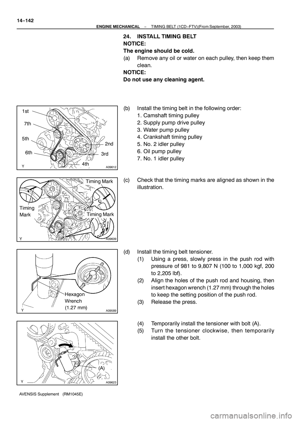
(b) Install the timing belt in the following order:
1. Camshaft timing pulley
2. Supply pump drive pulley
3. Water pump pulley
4. Crankshaft timing pulley
5. No. 2 idler pulley
6. Oil pump pulley
7. No. 1 idler pulley
(c) Check that the timing marks are aligned as shown in the
illustration.
(d) Install the timing belt tensioner.
(1) Using a press, slowly press in the push rod with
pressure of 981 to 9,807 N (100 to 1,000 kgf, 200
to 2,205 lbf).
(2) Align the holes of the push rod and housing, then
insert hexagon wrench (1.27 mm) through the holes
to keep the setting position of the push rod.
(3) Release the press.
(4) Temporarily install the tensioner with bolt (A).
(5) Turn the tensioner clockwise, then temporarily
install the other bolt.
Page 4646 of 5135
A09602
Seal
Packing
Gasket
Groove
A61186
SST
−
ENGINE MECHANICAL TIMING BELT (1CD−FTV)(From September, 2003)
14 −145
AVENSIS Supplement (RM1045E)
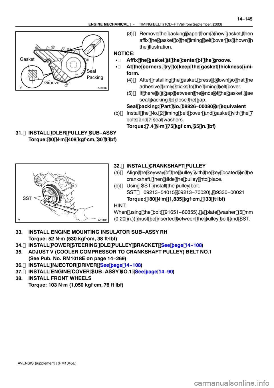
(3) Remove the backing paper from a new gasket, then
affix the gasket to the timing belt cover as shown in
the illustration.
NOTICE:
S Affix the gasket at the center of the groove.
S At the corners, try to keep the gasket thickness uni-
form.
(4) After installing the gasket, press it down so that the
adhesive firmly sticks to the timing belt cover.
(5) If there is a gap between the ends of the gasket, use
seal packing to close the gap.
Seal packing: Part No. 08826 −00080 or equivalent
(b) Install the No. 2 timing belt cover and gasket with the 7
bolts and 7 seal washers.
Torque: 7.4 N �m (75 kgf �cm, 65 in. �lbf)
31. INSTALL IDLER PULLEY SUB −ASSY
Torque: 40 N �m (408 kgf �cm, 30 ft �lbf)
32. INSTALL CRANKSHAFT PULLEY
(a) Align the keyway of the pulley with the key located on the crankshaft, then slide the pulley into place.
(b) Using SST, install the pulley bolt.
SST 09213 −54015 (09213 −70020), 09330 −00021
Torque: 180 N·m (1,835 kgf·cm, 133 ft·lbf)
HINT:
When using the bolt (91651 −60855), a plate washer (5 mm
(0.20 in.)) must be inserted between the pulley bolt and SST.
33. INSTALL ENGINE MOUNTING INSULATOR SUB −ASSY RH
Torque: 52 N·m (530 kgf·cm, 38 ft·lbf)
34. INSTALL POWER STEERING IDLE PULLEY BRACKET (See page 14 −108)
35. ADJUST V (COOLER COMPRESSOR TO CRANKSHAFT PULLEY) BELT NO.1 (See Pub. No. RM1018E on page 14 −269)
36. INSTALL INJECTOR DRIVER (See page 14 −108)
37. INSTALL ENGINE COVER SUB −ASSY NO.1 (See page 14 −90)
38. INSTALL FRONT WHEELS Torque: 103 N �m (1,050 kgf �cm, 76 ft �lbf)
Page 4647 of 5135
141NH−01
A85614
Clip
ClipRetainer
8.0 (82, 71 in.�lbf)
Engine Cover Sub−assy No. 1
Clip
Engine Under Cover RH
Clip
w/ A/C:
V (Cooler
Compressor to
Crankshaft
Pulley) Belt No. 1
Engine Mounting Insulator Sub−assy RH
x3
5.5 (56, 49 in.·lbf)
Injector Driver
39 (398, 29)
72 (734, 53)
52 (530, 38)
Power Steering
Idle Pulley
Bracket
52 (530, 38)
52 (530, 38)
Radiator Support Opening Cover
: Specified torqueN·m (kgf·cm, ft·lbf)Engine Wire Vacuum Hose
Engine Under Cover Sub−assy No. 1 14−136
− ENGINE MECHANICALTIMING BELT (1CD−FTV)(From September, 2003)
AVENSIS Supplement (RM1045E)
TIMING BELT (1CD−FTV)(From September, 2003)
COMPONENTS
Page 4655 of 5135
A61186
SST
A84289
14−11 4−
ENGINE MECHANICAL PARTIAL ENGINE ASSY (1CD −FTV)(From September,
2003)
AVENSIS Supplement (RM1045E)
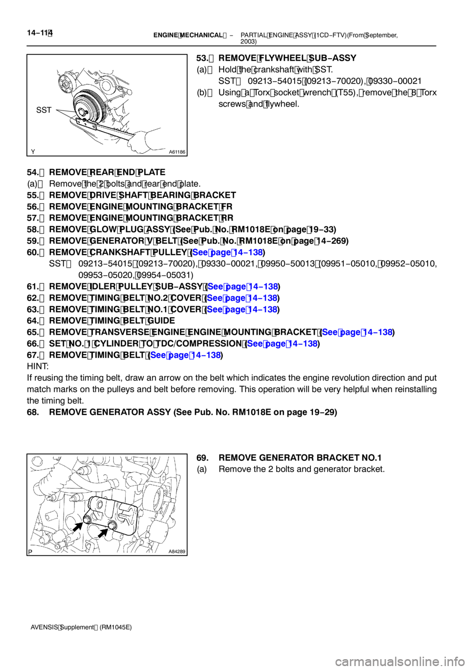
53. REMOVE FLYWHEEL SUB −ASSY
(a) Hold the crankshaft with SST. SST 09213 −54015 (09213 −70020), 09330 −00021
(b) Using a Torx socket wrench (T55), remove the 8 Torx
screws and flywheel.
54. REMOVE REAR END PLATE
(a) Remove the 2 bolts and rear end plate.
55. REMOVE DRIVE SHAFT BEARING BRACKET
56. REMOVE ENGINE MOUNTING BRACKET FR
57. REMOVE ENGINE MOUNTING BRACKET RR
58. REMOVE GLOW PLUG ASSY (See Pub. No. RM1018E on page 19 −33)
59. REMOVE GENERATOR V BELT (See Pub. No. RM1018E on page 14 −269)
60. REMOVE CRANKSHAFT PULLEY (See page 14 −138)
SST 09213 −54015 (09213 −70020), 09330 −00021, 09950 −50013 (09951 −05010, 09952 −05010,
09953 −05020, 09954 −05031)
61. REMOVE IDLER PULLEY SUB −ASSY (See page 14 −138)
62. REMOVE TIMING BELT NO.2 COVER (See page 14 −138)
63. REMOVE TIMING BELT NO.1 COVER (See page 14 −138)
64. REMOVE TIMING BELT GUIDE
65. REMOVE TRANSVERSE ENGINE ENGINE MOUNTING BRACKET (See page 14 −138)
66. SET NO. 1 CYLINDER TO TDC/COMPRESSION (See page 14 −138)
67. REMOVE TIMING BELT (See page 14 −138)
HINT:
If reusing the timing belt, draw an arrow on the belt which indicates the engine revolution direction and put
match marks on the pulleys and belt before removing. This operation will be very helpful when reinstalling
the timing belt.
68. REMOVE GENERATOR ASSY (See Pub. No. RM1018E on page 19 −29)
69. REMOVE GENERATOR BRACKET NO.1
(a) Remove the 2 bolts and generator bracket.
Page 4670 of 5135
A61186
SST
A57108
Adhesive
−
ENGINE MECHANICAL PARTIAL ENGINE ASSY (1CD −FTV)(From September,
2003)14 −129
AVENSIS Supplement (RM1045E)
166. INSTALL V −RIBBED BELT TENSIONER ASSY
Torque: 31 N �m (316 kgf �cm, 23 ft �lbf)
167. INSTALL GENERATOR BRACKET NO.1 Torque: 37 N �m (377 kgf �cm, 27 ft �lbf)
168. INSTALL GENERATOR ASSY (See Pub. No. RM1018E on page 19 −29)
169. SET NO. 1 CYLINDER TO TDC/COMPRESSION (See page 14 −138)
SST 09960 −10010 (09962 −01000, 09963 −01000)
170. INSTALL TIMING BELT (See page 14 −138)
171. CHECK VALVE TIMING (See page 14 −138)
172. INSTALL TRANSVERSE ENGINE ENGINE MOUNTING BRACKET (See page 14 −138)
173. INSTALL TIMING BELT GUIDE (See page 14 −138)
174. INSTALL TIMING BELT NO.1 COVER (See page 14 −138)
175. INSTALL TIMING BELT NO.2 COVER (See page 14 −138)
176. INSTALL IDLER PULLEY SUB −ASSY
Torque: 40 N �m (408 kgf �cm, 30 ft �lbf)
177. INSTALL CRANKSHAFT PULLEY (See page 14 −138)
SST 09213 −54015 (09213 −70020), 09330 −00021
178. INSTALL GLOW PLUG ASSY (See Pub. No. RM1018E on page 19 −33)
179. INSTALL ENGINE MOUNTING BRACKET RR
Torque: 64 N �m (653 kgf �cm, 47 ft �lbf)
180. INSTALL ENGINE MOUNTING BRACKET FR Torque: 64 N �m (653 kgf �cm, 47 ft �lbf)
181. INSTALL DRIVE SHAFT BEARING BRACKET Torque: 64 N �m (653 kgf �cm, 47 ft �lbf)
182. INSTALL REAR END PLATE Torque: 8.4 N �m (86 kgf �cm, 74 in. �lbf)
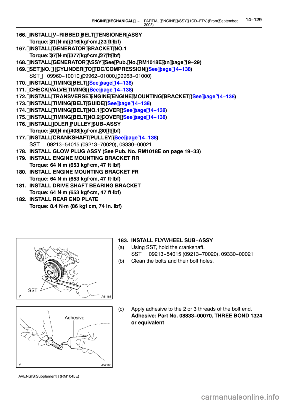
183. INSTALL FLYWHEEL SUB −ASSY
(a) Using SST, hold the crankshaft. SST 09213 −54015 (09213 −70020), 09330 −00021
(b) Clean the bolts and their bolt holes.
(c) Apply adhesive to the 2 or 3 threads of the bolt end. Adhesive: Part No. 08833 −00070, THREE BOND 1324
or equivalent
Page 4679 of 5135
SST (A)
SST (B)
A09616
A09615
Magnetic
Finger
A54826
EXAMPLE (Intake):
Measured valve clearance = 0.45 mm (0.0177 in.)
0.45 mm (0.0177 in.)−0.25 mm (0.0098 in.) = 0.20 mm (0.0078 in.)
(Measured−Specification = Excess clearance)
Used shim measurement = 2.80 mm (0.1102 in.)
0.20 mm (0.0078 in.) + 2.80 mm (0.1102 in.) = 3.00 mm (0.1181 in.)
(Excess clearance + Used shim = Ideal new shim)
Closest new shim = 3.00 mm (0.1181 in.)
Select No. 21 shim
14−92− ENGINE MECHANICALVALVE CLEARANCE (1CD−FTV)(From September,
2003)
AVENSIS Supplement (RM1045E)
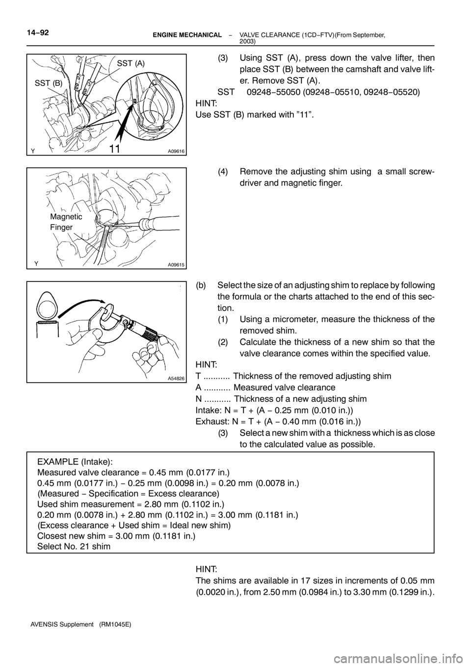
(3) Using SST (A), press down the valve lifter, then
place SST (B) between the camshaft and valve lift-
er. Remove SST (A).
SST 09248−55050 (09248−05510, 09248−05520)
HINT:
Use SST (B) marked with ”11”.
(4) Remove the adjusting shim using a small screw-
driver and magnetic finger.
(b) Select the size of an adjusting shim to replace by following
the formula or the charts attached to the end of this sec-
tion.
(1) Using a micrometer, measure the thickness of the
removed shim.
(2) Calculate the thickness of a new shim so that the
valve clearance comes within the specified value.
HINT:
T ........... Thickness of the removed adjusting shim
A ........... Measured valve clearance
N ........... Thickness of a new adjusting shim
Intake: N = T + (A−0.25 mm (0.010 in.))
Exhaust: N = T + (A−0.40 mm (0.016 in.))
(3) Select a new shim with a thickness which is as close
to the calculated value as possible.
HINT:
The shims are available in 17 sizes in increments of 0.05 mm
(0.0020 in.), from 2.50 mm (0.0984 in.) to 3.30 mm (0.1299 in.).
Page 4685 of 5135
141ND−01
A57063
Measure Point for Belt
Deflection and Tension
Alternator
Crankshaft Compressor
P/SP/S
Alternator Crankshaft
A/C Equipped
A/C Not Equipped
−
ENGINE MECHANICAL ENGINE (1CD−FTV)(From September, 2003)
14 −87
AVENSIS Supplement (RM1045E)
ENGINE (1CD −FTV)(From September, 2003)
INSPECTION
1. INSPECT ENGINE COOLANT (See page 16 −15)
2. INSPECT ENGINE OIL (See page 17 −9)
3. INSPECT BATTERY (See Pub. No. RM1018E on page 19 −26)
4. INSPECT AIR CLEANER FILTER ELEMENT SUB −ASSY
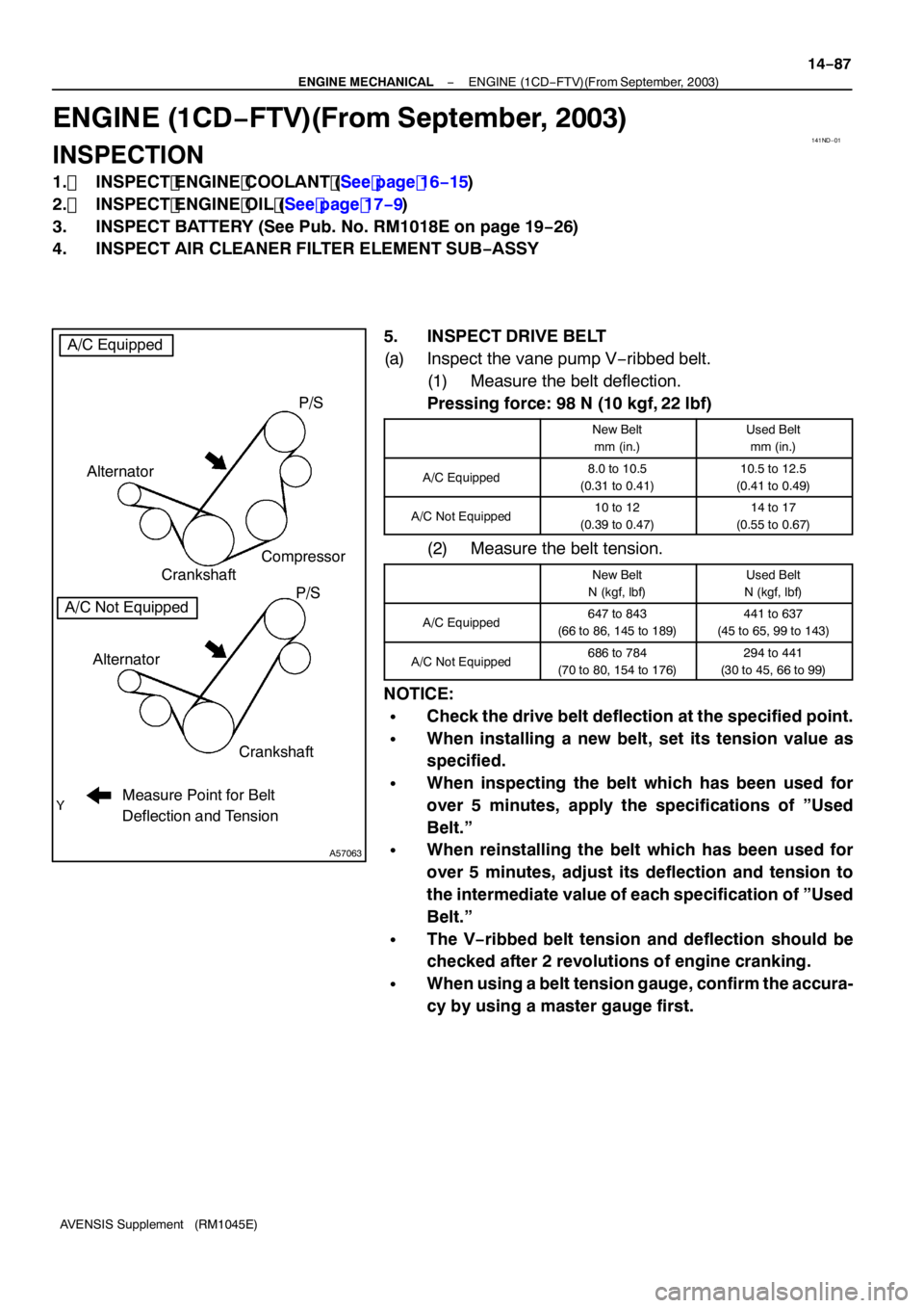
5. INSPECT DRIVE BELT
(a) Inspect the vane pump V −ribbed belt.
(1) Measure the belt deflection.
Pressing force: 98 N (10 kgf, 22 lbf)
New Belt
mm (in.)Used Belt mm (in.)
A/C Equipped8.0 to 10.5
(0.31 to 0.41)10.5 to 12.5
(0.41 to 0.49)
A/C Not Equipped10 to 12
(0.39 to 0.47)14 to 17
(0.55 to 0.67)
(2) Measure the belt tension.
New Belt
N (kgf, lbf)Used Belt
N (kgf, lbf)
A/C Equipped647 to 843
(66 to 86, 145 to 189)441 to 637
(45 to 65, 99 to 143)
A/C Not Equipped686 to 784
(70 to 80, 154 to 176)294 to 441
(30 to 45, 66 to 99)
NOTICE:
SCheck the drive belt deflection at the specified point.
SWhen installing a new belt, set its tension value as
specified.
SWhen inspecting the belt which has been used for
over 5 minutes, apply the specifications of ”Used
Belt.”
SWhen reinstalling the belt which has been used for
over 5 minutes, adjust its deflection and tension to
the intermediate value of each specification of ”Used
Belt.”
SThe V −ribbed belt tension and deflection should be
checked after 2 revolutions of engine cranking.
SWhen using a belt tension gauge, confirm the accura-
cy by using a master gauge first.
Page 4688 of 5135
141BS−02
A77421
Cut Position
A77422SST
14
−86
−
ENGINE MECHANICAL ENGINE REAR OIL SEAL (2AZ −FSE)
AVENSIS Supplement (RM1045E)
ENGINE REAR OIL SEAL (2AZ −FSE)
REPLACEMENT
1. REMOVE AUTOMATIC TRANSAXLE ASSY (See page 40 −3)
2. REMOVE DRIVE PLATE & RING GEAR SUB −ASSY (See page 14 −23)
SST 09213 −54015 (91651 −60855), 09330 −00021
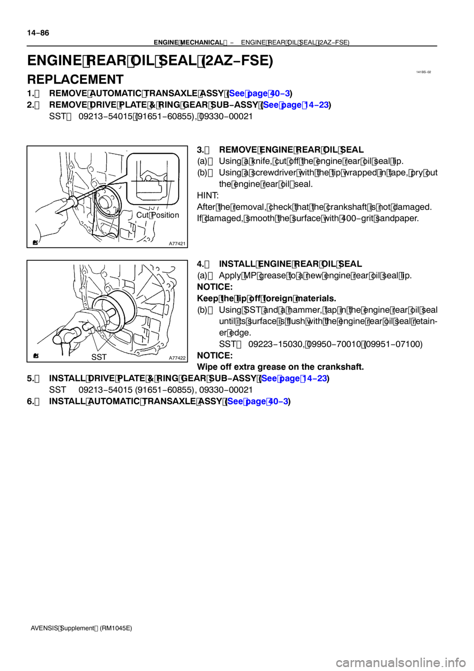
3. REMOVE ENGINE REAR OIL SEAL
(a) Using a knife, cut off the engine rear oil seal lip.
(b) Using a screwdriver with the tip wrapped in tape, pry out the engine rear oil seal.
HINT:
After the removal, check that the crankshaft is not damaged.
If damaged, smooth the surface with 400 −grit sandpaper.
4. INSTALL ENGINE REAR OIL SEAL
(a) Apply MP grease to a new engine rear oil seal lip.
NOTICE:
Keep the lip off foreign materials.
(b) Using SST and a hammer, tap in the engine rear oil seal until its surface is flush with the engine rear oil seal retain-
er edge.
SST 09223 −15030, 09950 −70010 (09951 −07100)
NOTICE:
Wipe off extra grease on the crankshaft.
5. INSTALL DRIVE PLATE & RING GEAR SUB −ASSY (See page 14 −23)
SST 09213 −54015 (91651 −60855), 09330 −00021
6. INSTALL AUTOMATIC TRANSAXLE ASSY (See page 40 −3)