Page 3847 of 5135
A57097
A57098
A09650
1 3
24
576
8
9
10 11
12
13 14
15
A09624
± ENGINE MECHANICALPARTIAL ENGINE ASSY (1CD±FTV)
14±5
1CD±FTV ENGINE REPAIR MANUAL (RM927E)
11. REMOVE CAMSHAFT OIL SEAL RETAINER
(a) Remove the 4 bolts.
(b) Using a screwdriver, remove the oil seal retainer by prying
the portions between the oil seal retainer and camshaft
bearing cap.
12. REMOVE WATER PUMP ASSY
(a) Remove the 7 bolts, water pump and gasket.
13. REMOVE CAMSHAFT SUB±ASSY, NO.2
(a) Uniformly loosen and remove the 15 bearing cap bolts in
several passes in the sequence shown.
(b) Remove the 5 bearing caps.
(c) Remove the camshaft No. 2.
14. REMOVE CAMSHAFT SUB±ASSY, NO.1
(a) Remove the camshaft from the cylinder head.
(b) Remove the camshaft carrier from the cylinder head.
Page 3850 of 5135
A09619
SST
A09620
B07976
A56700
SST
14±8
± ENGINE MECHANICALPARTIAL ENGINE ASSY (1CD±FTV)
1CD±FTV ENGINE REPAIR MANUAL (RM927E)
22. REMOVE CYLINDER BLOCK WATER DRAIN COCK SUB±ASSY
23. REMOVE CAMSHAFT OIL SEAL
(a) Using a screwdriver and a hammer, tap out the oil seal.
24. INSTALL CAMSHAFT OIL SEAL
(a) Using SST and a hammer, tap in a new oil seal until its sur-
face is flush with the camshaft oil seal retainer edge.
SST 09223±46011
25. REMOVE CRANKSHAFT SEAL
(a) Using a screwdriver and a hammer, tap out the oil seal.
26. INSTALL CRANKSHAFT SEAL
(a) Using SST and a hammer, tap in a new oil seal until its sur-
face is flush with the oil pump edge.
SST 09316±60011 (09316±00011, 09316±00021)
Page 3858 of 5135

A62959
SST (B)SST (A)
A09615
Magnetic
Finger
A54826
SST (A)
SST (B)
A09686
14±16
± ENGINE MECHANICALPARTIAL ENGINE ASSY (1CD±FTV)
1CD±FTV ENGINE REPAIR MANUAL (RM927E)
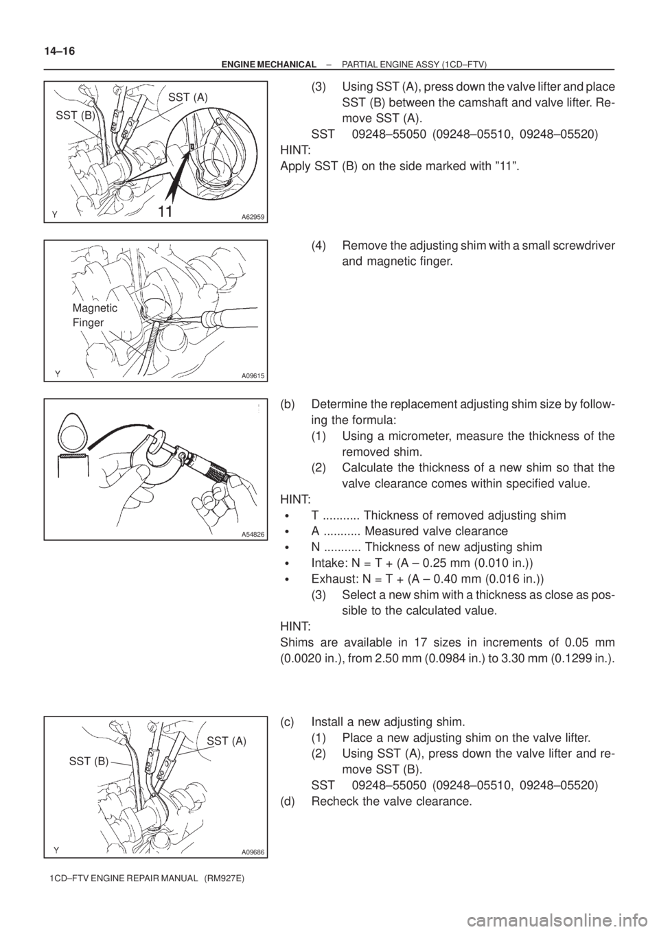
(3) Using SST (A), press down the valve lifter and place
SST (B) between the camshaft and valve lifter. Re-
move SST (A).
SST 09248±55050 (09248±05510, 09248±05520)
HINT:
Apply SST (B) on the side marked with º11º.
(4) Remove the adjusting shim with a small screwdriver
and magnetic finger.
(b) Determine the replacement adjusting shim size by follow-
ing the formula:
(1) Using a micrometer, measure the thickness of the
removed shim.
(2) Calculate the thickness of a new shim so that the
valve clearance comes within specified value.
HINT:
�T ........... Thickness of removed adjusting shim
�A ........... Measured valve clearance
�N ........... Thickness of new adjusting shim
�Intake: N = T + (A ± 0.25 mm (0.010 in.))
�Exhaust: N = T + (A ± 0.40 mm (0.016 in.))
(3) Select a new shim with a thickness as close as pos-
sible to the calculated value.
HINT:
Shims are available in 17 sizes in increments of 0.05 mm
(0.0020 in.), from 2.50 mm (0.0984 in.) to 3.30 mm (0.1299 in.).
(c) Install a new adjusting shim.
(1) Place a new adjusting shim on the valve lifter.
(2) Using SST (A), press down the valve lifter and re-
move SST (B).
SST 09248±55050 (09248±05510, 09248±05520)
(d) Recheck the valve clearance.
Page 3880 of 5135

±
DIAGNOSTICS SFI SYSTEM(1AZ±FE)
05±177
AVENSIS REPAIR MANUAL (RM1018E)
9REPLACE CAMSHAFT TIMING GEAR ASSY
GO
10CHECK FOR BLOCKAGE(OCV, OIL CHECK VALVE AND OIL HOLE)
NGREPAIR OR REPLACE
OK
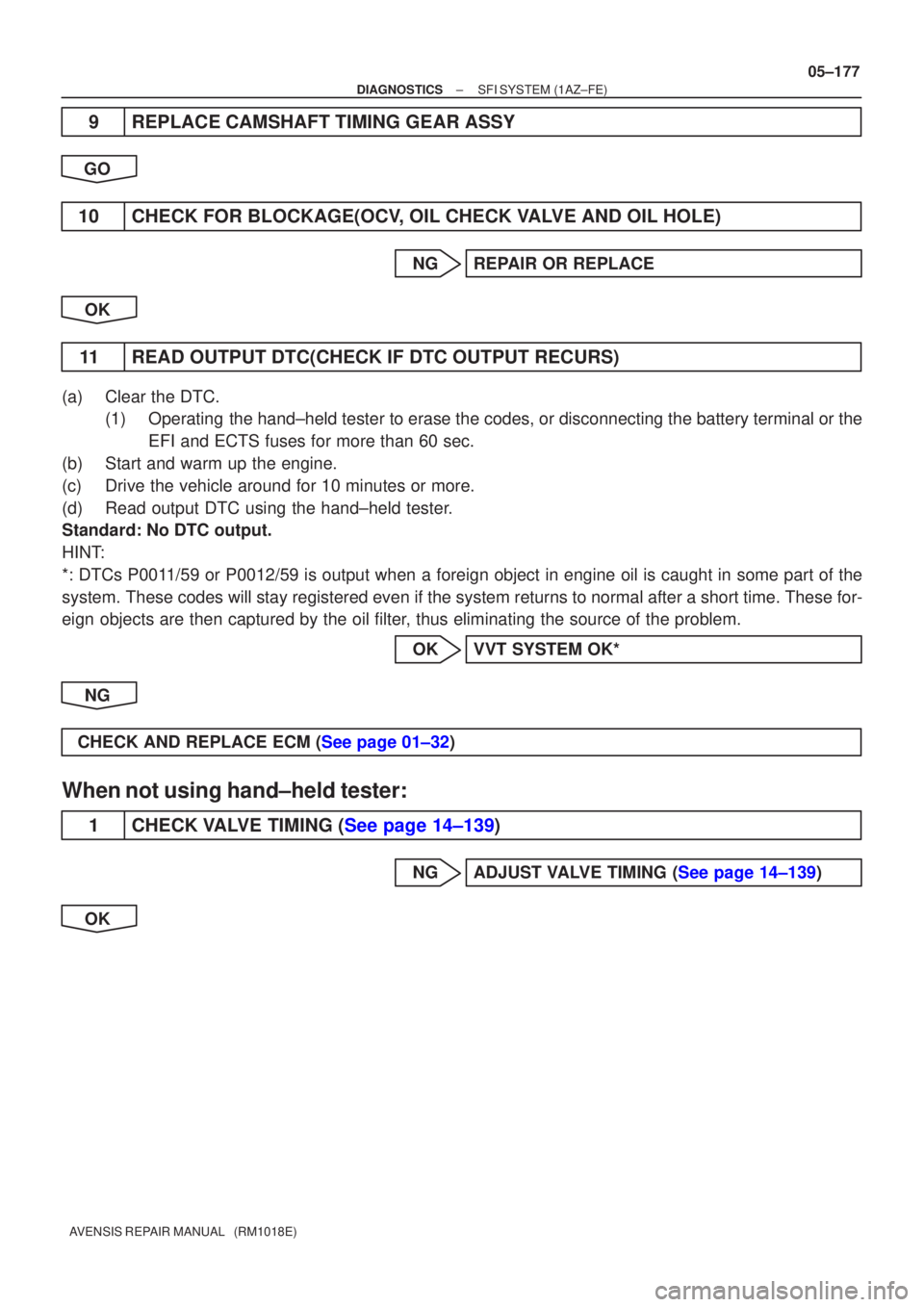
11READ OUTPUT DTC(CHECK IF DTC OUTPUT RECURS)
(a)Clear the DTC. (1)Operating the hand±held tester to erase the codes, or disconnecting the batter\
y terminal or the
EFI and ECTS fuses for more than 60 sec.
(b)Start and warm up the engine.
(c)Drive the vehicle around for 10 minutes or more.
(d)Read output DTC using the hand±held tester.
Standard: No DTC output.
HINT:
*: DTCs P0011/59 or P0012/59 is output when a foreign object in engine oil is caught\
in some part of the
system. These codes will stay registered even if the system returns to normal a\
fter a short time. These for-
eign objects are then captured by the oil filter, thus eliminating the source of the problem.
OKVVT SYSTEM OK*
NG
CHECK AND REPLACE ECM (See page 01±32)
When not using hand±held tester:
1CHECK VALVE TIMING (See page 14±139)
NGADJUST VALVE TIMING (See page 14±139)
OK
Page 3881 of 5135

A76968
C2
(±) (+)
Camshaft Timing Oil Control Valve
05±178
± DIAGNOSTICSSFI SYSTEM (1AZ±FE)
AVENSIS REPAIR MANUAL (RM1018E)
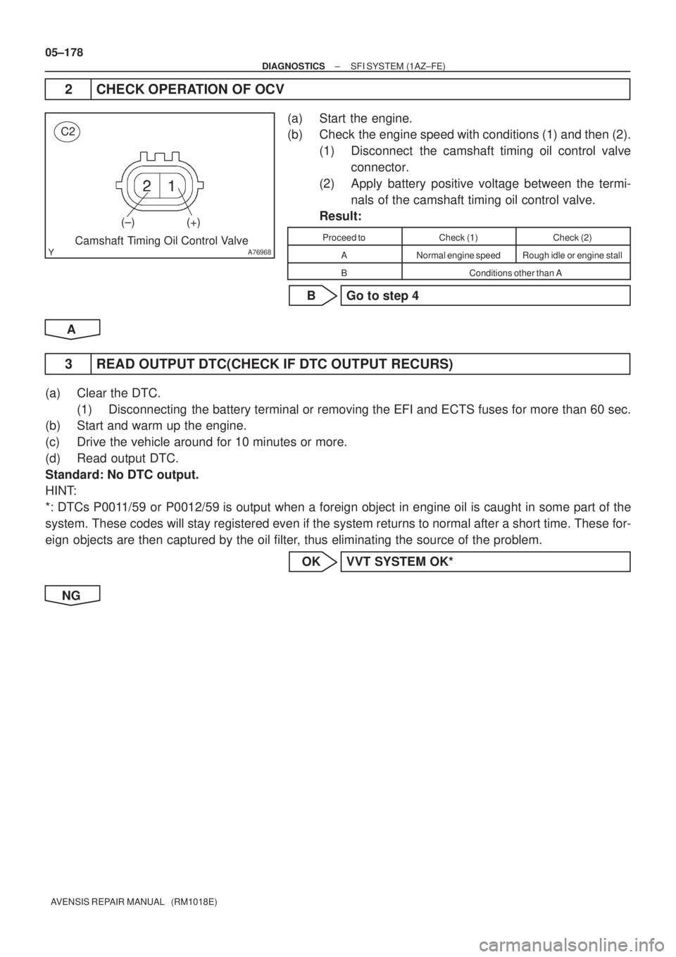
2 CHECK OPERATION OF OCV
(a) Start the engine.
(b) Check the engine speed with conditions (1) and then (2).
(1) Disconnect the camshaft timing oil control valve
connector.
(2) Apply battery positive voltage between the termi-
nals of the camshaft timing oil control valve.
Result:
Proceed toCheck (1)Check (2)
ANormal engine speedRough idle or engine stall
BConditions other than A
B Go to step 4
A
3 READ OUTPUT DTC(CHECK IF DTC OUTPUT RECURS)
(a) Clear the DTC.
(1) Disconnecting the battery terminal or removing the EFI and ECTS fuses for more than 60 sec.
(b) Start and warm up the engine.
(c) Drive the vehicle around for 10 minutes or more.
(d) Read output DTC.
Standard: No DTC output.
HINT:
*: DTCs P0011/59 or P0012/59 is output when a foreign object in engine oil is caught in some part of the
system. These codes will stay registered even if the system returns to normal after a short time. These for-
eign objects are then captured by the oil filter, thus eliminating the source of the problem.
OK VVT SYSTEM OK*
NG
Page 3883 of 5135
05±180
±
DIAGNOSTICS SFI SYSTEM(1AZ±FE)
AVENSIS REPAIR MANUAL (RM1018E)
9REPLACE CAMSHAFT TIMING GEAR ASSY
GO
10CHECK FOR BLOCKAGE(OCV, OIL CHECK VALVE AND OIL HOLE)
NGREPAIR OR REPLACE
OK
11READ OUTPUT DTC(CHECK IF DTC OUTPUT RECURS)
(a)Clear the DTC. (1)Disconnecting the battery terminal or removing the EFI and ECTS fuses for more than 6\
0 sec.
(b)Start and warm up the engine.
(c)Drive the vehicle around for 10 minutes or more.
(d)Read output DTC.
Standard: No DTC output.
HINT:
*: DTCs P0011/59 or P0012/59 is output when a foreign object in engine oil is caught in some part of \
the
system. These codes will stay registered even if the system returns to normal a\
fter a short time. These for-
eign objects are then captured by the oil filter, thus eliminating the source of the problem.
OKVVT SYSTEM OK*
NG
CHECK AND REPLACE ECM (See page 01±32)
Page 4020 of 5135

A09496
A09497
A08026
A85943
14−46− ENGINE MECHANICALCYLINDER BLOCK ASSY (1CD−FTV)(From September,
2003)
1CD−FTV ENGINE REPAIR MANUAL (RM1046E)
5. INSPECT CRANKSHAFT THRUST CLEARANCE
(a) Using a dial indicator, measure the thrust clearance while
prying the crankshaft back and forth with a screwdriver.
Standard thrust clearance:
0.040 to 0.300 mm (0.0016 to 0.0118 in.)
If the thrust clearance is greater than maximum, replace the
thrust washer as a set.
Thrust washer thickness:
Standard2.680 to 2.730 mm (0.1055 to 0.1075 in.)
Oversize 0.1252.743 to 2.793 mm (0.1080 to 0.1100 in.)
Oversize 0.2502.805 to 2.855 mm (0.1104 to 0.1124 in.)
6. REMOVE CRANKSHAFT
(a) Uniformly loosen and remove the 10 main bearing cap
bolts.
(b) Using the removed main bearing cap bolts, wiggle the cap
back and forth, then remove the 5 main bearing caps, 5
lower bearings and 2 lower thrust washers (the No. 3 main
bearing cap only).
HINT:
SKeep the lower bearing and main bearing cap together.
SArrange the main bearing caps and lower thrust washers
in the correct order.
(c) Lift the crankshaft out.
HINT:
Keep the upper bearing and upper thrust washers together with
the cylinder block.
7. REMOVE SUB−ASSY OIL NOZZLE NO.1
(a) Remove the 4 bolts and 4 oil nozzles.
Page 4040 of 5135

031H2−02
03−14
− SERVICE SPECIFICATIONSENGINE MECHANICAL
AVENSIS Supplement (RM1045E)
TORQUE SPECIFICATION
2AZ−FSE:
Part TightenedN�mkgf�cmft�lbf
Front wheel RH1031,05076
Drain plug (M/T)4950036
Engine hanger No.1 x Cylinder head3838728
Engine hanger No.2 x Cylinder head3838728
Engine coolant temperature sensor x Cylinder head2020815
Knock sensor x Cylinder block2020815
Engine oil pressure switch assy x Cylinder head1515311
Water by−pass pipe No.1 x Cylinder block9.09280 in.�lbf
Water by−pass pipe No. 3 x Cylinder block9.09280 in.�lbf
Oil cooler pipe x Cylinder block9.09280 in.�lbf
Drive shaft bearing bracket x Cylinder block5455140
Oil level gauge guide x Cylinder block9.09280 in.�lbf
V−ribbed belt tensioner assy x Timing chain cover6060744
Ignition coil assy x Cylinder head9.09280 in.�lbf
Water inlet x Cylinder block9.09280 in.�lbf
Exhaust manifold converter x Cylinder head3737827
Exhaust manifold stay x Exhaust manifold converter4444932
Exhaust manifold heat insulator No. 1 x Exhaust manifold converter121229
Surge tank stay No. 1 x Intake manifold2121015
Intake manifold x Cylinder head3030622
Throttle Body bracket x Throttle body2121015
Drive plate & ring gear x Crankshaft981,00072
Transverse engine engine mounting bracket front x Transverse engine en-
gine mounting insulator front8788764
Transverse engine engine mounting bracket rear x Transverse engine engine
mounting insulator rear8788764
Front suspension cross member sub−assy front x Body Bolt
Nut45
133459
1,35633
98
Front suspension brace RH x Frame Bolt A
Bolt B133
801,356
81698
59
Front suspension brace LH x Frame Bolt A
Bolt B133
801,356
81698
59
Transverse engine engine mounting insulator LH x Engine mounting bracket
LH8788764
Transverse engine engine mounting insulator RH x Engine mounting bracket
RH5253038
Engine mounting bracket x No. 2 RH x Transverse engine
engine mounting insulator A
B
52
11 3530
1,15238
83
Vane pump assy x Timing chain cover3737027
Front suspension arm sub−assy lower No. 1 x Lower ball joint1271,29694
Front stabilizer link assy x Front suspension7475555
Floor panel brace front x Floor3030622
Engine service cover bracket RH x Body RHD steering position type9.09280 in.�lbf
Cooler bracket x Body LHD steering position type9.09280 in.�lbf
Oil reservoir bracket No. 1 x Body8.08271 in.�lbf
Return tube sub−assy x Frame8.08271 in.�lbf
Radiator reserve tank Sub−assy x Body5.05144 in.�lbf
Compressor and magnetic clutch x Cylinder block2525518
Radiator relay block x Frame5.05144 in.�lbf