Page 3712 of 5135

A36647
A13478
A01178
A01179
A13851
14±44
± ENGINE MECHANICALCYLINDER BLOCK (1AZ±FE)
1AZ±FE ENGINE REPAIR MANUAL (RM865E)
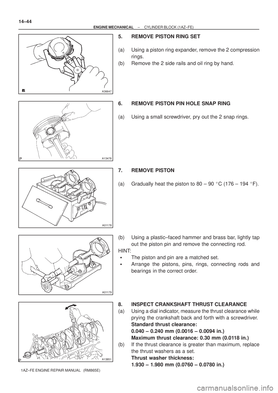
5. REMOVE PISTON RING SET
(a) Using a piston ring expander, remove the 2 compression
rings.
(b) Remove the 2 side rails and oil ring by hand.
6. REMOVE PISTON PIN HOLE SNAP RING
(a) Using a small screwdriver, pry out the 2 snap rings.
7. REMOVE PISTON
(a) Gradually heat the piston to 80 ± 90 �C (176 ± 194 �F).
(b) Using a plastic±faced hammer and brass bar, lightly tap
out the piston pin and remove the connecting rod.
HINT:
�The piston and pin are a matched set.
�Arrange the pistons, pins, rings, connecting rods and
bearings in the correct order.
8. INSPECT CRANKSHAFT THRUST CLEARANCE
(a) Using a dial indicator, measure the thrust clearance while
prying the crankshaft back and forth with a screwdriver.
Standard thrust clearance:
0.040 ± 0.240 mm (0.0016 ± 0.0094 in.)
Maximum thrust clearance: 0.30 mm (0.0118 in.)
(b) If the thrust clearance is greater than maximum, replace
the thrust washers as a set.
Thrust washer thickness:
1.930 ± 1.980 mm (0.0760 ± 0.0780 in.)
Page 3744 of 5135

C69531
C69798
C69534
C69535
± MANUAL TRANSMISSION/TRANSAXLESHIFT & SELECT LEVER SHAFT ASSY (E355/E356)
41±73
E355,E356 M/T REPAIR MANUAL (RM867E)
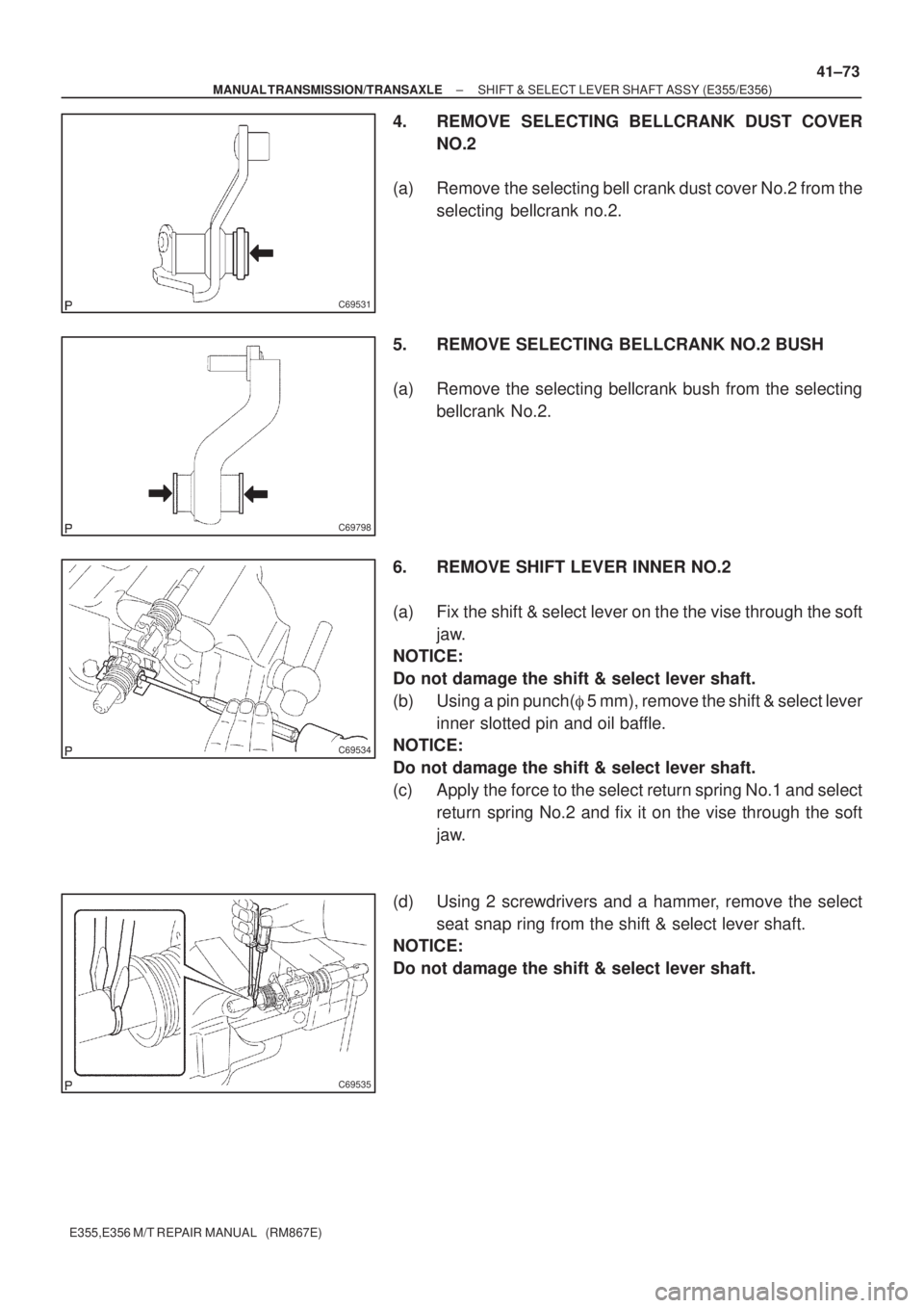
4. REMOVE SELECTING BELLCRANK DUST COVER
NO.2
(a) Remove the selecting bell crank dust cover No.2 from the
selecting bellcrank no.2.
5. REMOVE SELECTING BELLCRANK NO.2 BUSH
(a) Remove the selecting bellcrank bush from the selecting
bellcrank No.2.
6. REMOVE SHIFT LEVER INNER NO.2
(a) Fix the shift & select lever on the the vise through the soft
jaw.
NOTICE:
Do not damage the shift & select lever shaft.
(b) Using a pin punch(� 5 mm), remove the shift & select lever
inner slotted pin and oil baffle.
NOTICE:
Do not damage the shift & select lever shaft.
(c) Apply the force to the select return spring No.1 and select
return spring No.2 and fix it on the vise through the soft
jaw.
(d) Using 2 screwdrivers and a hammer, remove the select
seat snap ring from the shift & select lever shaft.
NOTICE:
Do not damage the shift & select lever shaft.
Page 3745 of 5135
C68317
C69538
C91167
Shift inter
lock plate
cover
C91169
Shift lever
inner No.1
C69539
41±74
± MANUAL TRANSMISSION/TRANSAXLESHIFT & SELECT LEVER SHAFT ASSY (E355/E356)
E355,E356 M/T REPAIR MANUAL (RM867E)
7. REMOVE SELECT SPRING SEAT NO.1
(a) Using a pin punch(� 5 mm), remove the shift inner lever
slotted pin from the shift & select lever shaft.
(b) Remove the shift lever assy select return spring No.1 and
select spring seat from the shift & select lever shaft.
8. REMOVE SHIFT INTER LOCK PLATE COVER
(a) Remove the shift inter lock plate cover from the shift inter
lock plate.
9. REMOVE SHIFT LEVER INNER NO.1
(a) Remove the shift lever inner No.1 from the shift inter lock
plate.
10. REMOVE SELECT SPRING NO.1 SEAT SHAFT SNAP
RING
(a) Using 2 screwdrivers and a hammer, remove the select
spring No.1 seat shaft snap ring.
NOTICE:
Do not damage the shaft.
Page 3750 of 5135
C69639
SST
C69640
C69641
SST
C69642
41±62
± MANUAL TRANSMISSION/TRANSAXLEOUTPUT SHAFT ASSY (E355/E356)
E355,E356 M/T REPAIR MANUAL (RM867E)
4. INSPECT 2ND GEAR RADIAL CLEARANCE
(a) Using a dial indicator, measure the 2nd gear radial clear-
ance.
Standard clearance:mm (in.)
BearingStandard clearance
KOYO made0.009 ± 0.053
(0.0004 ± 0.0021)
NSK made0.009 ± 0.051
(0.0004 ± 0.0020)
If the clearance is out of the specification, replace the 2nd gear
needle roller bearing.
5. REMOVE 4TH DRIVEN GEAR
(a) Using SST and a press, remove the output shaft bearing
rear (inner race) and 4th driven gear.
SST 09950±00020
6. REMOVE OUTPUT GEAR SPACER
(a) Remove the out put gear spacer from the output shaft.
7. REMOVE 2ND GEAR
(a) Using SST and a press, remove the 3rd driven gear and
2nd gear from the out put shaft.
SST 09950±00020
Page 3755 of 5135

C70507
C69671
C69672
SST
C69674
± MANUAL TRANSMISSION/TRANSAXLEOUTPUT SHAFT ASSY (E355/E356)
41±67
E355,E356 M/T REPAIR MANUAL (RM867E)
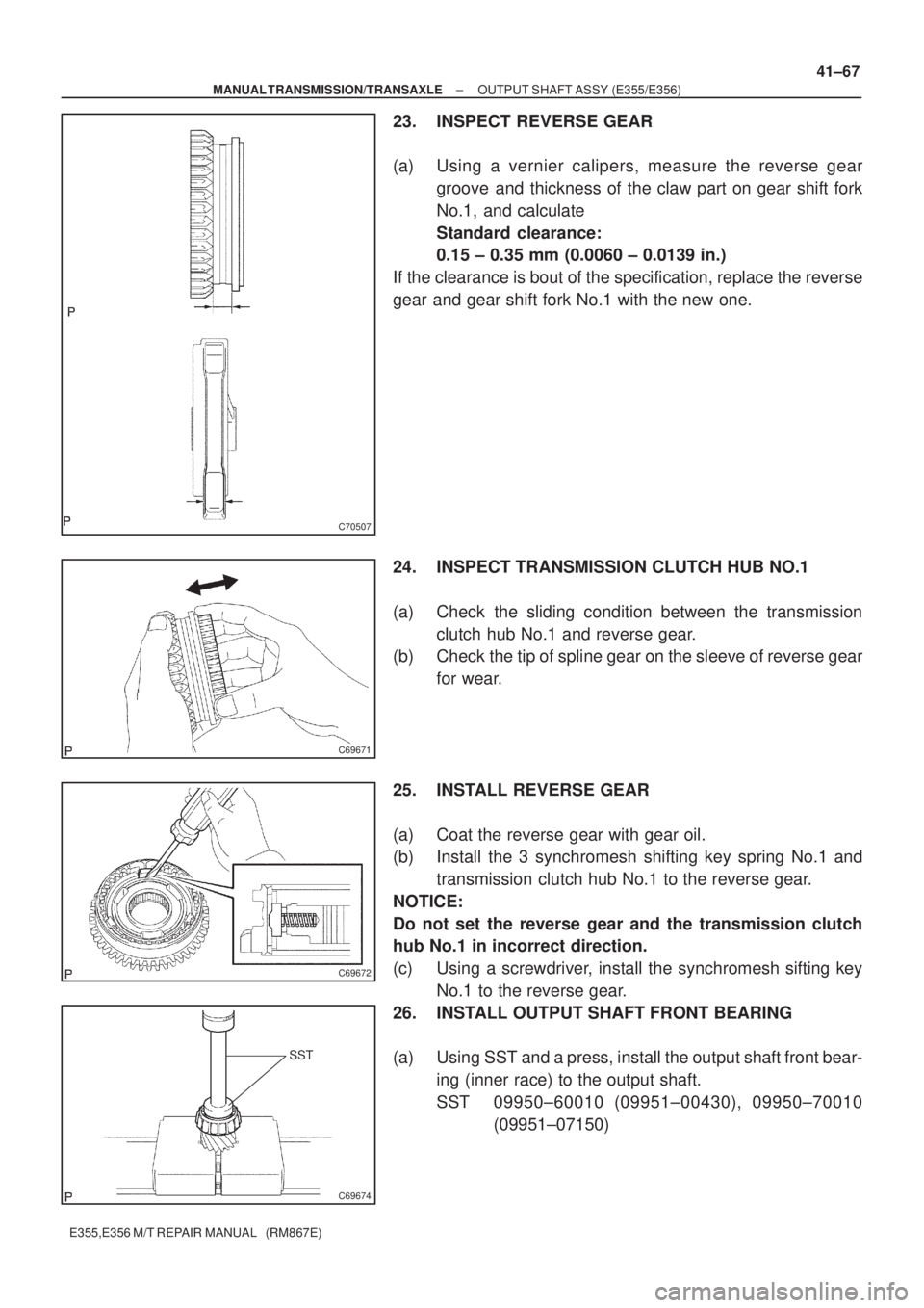
23. INSPECT REVERSE GEAR
(a) Using a vernier calipers, measure the reverse gear
groove and thickness of the claw part on gear shift fork
No.1, and calculate
Standard clearance:
0.15 ± 0.35 mm (0.0060 ± 0.0139 in.)
If the clearance is bout of the specification, replace the reverse
gear and gear shift fork No.1 with the new one.
24. INSPECT TRANSMISSION CLUTCH HUB NO.1
(a) Check the sliding condition between the transmission
clutch hub No.1 and reverse gear.
(b) Check the tip of spline gear on the sleeve of reverse gear
for wear.
25. INSTALL REVERSE GEAR
(a) Coat the reverse gear with gear oil.
(b) Install the 3 synchromesh shifting key spring No.1 and
transmission clutch hub No.1 to the reverse gear.
NOTICE:
Do not set the reverse gear and the transmission clutch
hub No.1 in incorrect direction.
(c) Using a screwdriver, install the synchromesh sifting key
No.1 to the reverse gear.
26. INSTALL OUTPUT SHAFT FRONT BEARING
(a) Using SST and a press, install the output shaft front bear-
ing (inner race) to the output shaft.
SST 09950±60010 (09951±00430), 09950±70010
(09951±07150)
Page 3758 of 5135
SST
SST
C69676
C69641
SST
SST
C69677
SST
SST
C69678
41±70
± MANUAL TRANSMISSION/TRANSAXLEOUTPUT SHAFT ASSY (E355/E356)
E355,E356 M/T REPAIR MANUAL (RM867E)
37. INSTALL 3RD DRIVEN GEAR
(a) Using SST and a press, install the 3rd driven gear to the
output shaft.
SST 09608±00071, 09950±60010 (09951±00320),
09950±70010 (09951±07100)
38. INSTALL OUTPUT GEAR SPACER
(a) install the output gear spacer to the output shaft.
39. INSTALL 4TH DRIVEN GEAR
(a) Using SST and a press, install the 4th driven gear to the
output shaft.
SST 09608±00071, 09950±60010 (09951±00320),
09950±70010 (09951±07100)
40. INSTALL OUTPUT SHAFT FRONT BEARING
(a) Using SST and a press, install the output shaft front bear-
ing (inner race) to the output shaft.
SST 09506±30012, 09950±60010 (09951±00320),
09950±70010 (09951±07100)
Page 3761 of 5135
C69549
C70515
SST
C69550
C69551
± MANUAL TRANSMISSION/TRANSAXLEINPUT SHAFT ASSY (E355/E356)
41±51
E355,E356 M/T REPAIR MANUAL (RM867E)
4. INSPECT 3RD GEAR RADIAL CLEARANCE
(a) Using a dial indicator, measure the 3rd gear radial clear-
ance.
Standard clearance: mm (in.)
BearingStandard clearance
KOYO made0.009 ± 0.053
(0.0004 ± 0.0021)
NSK made0.009 ± 0.051
(0.0004 ± 0.0020)
If the clearance exceeds the maximum, replace the 3rd gear
needle roller bearing.
5. REMOVE 4TH GEAR
(a) Fix the input shaft assy and soft jaws to the valse.
(b) Using a 2 screwdrivers and a hammer, remove the input
shaft rear bearing shaft snap ring from the input shaft.
NOTICE:
Using a waste to prevent the snap ring from being scat-
tered.
(c) Using SST and a press, remove the input shaft rear bear-
ing and 4th gear.
SST 09950±00020
NOTICE:
Do not tighten SST excessively.
6. REMOVE 4TH GEAR NEEDLE ROLLER BEARING
(a) Remove the 4th gear needle roller bearing from the input
shaft.
Page 3762 of 5135
C69552
C69553
C69615
SST
C69616
C69617
41±52
± MANUAL TRANSMISSION/TRANSAXLEINPUT SHAFT ASSY (E355/E356)
E355,E356 M/T REPAIR MANUAL (RM867E)
7. REMOVE 2ND SYNCHRONIZER OUTER RING
(a) Remove the 2nd synchronizer outer ring from the trans-
mission clutch hub No.2.
8. REMOVE 4TH GEAR BEARING SPACER
(a) Remove the 4th gear bearing spacer from the transmis-
sion clutch hub No.2.
9. REMOVE 3RD GEAR
(a) Using 2 screwdrivers and a hammer, remove the clutch
hub No.2 setting shaft snap ring from the input shaft.
NOTICE:
Using a waste to prevent the snap ring from being scat-
tered.
(b) Using SST and a press, remove the transmission clutch
hub No.2 and 3rd gear from the input shaft.
SST 09950±00020
NOTICE:
Do not tighten SST excessively.
10. REMOVE 3RD GEAR NEEDLE ROLLER BEARING
(a) Remove the 3rd gear needle roller bearing from the input
shaft.