Page 3646 of 5135
D03574
D03575
D03576
D09201
D08048
40±24
± AUTOMATIC TRANSMISSION / TRANSAUTOMATIC TRANSAXLE ASSY (U241E)
U241E A/T REPAIR MANUAL (RM840U)
40. REMOVE FORWARD CLUTCH ASSY
(a) Remove the forward clutch from the transaxle case.
41. REMOVE MULTIPLE DISC CLUTCH CLUTCH HUB
(a) Remove the thrust bearing, multiple clutch hub, needle
roller bearing and bearing race from the transaxle case.
42. REMOVE UNDERDRIVE PLANETARY GEAR ASSY
(a) Remove the bolt and parking pawl shaft clamp.
(b) Remove the parking lock pawl shaft.
(c) Push the parking lock pawn.
HINT:
Failure to do so will cause interference when the U/D planetary
gear is removed.
Page 3676 of 5135
C50158
D03581
D03580
D09691
D09692
40±54
± AUTOMATIC TRANSMISSION / TRANSAUTOMATIC TRANSAXLE ASSY (U241E)
U241E A/T REPAIR MANUAL (RM840U)
(c) Install the 1±way clutch to the transaxle case.
NOTICE:
Make sure that the mark on the 1±way clutch outer race is
visible.
(d) Using screwdriver, install the snap ring to the transaxle
case.
104. INSTALL UNDERDRIVE CLUTCH ASSY
(a) Coat the bearing and bearing race with petroleum jelly,
install them onto the U/D clutch.
Race diameter: mm (in.)
InsideOutside
Bearing37.73 (1.4854)58.0 (2.283)
Race29.9 (1.177)55.5 (2.185)
(b) Install the U/D clutch assy to the transaxle case.
105. INSTALL UNDERDRIVE PLANETARY GEAR ASSY
(a) Install the parking lock pawl pin and torsion spring to the
parking lock pawl.
(b) Temporarily install the parking lock pawl, shaft and spring
to the transaxle case as shown in the illustration.
Page 3677 of 5135

D03579
D09693
D03576
D03875
D
D25511
Dimension (1)
Dimension (2)
± AUTOMATIC TRANSMISSION / TRANSAUTOMATIC TRANSAXLE ASSY (U241E)
40±55
U241E A/T REPAIR MANUAL (RM840U)
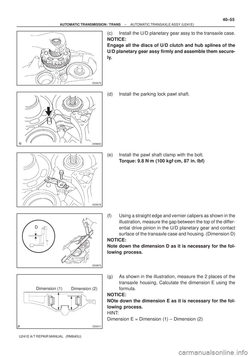
(c) Install the U/D planetary gear assy to the transaxle case.
NOTICE:
Engage all the discs of U/D clutch and hub splines of the
U/D planetary gear assy firmly and assemble them secure-
ly.
(d) Install the parking lock pawl shaft.
(e) Install the pawl shaft clamp with the bolt.
Torque: 9.8 N�m (100 kgf�cm, 87 in.�lbf)
(f) Using a straight edge and vernier calipers as shown in the
illustration, measure the gap between the top of the differ-
ential drive pinion in the U/D planetary gear and contact
surface of the transaxle case and housing. (Dimension D)
NOTICE:
Note down the dimension D as it is necessary for the fol-
lowing process.
(g) As shown in the illustration, measure the 2 places of the
transaxle housing, Calculate the dimension E using the
formula.
NOTICE:
NOte down the dimension E as it is necessary for the fol-
lowing process.
HINT:
Dimension E = Dimension (1) ± Dimension (2)
Page 3679 of 5135

D11358
Race ”B”
Race ”A”
Forward Clutch Side
D03574
D03573
C50035
D03569
−
AUTOMATIC TRANSMISSION / TRANS AUTOMATIC TRANSAXLE ASSY (U24
1E)
40− 57
Correction to R/M Pub. No. RM840U (Bulletin No. OB −1123)
108. INSTALL FORWARD CLUTCH ASSY
(a) Install the input shaft thrust bearing to the forward clutch.
Bearing diameter: mm (in.)
InsideOutside
Bearing33.85 ( 1.3327)52.2 (2.055)
NOTICE:
Install the thrust bearing properly so that the race ”B” will
be visible.
(b) Install the forward clutch to the multiple clutch hub.
NOTICE:
Align the splines of all discs in the forward clutch with
those of multiple clutch hub to assemble them securely.
109. INSTALL OVERDRIVE BRAKE GASKET
[35179 / 98− 3]
(a) Install 2 new O/D brake gaskets to the transaxle case.
11 0. INSTALL FRONNT DIFFERENTIAL ASSY
(a) Install the differential assy to the transaxle case.
111 . INSTALL OIL PUMP ASSEMBLY
(a) Install the oil pump assy and 7 bolts to the transaxle case.
Torque: 22 N ⋅m (226 kgf⋅cm, 16ft⋅lbf)
Page 3680 of 5135

D25506
D25505
D03915
40±58
± AUTOMATIC TRANSMISSION / TRANSAUTOMATIC TRANSAXLE ASSY (U241E)
U241E A/T REPAIR MANUAL (RM840U)
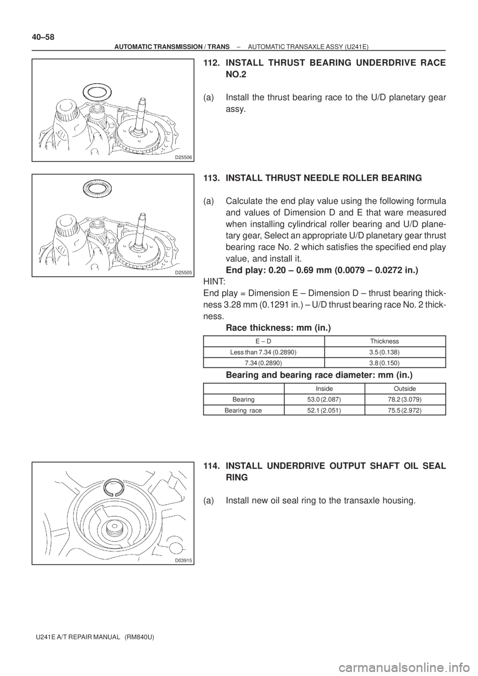
112. INSTALL THRUST BEARING UNDERDRIVE RACE
NO.2
(a) Install the thrust bearing race to the U/D planetary gear
assy.
113. INSTALL THRUST NEEDLE ROLLER BEARING
(a) Calculate the end play value using the following formula
and values of Dimension D and E that ware measured
when installing cylindrical roller bearing and U/D plane-
tary gear, Select an appropriate U/D planetary gear thrust
bearing race No. 2 which satisfies the specified end play
value, and install it.
End play: 0.20 ± 0.69 mm (0.0079 ± 0.0272 in.)
HINT:
End play = Dimension E ± Dimension D ± thrust bearing thick-
ness 3.28 mm (0.1291 in.) ± U/D thrust bearing race No. 2 thick-
ness.
Race thickness: mm (in.)
E ± DThickness
Less than 7.34 (0.2890)3.5 (0.138)
7.34 (0.2890)3.8 (0.150)
Bearing and bearing race diameter: mm (in.)
InsideOutside
Bearing53.0 (2.087)78.2 (3.079)
Bearing race52.1 (2.051)75.5 (2.972)
114. INSTALL UNDERDRIVE OUTPUT SHAFT OIL SEAL
RING
(a) Install new oil seal ring to the transaxle housing.
Page 3683 of 5135

D03564
D03930
D03559
D03561
D03560
B
A
± AUTOMATIC TRANSMISSION / TRANSAUTOMATIC TRANSAXLE ASSY (U241E)
40±61
U241E A/T REPAIR MANUAL (RM840U)
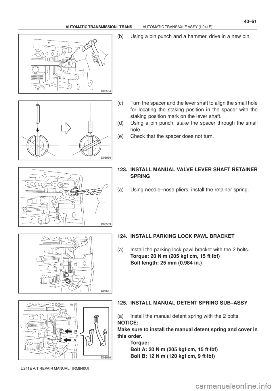
(b) Using a pin punch and a hammer, drive in a new pin.
(c) Turn the spacer and the lever shaft to align the small hole
for locating the staking position in the spacer with the
staking position mark on the lever shaft.
(d) Using a pin punch, stake the spacer through the small
hole.
(e) Check that the spacer does not turn.
123. INSTALL MANUAL VALVE LEVER SHAFT RETAINER
SPRING
(a) Using needle±nose pliers, install the retainer spring.
124. INSTALL PARKING LOCK PAWL BRACKET
(a) Install the parking lock pawl bracket with the 2 bolts.
Torque: 20 N�m (205 kgf�cm, 15 ft�lbf)
Bolt length: 25 mm (0.984 in.)
125. INSTALL MANUAL DETENT SPRING SUB±ASSY
(a) Install the manual detent spring with the 2 bolts.
NOTICE:
Make sure to install the manual detent spring and cover in
this order.
Torque:
Bolt A: 20 N�m (205 kgf�cm, 15 ft�lbf)
Bolt B: 12 N�m (120 kgf�cm, 9 ft�lbf)
Page 3690 of 5135
D08094
D09642
D08033
D08032
40±68
± AUTOMATIC TRANSMISSION / TRANSAUTOMATIC TRANSAXLE ASSY (U241E)
U241E A/T REPAIR MANUAL (RM840U)
(d) Turn the lever counterclockwise until it stops, and then
turn it clockwise 2 notches.
(e) Remove the control shaft lever.
(f) Align the groove with neutral basic line.
(g) Tighten the 2 bolts.
Torque: 5.4 N�m (55 kgf�cm, 48 in.�lbf)
(h) Using a screwdriver, stake the nut with the nut stopper.
(i) Install the control shaft lever, washer and nut.
Torque: 13 N�m (133 kgf�cm, 10 ft�lbf)
145. INSTALL SPEEDOMETER DRIVEN HOLE (ATM) COVER SUB±ASSY
(a) Coat the new O±ring with ATF and install it to the speedometer driven hole cover.
(b) Install the bolt and speedometer driven hole cover sub±assy to the transaxle assy.
Torque: 7.0 N�m (70 kgf�cm, 61 in.�lbf)
Page 3702 of 5135

D25212
SST
D25213
SST
D25214
SST
C59843
C59998
± AUTOMATIC TRANSMISSION / TRANSFRONT DIFFERENTIAL ASSY (U241E)
40±101
U241E A/T REPAIR MANUAL (RM840U)
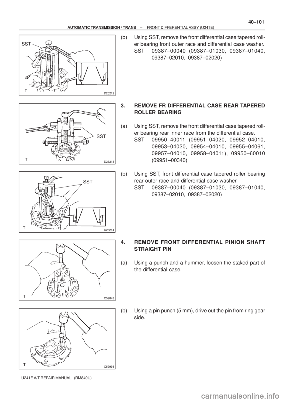
(b) Using SST, remove the front differential case tapered roll-
er bearing front outer race and differential case washer.
SST 09387±00040 (09387±01030, 09387±01040,
09387±02010, 09387±02020)
3. REMOVE FR DIFFERENTIAL CASE REAR TAPERED
ROLLER BEARING
(a) Using SST, remove the front differential case tapered roll-
er bearing rear inner race from the differential case.
SST 09950±40011 (09951±04020, 09952±04010,
09953±04020, 09954±04010, 09955±04061,
09957±04010, 09958±04011), 09950±60010
(09951±00340)
(b) Using SST, front differential case tapered roller bearing
rear outer race and differential case washer.
SST 09387±00040 (09387±01030, 09387±01040,
09387±02010, 09387±02020)
4. REMOVE FRONT DIFFERENTIAL PINION SHAFT
STRAIGHT PIN
(a) Using a punch and a hummer, loosen the staked part of
the differential case.
(b) Using a pin punch (5 mm), drive out the pin from ring gear
side.