Page 2863 of 5135
C65369
D30331
Cloth
F09875
������D30332
LengthThickness
R10282
Feeler Gauge
± POWER STEERINGVANE PUMP ASSY (1CD±FTV)
51±21
AVENSIS REPAIR MANUAL (RM1018E)
(c) Remove the O±ring from the housing sub±assy front.
14. REMOVE VANE PUMP HOUSING OIL SEAL
(a) Using a screwdriver, remove the housing oil seal.
NOTICE:
Be careful not to damage the pump housing.
15. INSPECT VANE PUMP SHAFT AND BUSH IN
HOUSING FRONT
(a) Using a micrometer and a caliper gauge, measure the oil
clearance.
Maximum clearance: 0.07 mm (0.0028 in.)
If it is more than the maximum, replace the vane pump assy.
16. INSPECT VANE PUMP ROTOR AND VANE PUMP
PLATES
(a) Using a micrometer, measure the thickness of the vane
pump plates.
Minimum thickness:
1.405 to 1.411 mm (0.05531 to 0.05555 in.)
(b) Using a feeler gauge, measure the clearance between a
side face of the vane pump rotor groove and vane plate.
Maximum clearance: 0.03 mm (0.0012 in.)
Page 2867 of 5135
������D30335
Inward
Outward
������D30336
C70126
F45776
Service Bolt
± POWER STEERINGVANE PUMP ASSY (1CD±FTV)
51±25
AVENSIS REPAIR MANUAL (RM1018E)
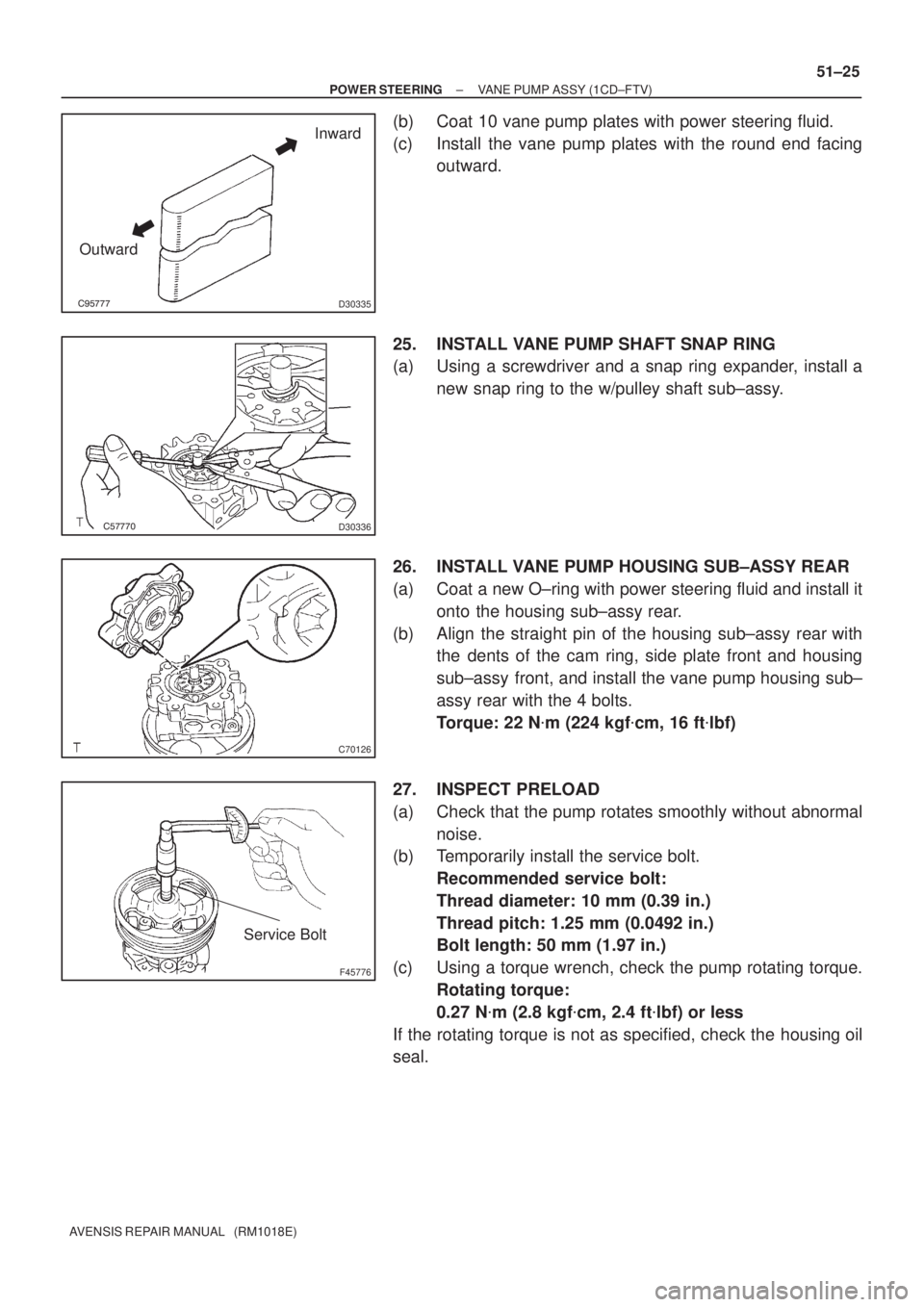
(b) Coat 10 vane pump plates with power steering fluid.
(c) Install the vane pump plates with the round end facing
outward.
25. INSTALL VANE PUMP SHAFT SNAP RING
(a) Using a screwdriver and a snap ring expander, install a
new snap ring to the w/pulley shaft sub±assy.
26. INSTALL VANE PUMP HOUSING SUB±ASSY REAR
(a) Coat a new O±ring with power steering fluid and install it
onto the housing sub±assy rear.
(b) Align the straight pin of the housing sub±assy rear with
the dents of the cam ring, side plate front and housing
sub±assy front, and install the vane pump housing sub±
assy rear with the 4 bolts.
Torque: 22 N�m (224 kgf�cm, 16 ft�lbf)
27. INSPECT PRELOAD
(a) Check that the pump rotates smoothly without abnormal
noise.
(b) Temporarily install the service bolt.
Recommended service bolt:
Thread diameter: 10 mm (0.39 in.)
Thread pitch: 1.25 mm (0.0492 in.)
Bolt length: 50 mm (1.97 in.)
(c) Using a torque wrench, check the pump rotating torque.
Rotating torque:
0.27 N�m (2.8 kgf�cm, 2.4 ft�lbf) or less
If the rotating torque is not as specified, check the housing oil
seal.
Page 2871 of 5135
F42475
C84483
C57767
51±10
± POWER STEERINGVANE PUMP ASSY (AZ Series)
AVENSIS REPAIR MANUAL (RM1018E)
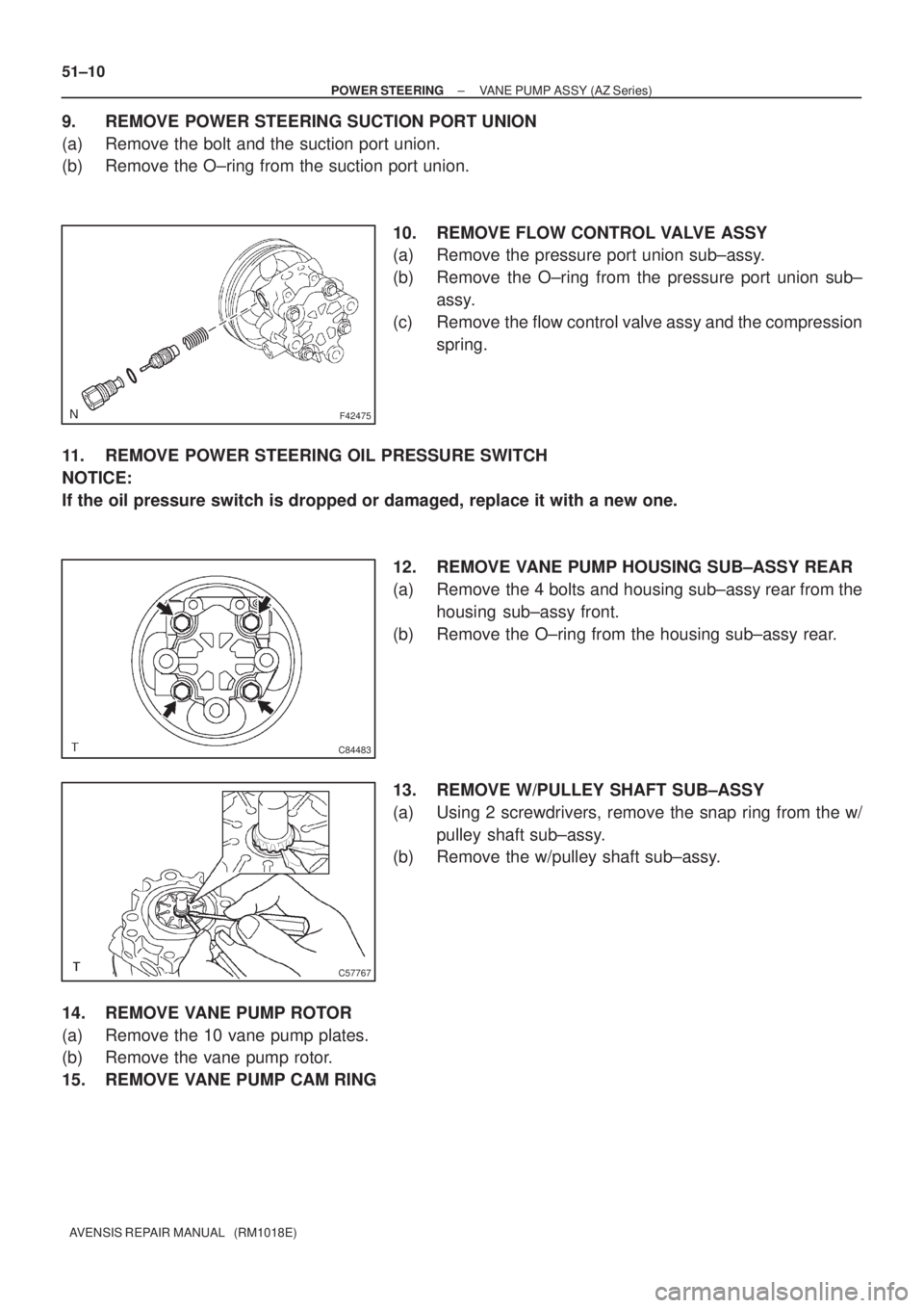
9. REMOVE POWER STEERING SUCTION PORT UNION
(a) Remove the bolt and the suction port union.
(b) Remove the O±ring from the suction port union.
10. REMOVE FLOW CONTROL VALVE ASSY
(a) Remove the pressure port union sub±assy.
(b) Remove the O±ring from the pressure port union sub±
assy.
(c) Remove the flow control valve assy and the compression
spring.
11. REMOVE POWER STEERING OIL PRESSURE SWITCH
NOTICE:
If the oil pressure switch is dropped or damaged, replace it with a new one.
12. REMOVE VANE PUMP HOUSING SUB±ASSY REAR
(a) Remove the 4 bolts and housing sub±assy rear from the
housing sub±assy front.
(b) Remove the O±ring from the housing sub±assy rear.
13. REMOVE W/PULLEY SHAFT SUB±ASSY
(a) Using 2 screwdrivers, remove the snap ring from the w/
pulley shaft sub±assy.
(b) Remove the w/pulley shaft sub±assy.
14. REMOVE VANE PUMP ROTOR
(a) Remove the 10 vane pump plates.
(b) Remove the vane pump rotor.
15. REMOVE VANE PUMP CAM RING
Page 2872 of 5135
C65368
C65369
D30331
Cloth
F09875
������D30332
LengthThickness
± POWER STEERINGVANE PUMP ASSY (AZ Series)
51±11
AVENSIS REPAIR MANUAL (RM1018E)
16. REMOVE VANE PUMP SIDE PLATE FRONT
(a) Remove the side plate front from the housing sub±assy
front.
(b) Remove the O±ring from the side plate front.
(c) Remove the O±ring from the housing sub±assy front.
17. REMOVE VANE PUMP HOUSING OIL SEAL
(a) Using a screwdriver, remove the housing oil seal.
NOTICE:
Be careful not to damage the pump housing.
18. INSPECT VANE PUMP SHAFT AND BUSH IN
HOUSING FRONT
(a) Using a micrometer and a caliper gauge, measure the oil
clearance.
Maximum clearance: 0.07 mm (0.0028 in.)
If it is more than the maximum, replace the vane pump assy.
19. INSPECT VANE PUMP ROTOR AND VANE PUMP
PLATES
(a) Using a micrometer, measure the thickness of the vane
pump plates.
Minimum thickness:
1.405 to 1.411 mm (0.05531 to 0.05555 in.)
Page 2876 of 5135
������D30335
Inward
Outward
������D30336
C70126
C53369
Service Bolt
± POWER STEERINGVANE PUMP ASSY (AZ Series)
51±15
AVENSIS REPAIR MANUAL (RM1018E)
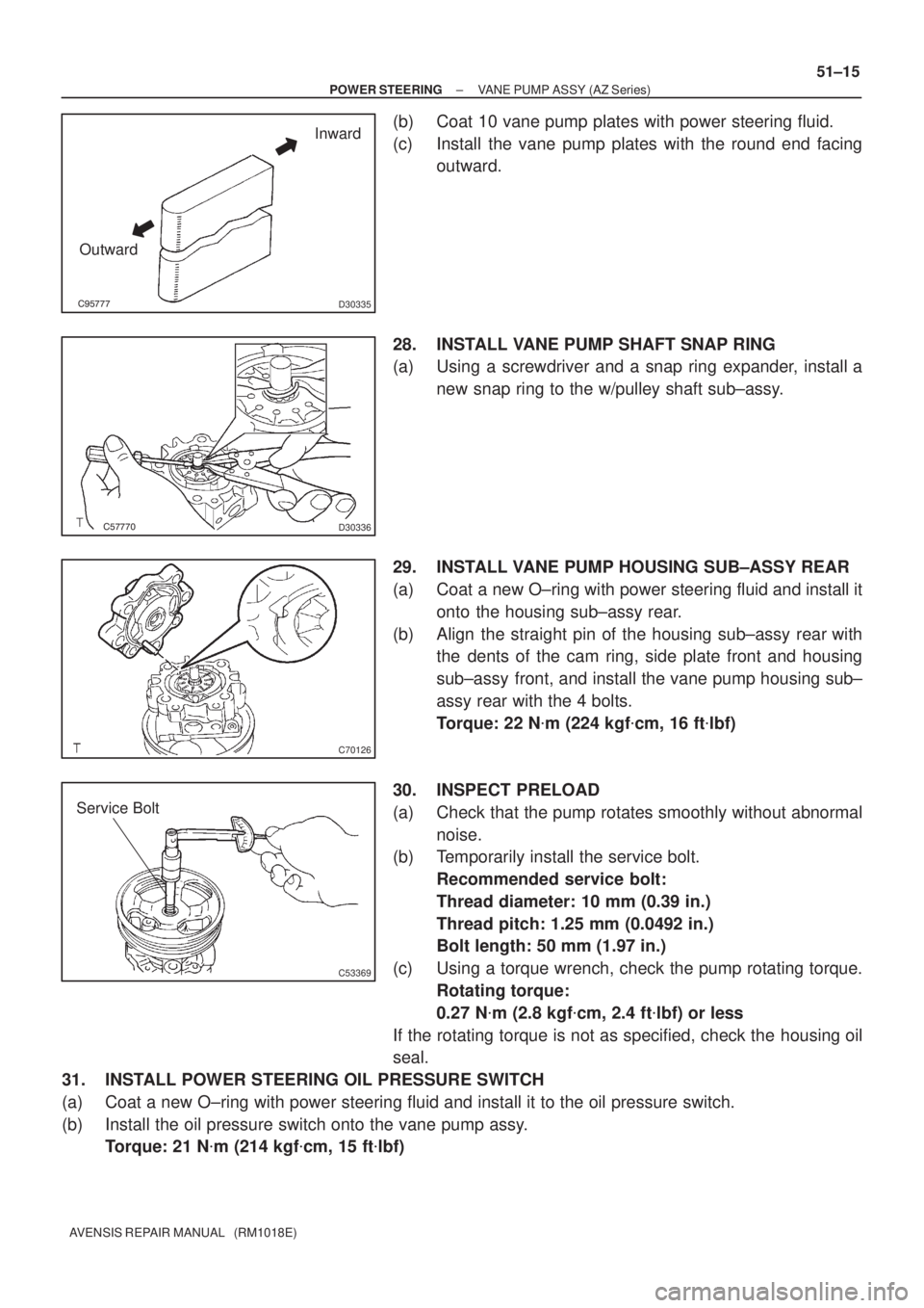
(b) Coat 10 vane pump plates with power steering fluid.
(c) Install the vane pump plates with the round end facing
outward.
28. INSTALL VANE PUMP SHAFT SNAP RING
(a) Using a screwdriver and a snap ring expander, install a
new snap ring to the w/pulley shaft sub±assy.
29. INSTALL VANE PUMP HOUSING SUB±ASSY REAR
(a) Coat a new O±ring with power steering fluid and install it
onto the housing sub±assy rear.
(b) Align the straight pin of the housing sub±assy rear with
the dents of the cam ring, side plate front and housing
sub±assy front, and install the vane pump housing sub±
assy rear with the 4 bolts.
Torque: 22 N�m (224 kgf�cm, 16 ft�lbf)
30. INSPECT PRELOAD
(a) Check that the pump rotates smoothly without abnormal
noise.
(b) Temporarily install the service bolt.
Recommended service bolt:
Thread diameter: 10 mm (0.39 in.)
Thread pitch: 1.25 mm (0.0492 in.)
Bolt length: 50 mm (1.97 in.)
(c) Using a torque wrench, check the pump rotating torque.
Rotating torque:
0.27 N�m (2.8 kgf�cm, 2.4 ft�lbf) or less
If the rotating torque is not as specified, check the housing oil
seal.
31. INSTALL POWER STEERING OIL PRESSURE SWITCH
(a) Coat a new O±ring with power steering fluid and install it to the oil pressure switch.
(b) Install the oil pressure switch onto the vane pump assy.
Torque: 21 N�m (214 kgf�cm, 15 ft�lbf)
Page 2891 of 5135
550YP±01
I31981
Bolt B
Nut A
I31981
I31981
Bolt B
Nut A
Measuring
Position
F11928
CORRECT WRONG WRONG 55±46
± HEATER & AIR CONDITIONERV (COOLER COMPRESSOR TO CRANKSHAFT
PULLEY) BELT NO.1
AVENSIS REPAIR MANUAL (RM1018E)
V (COOLER COMPRESSOR TO CRANKSHAFT PULLEY)
BELT NO.1
REPLACEMENT
1. REMOVE RADIATOR SUPPORT OPENING COVER
2. REMOVE ENGINE ROOM COVER SIDE
3. REMOVE ENGINE UNDER COVER RH
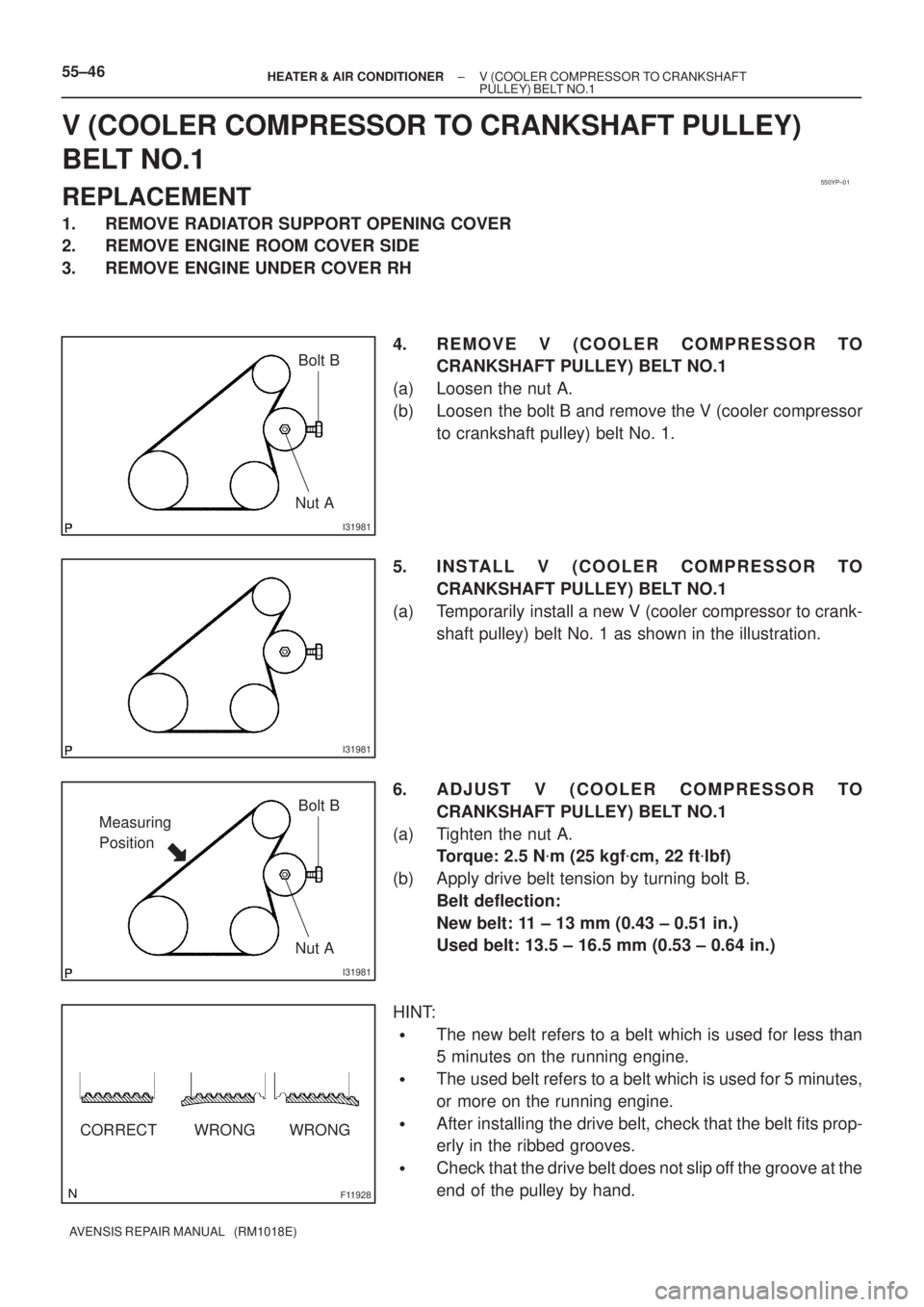
4. REMOVE V (COOLER COMPRESSOR TO
CRANKSHAFT PULLEY) BELT NO.1
(a) Loosen the nut A.
(b) Loosen the bolt B and remove the V (cooler compressor
to crankshaft pulley) belt No. 1.
5. INSTALL V (COOLER COMPRESSOR TO
CRANKSHAFT PULLEY) BELT NO.1
(a) Temporarily install a new V (cooler compressor to crank-
shaft pulley) belt No. 1 as shown in the illustration.
6. ADJUST V (COOLER COMPRESSOR TO
CRANKSHAFT PULLEY) BELT NO.1
(a) Tighten the nut A.
Torque: 2.5 N�m (25 kgf�cm, 22 ft�lbf)
(b) Apply drive belt tension by turning bolt B.
Belt deflection:
New belt: 11 ± 13 mm (0.43 ± 0.51 in.)
Used belt: 13.5 ± 16.5 mm (0.53 ± 0.64 in.)
HINT:
�The new belt refers to a belt which is used for less than
5 minutes on the running engine.
�The used belt refers to a belt which is used for 5 minutes,
or more on the running engine.
�After installing the drive belt, check that the belt fits prop-
erly in the ribbed grooves.
�Check that the drive belt does not slip off the groove at the
end of the pulley by hand.
Page 3458 of 5135
022KC±01
± PREPARATIONSTARTING & CHARGING
02±5
1AZ±FSE ENGINE REPAIR MANUAL (RM1019E)
STARTING & CHARGING
PREPARATION
SST
09285±76010Injection Pump Camshaft Bearing
Cone ReplacerGENERATOR ASSY
Recomended Tools
09041±00020Torx Driver T25STARTER ASSY
09904±00010Expander SetSTARTER ASSY
(09904±00050)No. 4 ClawSTARTER ASSY
Equipment
Dial indicator
Ohmmeter
Torque wrench
Slide calipers
V±block
Page 3463 of 5135
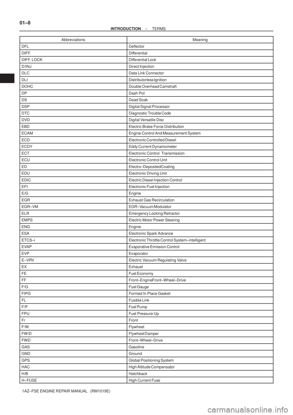
01±8
± INTRODUCTIONTERMS
1AZ±FSE ENGINE REPAIR MANUAL (RM1019E)Abbreviations Meaning
DFLDeflector
DIFF.Differential
DIFF. LOCKDifferential Lock
D/INJDirect Injection
DLCData Link Connector
DLIDistributorless Ignition
DOHCDouble Overhead Camshaft
DPDash Pot
DSDead Soak
DSPDigital Signal Processor
DTCDiagnostic Trouble Code
DVDDigital Versatile Disc
EBDElectric Brake Force Distribution
ECAMEngine Control And Measurement System
ECDElectronic Controlled Diesel
ECDYEddy Current Dynamometer
ECTElectronic Control Transmission
ECUElectronic Control Unit
EDElectro±Deposited Coating
EDUElectronic Driving Unit
EDICElectric Diesel Injection Control
EFIElectronic Fuel Injection
E/GEngine
EGRExhaust Gas Recirculation
EGR±VMEGR±Vacuum Modulator
ELREmergency Locking Retractor
EMPSElectric Motor Power Steering
ENGEngine
ESAElectronic Spark Advance
ETCS±iElectronic Throttle Control System±intelligent
EVAPEvaporative Emission Control
EVPEvaporator
E±VRVElectric Vacuum Regulating Valve
EXExhaust
FEFuel Economy
FFFront±Engine Front±Wheel±Drive
F/GFuel Gauge
FIPGFormed In Place Gasket
FLFusible Link
F/PFuel Pump
FPUFuel Pressure Up
FrFront
F/WFlywheel
FW/DFlywheel Damper
FWDFront±Wheel±Drive
GASGasoline
GNDGround
GPSGlobal Positioning System
HACHigh Altitude Compensator
H/BHatchback
H±FUSEHigh Current Fuse