Page 2647 of 5135
C82031
N
������G25654
Groove
Neutral
Basic Line
C62669
C82032
C81535
40±6
± AUTOMATIC TRANSMISSION / TRANSPARK/NEUTRAL POSITION SWITCH ASSY (ATM)
AVENSIS REPAIR MANUAL (RM1018E)
(5) Turn the lever counterclockwise until it stops, then
turn it clockwise 2 notches.
(6) Remove the control shaft lever.
(7) Align the groove with the Gneutral basic line.
(8) Hold the switch in position and tighten the 2 bolts.
Torque: 5.4 N�m (55 kgf�cm, 48 in. lbf)
(9) Using a screwdriver, stake the nut with the lock
plate.
(10) Install the control shaft lever, washer and nut.
Torque: 13 N�m (130 kgf�cm, 9 ft�lbf)
(11) Connect the park/neutral position switch connector.
5. INSTALL TRANSMISSION CONTROL CABLE ASSY
(a) Install the control cable and clip to the control cable brack-
et.
Page 2670 of 5135
320G5±02
F45426
F45427
F42642
±
BRAKE STEERING SENSOR
32±65
AVENSIS REPAIR MANUAL (RM1018E)
STEERING SENSOR
REPLACEMENT
1.PRECAUTION (See page 60±1)
2. REMOVE PLACE FRONT WHEELS FACING STRAIGHT AHEAD
3.DISCONNECT BATTERY NEGATIVE TERMINAL (See page 60±1)
4.REMOVE HORN BUTTON ASSY (See page 60±17)
5.REMOVE STEERING WHEEL ASSY (See page 50±9)
6.REMOVE STEERING COLUMN COVER LWR (See page 50±9)
7. REMOVE STEERING COLUMN COVER W/INSTRUMENT CLUSTER FINISH PANEL ASSY
(See page 50±9)
8.REMOVE STEERING COLUMN ASSY(See page 50±9)
9.REMOVE STEERING INTERMEDIATE SHAFT ASSY NO.2 (See page 50±9)
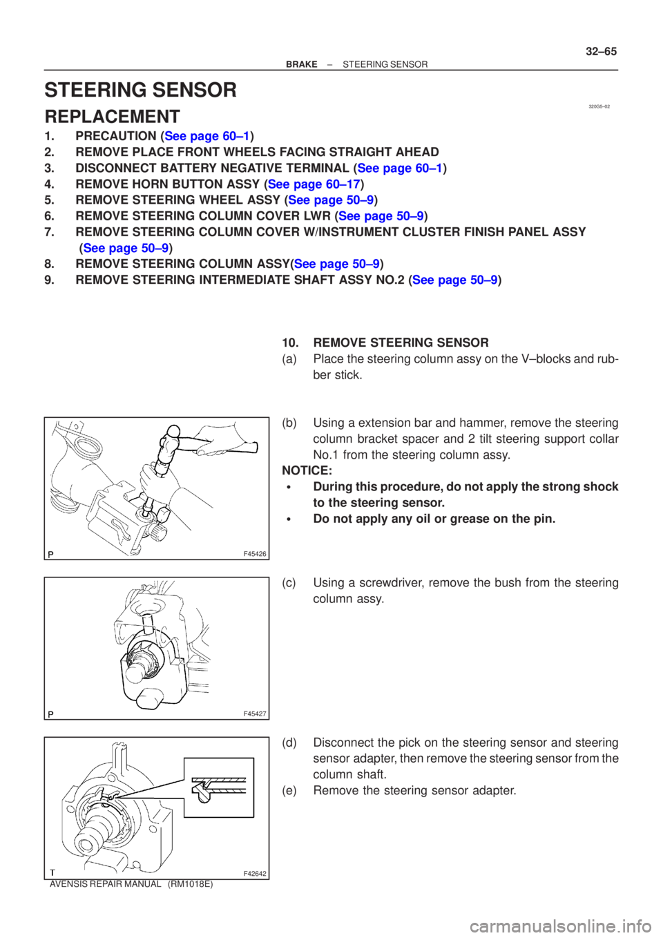
10. REMOVE STEERING SENSOR
(a) Place the steering column assy on the V±blocks and rub-ber stick.
(b) Using a extension bar and hammer, remove the steering column bracket spacer and 2 tilt steering support collar
No.1 from the steering column assy.
NOTICE:
�During this procedure, do not apply the strong shock
to the steering sensor.
�Do not apply any oil or grease on the pin.
(c) Using a screwdriver, remove the bush from the steering column assy.
(d) Disconnect the pick on the steering sensor and steering sensor adapter, then remove the steering sensor from the
column shaft.
(e) Remove the steering sensor adapter.
Page 2695 of 5135
D30345
D25745
No. 1 Engine HangerNo. 2 Engine Hanger
C80168
±
AUTOMATIC TRANSMISSION / TRANS AUTOMATIC TRANSAXLE ASSY (U241E)
40±27
AVENSIS REPAIR MANUAL (RM1018E)
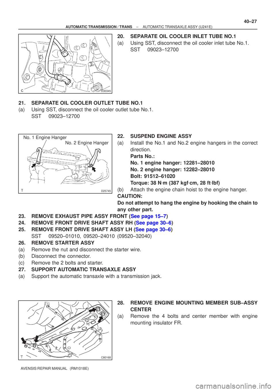
20. SEPARATE OIL COOLER INLET TUBE NO.1
(a) Using SST, disconnect the oil cooler inlet tube No.1.
SST 09023±12700
21. SEPARATE OIL COOLER OUTLET TUBE NO.1
(a) Using SST, disconnect the oil cooler outlet tube No.1. SST 09023±12700
22. SUSPEND ENGINE ASSY
(a) Install the No.1 and No.2 engine hangers in the correctdirection.
Parts No.:
No. 1 engine hanger: 12281±28010
No. 2 engine hanger: 12282±28010
Bolt: 91512±61020
Torque: 38 N �m (387 kgf �cm, 28 ft �lbf)
(b) Attach the engine chain hoist to the engine hanger.
CAUTION:
Do not attempt to hang the engine by hooking the chain to
any other part.
23.REMOVE EXHAUST PIPE ASSY FRONT (See page 15±7)
24.REMOVE FRONT DRIVE SHAFT ASSY RH (See page 30±6)
25.REMOVE FRONT DRIVE SHAFT ASSY LH (See page 30±6) SST 09520±01010, 09520±24010 (09520±32040)
26. REMOVE STARTER ASSY
(a) Remove the nut and disconnect the starter wire.
(b) Disconnect the connector.
(c) Remove the 2 bolts and starter.
27. SUPPORT AUTOMATIC TRANSAXLE ASSY
(a) Support the automatic transaxle with a transmission jack.
28. REMOVE ENGINE MOUNTING MEMBER SUB±ASSYCENTER
(a) Remove the 4 bolts and center member with engine
mounting insulator FR.
Page 2698 of 5135
�C83051
D25371
Key
C57914
C88330
40±30
±
AUTOMATIC TRANSMISSION / TRANS AUTOMATIC TRANSAXLE ASSY (U241E)
AVENSIS REPAIR MANUAL (RM1018E)
37. REMOVE TORQUE CONVERTER CLUTCH ASSY
38.INSPECT TORQUE CONVERTER CLUTCH ASSY (See page 40±37) SST 09350±32014 (09351±32010, 09351±32020)
39. INSTALL TORQUE CONVERTER CLUTCH ASSY
(a) Using vernier calipers, measure the dimension A be-tween the transaxle and the end surface of the drive plate.
(b) Set the key of the front oil pump drive gear at the top and put a mark on the housing.
(c) Put a mark on the torque converter clutch so that its groove can be clearly indicated.
(d) Match the 2 marks on the transaxle case and the torque converter clutch and fit the splined part of the input shaft
to the spline part of the turbine runner.
Page 2699 of 5135
C88300
C88301
C88654Dimension B
�
�
�
�
�
�
���C89268
D25408
± AUTOMATIC TRANSMISSION / TRANSAUTOMATIC TRANSAXLE ASSY (U241E)
40±31
AVENSIS REPAIR MANUAL (RM1018E)
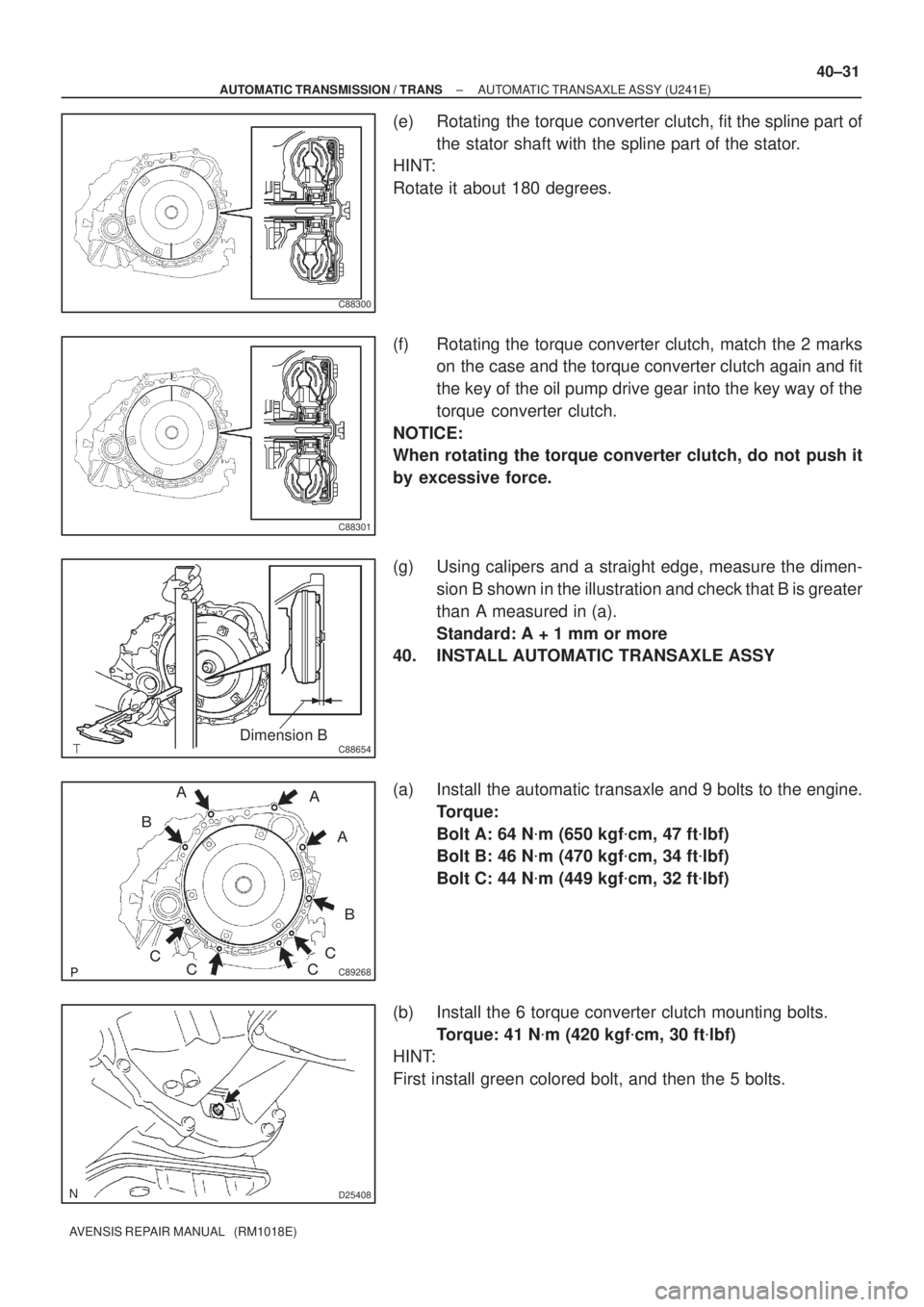
(e) Rotating the torque converter clutch, fit the spline part of
the stator shaft with the spline part of the stator.
HINT:
Rotate it about 180 degrees.
(f) Rotating the torque converter clutch, match the 2 marks
on the case and the torque converter clutch again and fit
the key of the oil pump drive gear into the key way of the
torque converter clutch.
NOTICE:
When rotating the torque converter clutch, do not push it
by excessive force.
(g) Using calipers and a straight edge, measure the dimen-
sion B shown in the illustration and check that B is greater
than A measured in (a).
Standard: A + 1 mm or more
40. INSTALL AUTOMATIC TRANSAXLE ASSY
(a) Install the automatic transaxle and 9 bolts to the engine.
Torque:
Bolt A: 64 N�m (650 kgf�cm, 47 ft�lbf)
Bolt B: 46 N�m (470 kgf�cm, 34 ft�lbf)
Bolt C: 44 N�m (449 kgf�cm, 32 ft�lbf)
(b) Install the 6 torque converter clutch mounting bolts.
Torque: 41 N�m (420 kgf�cm, 30 ft�lbf)
HINT:
First install green colored bolt, and then the 5 bolts.
Page 2701 of 5135
D30351
D30861
B
A
A
AA
C85797
C80168
A
A
BC
±
AUTOMATIC TRANSMISSION / TRANS AUTOMATIC TRANSAXLE ASSY (U241E)
40±33
AVENSIS REPAIR MANUAL (RM1018E)
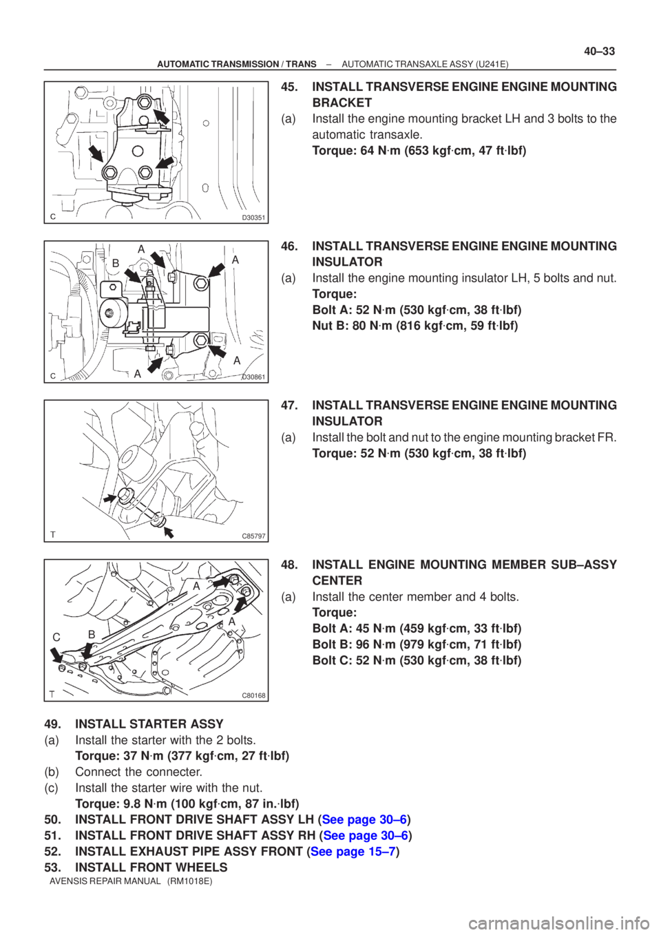
45. INSTALL TRANSVERSE ENGINE ENGINE MOUNTING
BRACKET
(a) Install the engine mounting bracket LH and 3 bolts to the
automatic transaxle.
Torque: 64 N �m (653 kgf �cm, 47 ft �lbf)
46. INSTALL TRANSVERSE ENGINE ENGINE MOUNTING INSULATOR
(a) Install the engine mounting insulator LH, 5 bolts and nut. Torque:
Bolt A: 52 N �m (530 kgf �cm, 38 ft �lbf)
Nut B: 80 N �m (816 kgf �cm, 59 ft �lbf)
47. INSTALL TRANSVERSE ENGINE ENGINE MOUNTING INSULATOR
(a) Install the bolt and nut to the engine mounting bracket FR. Torque: 52 N �m (530 kgf �cm, 38 ft �lbf)
48. INSTALL ENGINE MOUNTING MEMBER SUB±ASSY CENTER
(a) Install the center member and 4 bolts. Torque:
Bolt A: 45 N �m (459 kgf �cm, 33 ft �lbf)
Bolt B: 96 N �m (979 kgf �cm, 71 ft �lbf)
Bolt C: 52 N �m (530 kgf �cm, 38 ft �lbf)
49. INSTALL STARTER ASSY
(a) Install the starter with the 2 bolts. Torque: 37 N �m (377 kgf �cm, 27 ft �lbf)
(b) Connect the connecter.
(c) Install the starter wire with the nut. Torque: 9.8 N �m (100 kgf �cm, 87 in. �lbf)
50.INSTALL FRONT DRIVE SHAFT ASSY LH (See page 30±6)
51.INSTALL FRONT DRIVE SHAFT ASSY RH (See page 30±6)
52.INSTALL EXHAUST PIPE ASSY FRONT (See page 15±7)
53. INSTALL FRONT WHEELS
Page 2706 of 5135
D30356
x6
�Gasket
�Non±reusable Part: Specified torque
Torque Converter Clutch Assy
41 (420, 30)
Flywheel Housing
Under Cover
44 (449, 32)
46 (470, 34)
44 (449, 32)
Engine Under Cover RH
Engine Under Cover LH
Engine Mounting
Bracket FR
52 (530, 38)
64 (653, 47)
64 (653, 17)
45 (459, 33)
Engine Mounting Member Sub±Assy Center
96 (979, 71)
52 (530, 38)
52 (530, 38)64 (653, 47)
87 (887, 64)
Engine Mounting
Bracket RR
64 (653, 47)
Engine
Mounting
Insulator RR
Front Drive
Shaft Assy LH
Automatic Transaxle Assy
�Snap Ring
Gasket
Exhaust Pipe
Assy Front
52 (530, 38)64 (650, 47)
80 (815, 59)
Engine
Mounting
Insulator LH
52 (530, 38)64 (653, 47)
Engine Mounting
Bracket LH
Drain Plug
N�m (kgf�cm, ft�lbf)
46 (470, 34)
49 (500, 36)
�
Front Drive Shaft Assy RH
64 (650, 47)
64 (650, 47)
64 (650, 47)
40±24
± AUTOMATIC TRANSMISSION / TRANSAUTOMATIC TRANSAXLE ASSY (U241E)
AVENSIS REPAIR MANUAL (RM1018E)
Page 2709 of 5135
C91882
C94723
D25372
±
AUTOMATIC TRANSMISSION / TRANS AUTOMATIC TRANSAXLE ASSY (U341E)
40±13
AVENSIS REPAIR MANUAL (RM1018E)
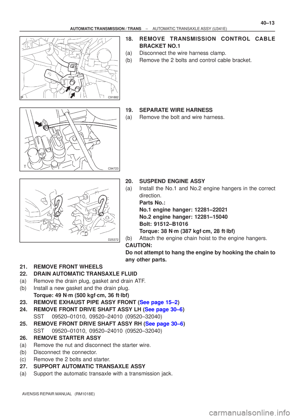
18. REMOVE TRANSMISSION CONTROL CABLE
BRACKET NO.1
(a) Disconnect the wire harness clamp.
(b) Remove the 2 bolts and control cable bracket.
19. SEPARATE WIRE HARNESS
(a) Remove the bolt and wire harness.
20. SUSPEND ENGINE ASSY
(a) Install the No.1 and No.2 engine hangers in the correct
direction.
Parts No.:
No.1 engine hanger: 12281±22021
No.2 engine hanger: 12281±15040
Bolt: 91512±B1016
Torque: 38 N �m (387 kgf �cm, 28 ft �lbf)
(b) Attach the engine chain hoist to the engine hangers.
CAUTION:
Do not attempt to hang the engine by hooking the chain to
any other parts.
21. REMOVE FRONT WHEELS
22. DRAIN AUTOMATIC TRANSAXLE FLUID
(a) Remove the drain plug, gasket and drain ATF.
(b) Install a new gasket and the drain plug. Torque: 49 N �m (500 kgf �cm, 36 ft �lbf)
23.REMOVE EXHAUST PIPE ASSY FRONT (See page 15±2)
24.REMOVE FRONT DRIVE SHAFT ASSY LH (See page 30±6)
SST 09520±01010, 09520±24010 (09520±32040)
25.REMOVE FRONT DRIVE SHAFT ASSY RH (See page 30±6) SST 09520±01010, 09520±24010 (09520±32040)
26. REMOVE STARTER ASSY
(a) Remove the nut and disconnect the starter wire.
(b) Disconnect the connector.
(c) Remove the 2 bolts and starter.
27. SUPPORT AUTOMATIC TRANSAXLE ASSY
(a) Support the automatic transaxle with a transmission jack.