Page 2788 of 5135
D30473
Front Drive Shaft Assy RH
� Snap Ring
Transverse Engine
Engine Mounting Insulator
64 (653, 47)
87 (887, 64)
� Cotter Pin
64 (653, 47)
� Cotter Pin
Engine Under Cover RH
� Non±reusable part
N´m (kgf´cm, ft´lbf)
: Specified torque
64 (653, 47)
�216 (2,203, 159)45 (459, 33)
Engine Under Cover LH
35 (360, 26)
74 (755, 55)
52 (530, 38)
49 (500, 36)
133 (1,356, 83)
49 (500, 36)
89 (908, 66)
Transverse Engine
Engine Mounting Bracket
133 (1,356, 83)
52 (530, 38)89 (908, 66)
29 (296, 21)Transverse Engine
Engine Mounting Insulator
Transverse Engine
Engine Mounting Bracket
8.0 (82, 71 in.�lbf)
74 (755, 55)
Front Drive Shaft Assy LH
64 (650, 47)
64 (650, 47)
± MANUAL TRANSMISSION/TRANSAXLEMANUAL TRANSAXLE ASSY (1AZ±FE/1AZ±FSE)
41±23
AVENSIS REPAIR MANUAL (RM1018E)
Page 2790 of 5135
D30481
D30061
G24210
D11561
41±16
±
MANUAL TRANSMISSION/TRANSAXLE MANUAL TRANSAXLE ASSY (1ZZ±FE/3ZZ±FE)
AVENSIS REPAIR MANUAL (RM1018E)
20. DISCONNECT CONNECTOR
(a) Disconnect the back±up lamp switch connector.
21. SEPARATE CLUTCH RELEASE CYLINDER ASSY
(a) Remove the 5 bolts, separate the release cylinder assy with clutch piping from the transaxle.
22. SEPARATE CHARCOAL CANISTER ASSY 23. SEPARATE TRANSMISSION CONTROL CABLE ASSY
(a) Remove the 2 clips, disconnect the 2 cables from thetransaxle.
(b) Remove the 2 clips, disconnect the 2 cables from the con-
trol cable bracket.
24. REMOVE STARTER ASSY
(a) Remove the nut and disconnect the starter wire.
(b) Disconnect the connector.
(c) Remove the 2 bolts and starter assy.
25.REMOVE FRONT DRIVE SHAFT ASSY LH(See page 30±6) SST 09520±01010, 09520±24010 (09520±32040)
26.REMOVE FRONT DRIVE SHAFT ASSY RH (See page 30±6) SST 09520±01010, 09520±24010 (09520±32040)
Page 2793 of 5135

D30484
D30483
A
A
A
A
B
D11561
(a)
(c)
(b)(a)
G24210
±
MANUAL TRANSMISSION/TRANSAXLE MANUAL TRANSAXLE ASSY (1ZZ±FE/3ZZ±FE)
41±19
AVENSIS REPAIR MANUAL (RM1018E)
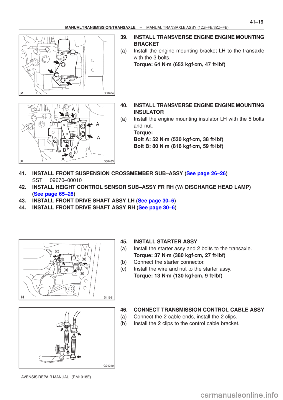
39. INSTALL TRANSVERSE ENGINE ENGINE MOUNTING
BRACKET
(a) Install the engine mounting bracket LH to the transaxle
with the 3 bolts.
Torque: 64 N �m (653 kgf �cm, 47 ft �lbf)
40. INSTALL TRANSVERSE ENGINE ENGINE MOUNTING INSULATOR
(a) Install the engine mounting insulator LH with the 5 bolts and nut.
Torque:
Bolt A: 52 N �m (530 kgf �cm, 38 ft �lbf)
Bolt B: 80 N �m (816 kgf �cm, 59 ft �lbf)
41.INSTALL FRONT SUSPENSION CROSSMEMBER SUB±ASSY (See page 26±26) SST 09670±00010
42. INSTALL HEIGHT CONTROL SENSOR SUB±ASSY FR RH (W/ DISCHARGE HEAD LAMP) (See page 65±28)
43.INSTALL FRONT DRIVE SHAFT ASSY LH (See page 30±6)
44.INSTALL FRONT DRIVE SHAFT ASSY RH (See page 30±6)
45. INSTALL STARTER ASSY
(a) Install the starter assy and 2 bolts to the transaxle.Torque: 37 N �m (380 kgf �cm, 27 ft �lbf)
(b) Connect the starter connector.
(c) Install the wire and nut to the starter assy.
Torque: 13 N �m (130 kgf �cm, 9 ft �lbf)
46. CONNECT TRANSMISSION CONTROL CABLE ASSY
(a) Connect the 2 cable ends, install the 2 clips.
(b) Install the 2 clips to the control cable bracket.
Page 2797 of 5135
D30479
Front Drive Shaft Assy RH� Snap Ring
Front Drive
� Snap Ring
Transverse Engine
Engine Mounting BracketTransverse Engine
Engine Mounting Insulator
64 (653, 47)
87 (887, 64)Transverse Engine
Engine Mounting Bracket
� Cotter Pin
64 (653, 47)
52 (530, 38)
� Cotter Pin
Engine Under Cover RH
� Non±reusable part
N´m (kgf´cm, ft´lbf)
: Specified torque
64 (653, 47)
�216 (2,203, 159)45 (459, 33)
Engine Under Cover LH
35 (360, 26)
74 (755, 55)
52 (530, 38)
49 (500, 36)
133 (1,356, 83)
29 (296, 21)
49 (500, 36)
74 (755, 55)
89 (908, 66)
8.0 (82, 71 in.�lbf)
133 (1,356, 83)
89 (908, 66)
41±14
± MANUAL TRANSMISSION/TRANSAXLEMANUAL TRANSAXLE ASSY (1ZZ±FE/3ZZ±FE)
AVENSIS REPAIR MANUAL (RM1018E)
Page 2798 of 5135

5100G±06
51±2
±
POWER STEERING POWER STEERING SYSTEM
AVENSIS REPAIR MANUAL (RM1018E)
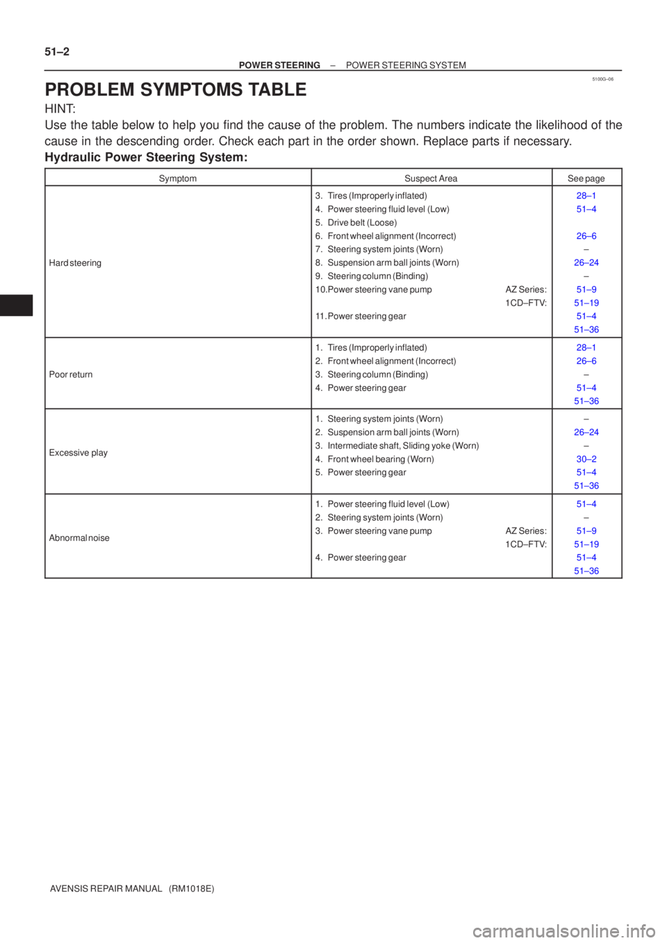
PROBLEM SYMPTOMS TABLE
HINT:
Use the table below to help you find the cause of the problem. The numbers \
indicate the likelihood of the
cause in the descending order. Check each part in the order shown. Replace parts if necessary.
Hydraulic Power Steering System:
SymptomSuspect AreaSee page
Hard steering
3. Tires (Improperly inflated)
4. Power steering fluid level (Low)
5. Drive belt (Loose)
6. Front wheel alignment (Incorrect)
7. Steering system joints (Worn)
8. Suspension arm ball joints (Worn)
9. Steering column (Binding)
10.Power steering vane pump AZ Series: 1CD±FTV:
11. Power steering gear28±1
51±4
26±6 ±
26±24 ±
51±9
51±19 51±4
51±36
Poor return
1. Tires (Improperly inflated)
2. Front wheel alignment (Incorrect)
3. Steering column (Binding)
4. Power steering gear28±1
26±6 ±
51±4
51±36
Excessive play
1. Steering system joints (Worn)
2. Suspension arm ball joints (Worn)
3. Intermediate shaft, Sliding yoke (Worn)
4. Front wheel bearing (Worn)
5. Power steering gear±
26±24 ±
30±2
51±4
51±36
Abnormal noise
1. Power steering fluid level (Low)
2. Steering system joints (Worn)
3. Power steering vane pump AZ Series: 1CD±FTV:
4. Power steering gear51±4
±
51±9
51±19 51±4
51±36
Page 2809 of 5135

F44793Matchmarks
F44794
Screw
Extractor
F44795
SST
F44796
F44797
50±14
±
STEERING COLUMN STEERING COLUMN ASSY
AVENSIS REPAIR MANUAL (RM1018E)
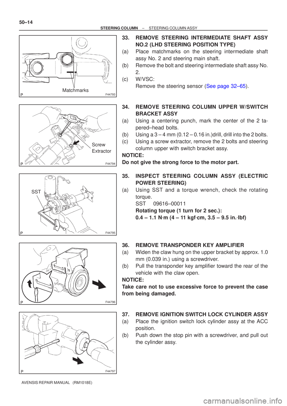
33. REMOVE STEERING INTERMEDIATE SHAFT ASSY NO.2 (LHD STEERING POSITION TYPE)
(a) Place matchmarks on the steering intermediate shaft
assy No. 2 and steering main shaft.
(b) Remove the bolt and steering intermediate shaft assy No. 2.
(c) W/VSC:
Remove the steering sensor (See page 32±65).
34. REMOVE STEERING COLUMN UPPER W/SWITCH BRACKET ASSY
(a) Using a centering punch, mark the center of the 2 ta- pered±head bolts.
(b) Using a 3 ± 4 mm (0.12 ± 0.16 in.)drill, drill into the 2 bolts.
(c) Using a screw extractor, remove the 2 bolts and steering column upper with switch bracket assy.
NOTICE:
Do not give the strong force to the motor part.
35. INSPECT STEERING COLUMN ASSY (ELECTRIC POWER STEERING)
(a) Using SST and a torque wrench, check the rotating torque.
SST 09616±00011
Rotating torque (1 turn for 2 sec.):
0.4 ± 1.1 N �m (4 ± 11 kgf �cm, 3.5 ± 9.5 in. �lbf)
36. REMOVE TRANSPONDER KEY AMPLIFIER
(a) Widen the claw hung on the upper bracket by approx. 1.0 mm (0.039 in.) using a screwdriver.
(b) Pull the transponder key amplifier toward the rear of the
vehicle with the claw open.
NOTICE:
Take care not to use excessive force to prevent the case
from being damaged.
37. REMOVE IGNITION SWITCH LOCK CYLINDER ASSY
(a) Place the ignition switch lock cylinder assy at the ACC position.
(b) Push down the stop pin with a screwdriver, and pull out the cylinder assy.
Page 2820 of 5135

5000D±14
50±2
±
STEERING COLUMN STEERING SYSTEM
AVENSIS REPAIR MANUAL (RM1018E)
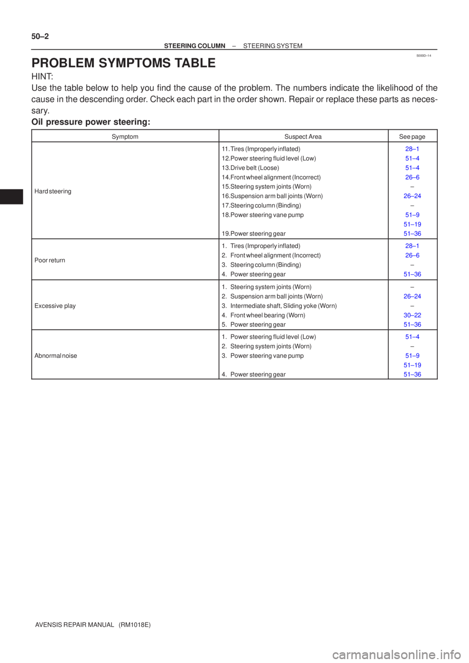
PROBLEM SYMPTOMS TABLE
HINT:
Use the table below to help you find the cause of the problem. The numbers \
indicate the likelihood of the
cause in the descending order. Check each part in the order shown. Repair or replace these parts as n\
eces-
sary.
Oil pressure power steering:
SymptomSuspect AreaSee page
Hard steering
11. Tires (Improperly inflated)
12.Power steering fluid level (Low)
13.Drive belt (Loose)
14.Front wheel alignment (Incorrect)
15.Steering system joints (Worn)
16.Suspension arm ball joints (Worn)
17.Steering column (Binding)
18.Power steering vane pump
19.Power steering gear28±1
51±4
51±4
26±6 ±
26±24 ±
51±9
51±19
51±36
Poor return
1. Tires (Improperly inflated)
2. Front wheel alignment (Incorrect)
3. Steering column (Binding)
4. Power steering gear28±1
26±6 ±
51±36
Excessive play
1. Steering system joints (Worn)
2. Suspension arm ball joints (Worn)
3. Intermediate shaft, Sliding yoke (Worn)
4. Front wheel bearing (Worn)
5. Power steering gear±
26±24 ±
30±22
51±36
Abnormal noise
1. Power steering fluid level (Low)
2. Steering system joints (Worn)
3. Power steering vane pump
4. Power steering gear51±4 ±
51±9
51±19
51±36
Page 2862 of 5135
������D30361
C84483
C57767
C65368
51±20
± POWER STEERINGVANE PUMP ASSY (1CD±FTV)
AVENSIS REPAIR MANUAL (RM1018E)
8. REMOVE FLOW CONTROL VALVE ASSY
(a) Remove the pressure port union sub±assy.
(b) Remove the O±ring from the pressure port union sub±
assy.
(c) Remove the flow control valve assy and the compression
spring.
9. REMOVE VANE PUMP HOUSING SUB±ASSY REAR
(a) Remove the 4 bolts and housing sub±assy rear from the
housing sub±assy front.
(b) Remove the O±ring from the housing sub±assy rear.
10. REMOVE W/PULLEY SHAFT SUB±ASSY
(a) Using 2 screwdrivers, remove the snap ring from the w/
pulley shaft sub±assy.
(b) Remove the w/pulley shaft sub±assy.
11. REMOVE VANE PUMP ROTOR
(a) Remove the 10 vane pump plates.
(b) Remove the vane pump rotor.
12. REMOVE VANE PUMP CAM RING
13. REMOVE VANE PUMP SIDE PLATE FRONT
(a) Remove the side plate front from the housing sub±assy
front.
(b) Remove the O±ring from the side plate front.