Page 2599 of 5135
300JZ±01
������F45267
F44818
������F45752
SST
±
DRIVE SHAFT / PROPELLER SHAFT REAR AXLE CARRIER SUB±ASSY LH
30±31
AVENSIS REPAIR MANUAL (RM1018E)
REPLACEMENT
HINT:
Replace the RH side by the same procedures as the LH side.
1. INSPECT REAR AXLE CARRIER SUB±ASSY LH
(a) Check that there is no looseness on the ball joint by shaking the lower arm up and down with a force
of 294 N (30kgf, 66 lbf).
2. REMOVE REAR WHEEL
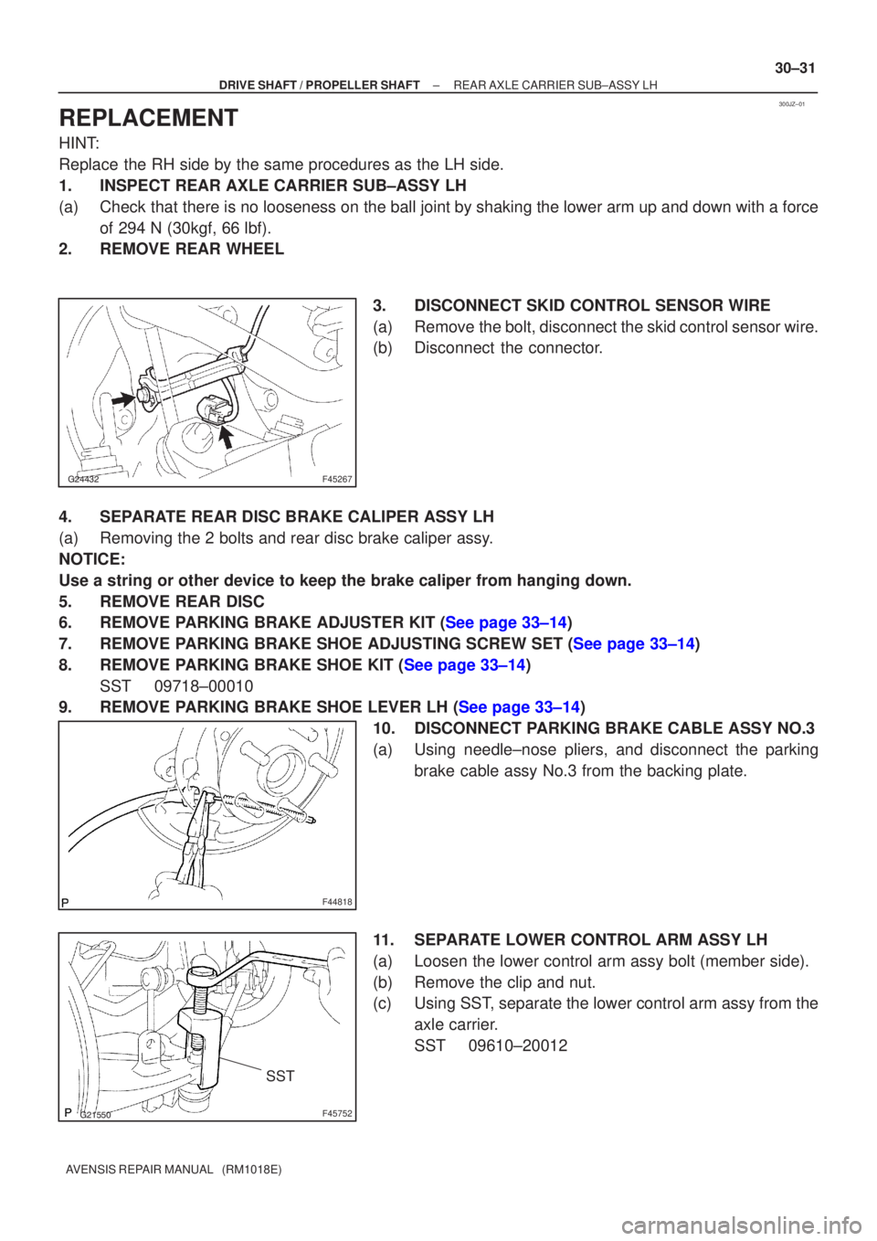
3. DISCONNECT SKID CONTROL SENSOR WIRE
(a) Remove the bolt, disconnect the skid control sensor wire.
(b) Disconnect the connector.
4. SEPARATE REAR DISC BRAKE CALIPER ASSY LH
(a) Removing the 2 bolts and rear disc brake caliper assy.
NOTICE:
Use a string or other device to keep the brake caliper from hanging down\
.
5. REMOVE REAR DISC
6.REMOVE PARKING BRAKE ADJUSTER KIT (See page 33±14)
7.REMOVE PARKING BRAKE SHOE ADJUSTING SCREW SET (See page 33±14)
8.REMOVE PARKING BRAKE SHOE KIT (See page 33±14) SST 09718±00010
9.REMOVE PARKING BRAKE SHOE LEVER LH (See page 33±14)
10. DISCONNECT PARKING BRAKE CABLE ASSY NO.3
(a) Using needle±nose pliers, and disconnect the parkingbrake cable assy No.3 from the backing plate.
11. SEPARATE LOWER CONTROL ARM ASSY LH
(a) Loosen the lower control arm assy bolt (member side).
(b) Remove the clip and nut.
(c) Using SST, separate the lower control arm assy from the axle carrier.
SST 09610±20012
Page 2600 of 5135
������F45753HoldTurn
SST
G21537
G21542
G20965
30±32
± DRIVE SHAFT / PROPELLER SHAFTREAR AXLE CARRIER SUB±ASSY LH
AVENSIS REPAIR MANUAL (RM1018E)
12. SEPARATE REAR SUSPENSION ARM ASSY NO.1 LH
(a) Remove the clip and nut.
(b) Using SST, separate the rear suspension arm assy No.1
(ball joint side).
SST 09628±62011
(c) Remove the bolt and nut, separate the rear suspension
arm assy No.1.
NOTICE:
When removing the bolt, hold the nut not to rotate.
13. SEPARATE UPPER CONTROL ARM ASSY
(a) Remove the bolt and nut, separate the upper control arm
assy from the axle carrier.
NOTICE:
When removing the bolt, hold the nut not to rotate.
14. REMOVE REAR AXLE CARRIER SUB±ASSY LH
(a) Remove the 4 bolts and nut, hub & bearing assy and axle
carrier sub±assy.
Page 2601 of 5135
G21613
G20965
G21542
G21537
± DRIVE SHAFT / PROPELLER SHAFTREAR AXLE CARRIER SUB±ASSY LH
30±33
AVENSIS REPAIR MANUAL (RM1018E)
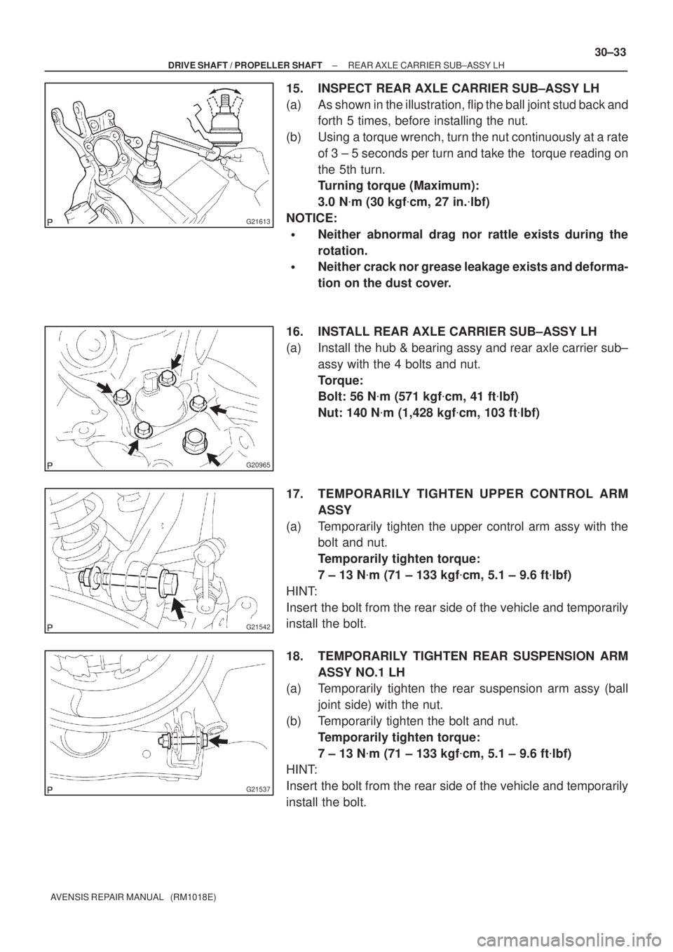
15. INSPECT REAR AXLE CARRIER SUB±ASSY LH
(a) As shown in the illustration, flip the ball joint stud back and
forth 5 times, before installing the nut.
(b) Using a torque wrench, turn the nut continuously at a rate
of 3 ± 5 seconds per turn and take the torque reading on
the 5th turn.
Turning torque (Maximum):
3.0 N�m (30 kgf�cm, 27 in.�lbf)
NOTICE:
�Neither abnormal drag nor rattle exists during the
rotation.
�Neither crack nor grease leakage exists and deforma-
tion on the dust cover.
16. INSTALL REAR AXLE CARRIER SUB±ASSY LH
(a) Install the hub & bearing assy and rear axle carrier sub±
assy with the 4 bolts and nut.
Torque:
Bolt: 56 N�m (571 kgf�cm, 41 ft�lbf)
Nut: 140 N�m (1,428 kgf�cm, 103 ft�lbf)
17. TEMPORARILY TIGHTEN UPPER CONTROL ARM
ASSY
(a) Temporarily tighten the upper control arm assy with the
bolt and nut.
Temporarily tighten torque:
7 ± 13 N�m (71 ± 133 kgf�cm, 5.1 ± 9.6 ft�lbf)
HINT:
Insert the bolt from the rear side of the vehicle and temporarily
install the bolt.
18. TEMPORARILY TIGHTEN REAR SUSPENSION ARM
ASSY NO.1 LH
(a) Temporarily tighten the rear suspension arm assy (ball
joint side) with the nut.
(b) Temporarily tighten the bolt and nut.
Temporarily tighten torque:
7 ± 13 N�m (71 ± 133 kgf�cm, 5.1 ± 9.6 ft�lbf)
HINT:
Insert the bolt from the rear side of the vehicle and temporarily
install the bolt.
Page 2602 of 5135
G21543
F44820
������F45267
30±34
±
DRIVE SHAFT / PROPELLER SHAFT REAR AXLE CARRIER SUB±ASSY LH
AVENSIS REPAIR MANUAL (RM1018E)
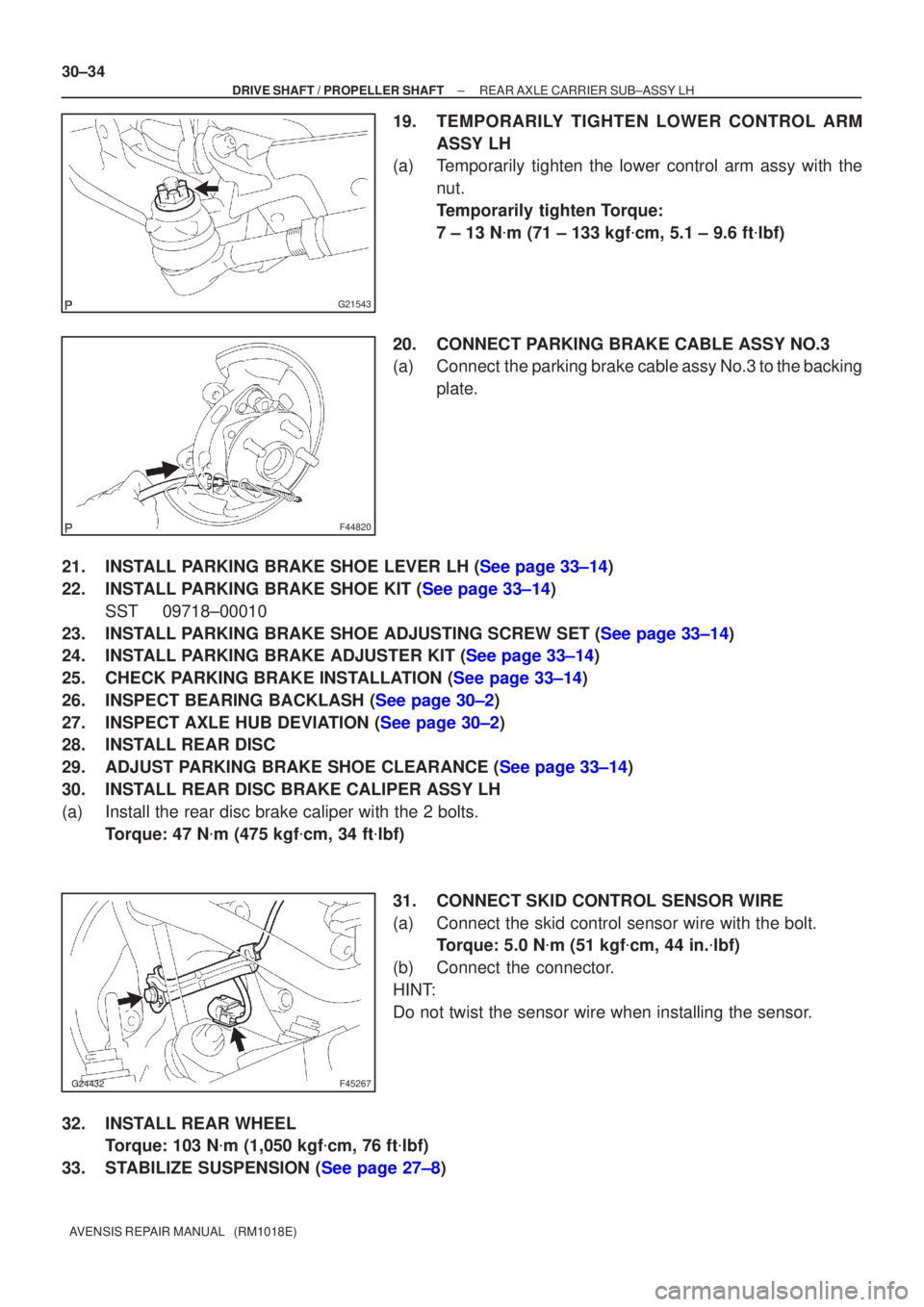
19.TEMPORARILY TIGHTEN LOWER CONTROL ARM ASSY LH
(a)Temporarily tighten the lower control arm assy with the
nut.
Temporarily tighten Torque:
7 ± 13 N �m (71 ± 133 kgf �cm, 5.1 ± 9.6 ft �lbf)
20.CONNECT PARKING BRAKE CABLE ASSY NO.3
(a)Connect the parking brake cable assy No.3 to the backing plate.
21.INSTALL PARKING BRAKE SHOE LEVER LH (See page 33±14)
22.INSTALL PARKING BRAKE SHOE KIT (See page 33±14) SST 09718±00010
23.INSTALL PARKING BRAKE SHOE ADJUSTING SCREW SET (See page 33±14)
24.INSTALL PARKING BRAKE ADJUSTER KIT (See page 33±14)
25.CHECK PARKING BRAKE INSTALLATION (See page 33±14)
26.INSPECT BEARING BACKLASH (See page 30±2)
27.INSPECT AXLE HUB DEVIATION (See page 30±2)
28. INSTALL REAR DISC
29.ADJUST PARKING BRAKE SHOE CLEARANCE (See page 33±14)
30. INSTALL REAR DISC BRAKE CALIPER ASSY LH
(a) Install the rear disc brake caliper with the 2 bolts. Torque: 47 N �m (475 kgf �cm, 34 ft �lbf)
31. CONNECT SKID CONTROL SENSOR WIRE
(a) Connect the skid control sensor wire with the bolt. Torque: 5.0 N �m (51 kgf �cm, 44 in. �lbf)
(b) Connect the connector.
HINT:
Do not twist the sensor wire when installing the sensor.
32. INSTALL REAR WHEEL Torque: 103 N �m (1,050 kgf �cm, 76 ft �lbf)
33.STABILIZE SUSPENSION (See page 27±8)
Page 2603 of 5135
±
DRIVE SHAFT / PROPELLER SHAFT REAR AXLE CARRIER SUB±ASSY LH
30±35
AVENSIS REPAIR MANUAL (RM1018E)
34. FULLY TIGHTEN UPPER CONTROL ARM ASSY
(a) Fully tighten the bolt.
Torque: 74 N �m (755 kgf �cm, 55 ft �lbf)
NOTICE:
When installing the bolt, hold the nut not to rotate.
35. FULLY TIGHTEN REAR SUSPENSION ARM ASSY NO.1 LH
(a) Fully tighten the nut (ball joint side). Torque: 105 N �m (1,071 kgf �cm, 77 ft �lbf)
(b) Install the clip.
NOTICE:
If the holes for the clip are not aligned, tighten the nut up to 60 � further.
(c) Fully tighten the bolt and nut.
Torque: 74 N �m (755 kgf �cm, 55 ft �lbf)
NOTICE:
When installing the bolt, hold the nut not to rotate.
36. FULLY TIGHTEN LOWER CONTROL ARM ASSY LH
(a) Fully tighten the nut. Torque: 60 N �m (612 kgf �cm, 44 ft �lbf)
(b) Install the clip.
NOTICE:
If the holes for the clip are not aligned, tighten the nut up to 60 � further.
(c) Fully tighten the bolt (member side). Torque: 105 N �m (1,071 kgf �cm, 77 ft �lbf)
NOTICE:
When installing the bolt, hold the nut not to rotate.
37.INSPECT AND ADJUST PARKING BRAKE LEVER TRAVEL (See page 33±2)
38.INSPECT AND ADJUST REAR WHEEL ALIGNMENT (See page 27±4)
39. CHECK ABS SPEED SENSOR SIGNAL
(a)ABD WITH EBD SYSTEM (See page 05±699)
(b)ABD WITH EBD & BA & TRC & VSC SYSTEM ( See page 05±756)
Page 2604 of 5135
30093±02
������F45576
Skid Control Sensor Wire
5.0 (51, 44 in.�lbf)
Upper Control Arm Assy LH
�Clip
74 (755, 55)
60 (612, 44)Lower Control Arm Assy LH
Parking Brake Shoe
Rear Disc
47 (475, 34)
Rear Disc Brake Caliper Assy LH
�Clip
105 (1,071, 77)
Parking Brake Shoe
140 (1,428, 103)
56 (571, 41)
Rear Axle Carrier Sub±assy LH
Rear Axle Hub & Bearing Assy LH
Rear Axle Hub Bolt
x4
N�m (kgf�cm, ft�lbf) : Specified torque
� Non±reusable partsParking Brake Cable
Assy No.3
Parking Brake Shoe
Adjusting Screw Set
Parking Brake Adjuster Kit
Parking Brake Shoe Lever LH
74 (755, 55)
Back Plate Assy LH
30±30
± DRIVE SHAFT / PROPELLER SHAFTREAR AXLE CARRIER SUB±ASSY LH
AVENSIS REPAIR MANUAL (RM1018E)
REAR AXLE CARRIER SUB±ASSY LH
COMPONENTS
Page 2630 of 5135
F05383
Air
Hose Side Vacuum Pump Side
Air
F08981
F08982
New O±Ring
F08970
± BRAKEVACUUM PUMP ASSY (1CD±FTV)
32±37
AVENSIS REPAIR MANUAL (RM1018E)
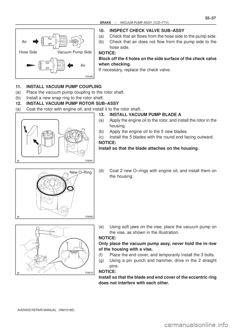
10. INSPECT CHECK VALVE SUB±ASSY
(a) Check that air flows from the hose side to the pump side.
(b) Check that air does not flow from the pump side to the
hose side.
NOTICE:
Block off the 4 holes on the side surface of the check valve
when checking.
If necessary, replace the check valve.
11. INSTALL VACUUM PUMP COUPLING
(a) Place the vacuum pump coupling to the rotor shaft.
(b) Install a new snap ring to the rotor shaft.
12. INSTALL VACUUM PUMP ROTOR SUB±ASSY
(a) Coat the rotor with engine oil, and install it to the rotor shaft.
13. INSTALL VACUUM PUMP BLADE A
(a) Apply the engine oil to the rotor, and install the rotor in the
housing.
(b) Apply the engine oil to the 5 new blades.
(c) Install the 5 blades with the round end facing outward.
NOTICE:
Install so that the blade attaches on the housing.
(d) Coat 2 new O±rings with engine oil, and install them on
the housing.
(e) Using soft jaws on the vise, place the vacuum pump on
the vise, as shown in the illustration.
NOTICE:
Only place the vacuum pump assy, never hold the in±low
of the housing with a vise.
(f) Place the end cover, and temporarily install the 3 bolts.
(g) Using a pin punch and hammer, drive in the 2 straight
pins.
NOTICE:
Install so that the blade and end cover of the eccentric ring
does not interfere with each other.
Page 2646 of 5135
C99456
GrooveNeutral
Basic Line
C99457
C99458
C62665
������D31060
± AUTOMATIC TRANSMISSION / TRANSPARK/NEUTRAL POSITION SWITCH ASSY (ATM)
40±5
AVENSIS REPAIR MANUAL (RM1018E)
(7) Align the groove with the neutral basic line.
(8) Hold the switch in position and tighten the 2 bolts.
Torque: 5.4 N�m (55 kgf�cm, 48 in.�lbf)
(9) Using a screwdriver, stake the nut with the lock
plate.
(10) Install the control shaft lever, washer and nut.
Torque: 13 N�m (130 kgf�cm, 9 ft�lbf)
(11) Connect the park/neutral position switch connector.
(b) U341E:
(1) Install the park/neutral position switch to the manual
valve shaft.
(2) Temporarily install the 2 bolts.
(3) Place a new lock plate and tighten the nut.
Torque: 6.9 N�m (70 kgf�cm, 61 in.�lbf)
(4) Temporarily install the control shaft lever.