Page 1992 of 5135
1306Z±01
A79155
A80093
A79158
±
INTAKE TURBOCHARGER SUB±ASSY(1CD±FTV)
13±11
AVENSIS REPAIR MANUAL (RM1018E)
REPLACEMENT
1.REMOVE ENGINE UNDER COVER SUB±ASSY NO.1
2.DRAIN ENGINE COOLANT(See page 16±44)
3.REMOVE RADIATOR SUPPORT OPENING COVER
4.REMOVE ENGINE COVER NO.1
(a)Remove the 5 nuts and the engine cover.
5.REMOVE VACUUM RESERVOIR SUB±ASSY
(a)Disconnect the 2 vacuum hoses and the connector.
(b)Remove the 2 bolts and the vacuum reservoir.
6.REMOVE AIR CLEANER ASSY
(a)Disconnect the PCV hose and the connector.
(b)Remove the air cleaner cap with the air cleaner hose.
(c)Remove the air cleaner filter element.
(d)Remove the 3 bolts and the air cleaner case. 7.REMOVE INTERCOOLER AIR HOSE
(a)Remove the 3 bolts and nut, separate the air tube No.1.
(b)Loosen the hose clamp bolts and remove the air hoseNo.1.
8.REMOVE FUEL FILTER ASSY(See page 11±82) 9. SEPARATE HEATER PUMP ASSY (W/ COLD AREA)
(a) Remove the nut and disconnect the connector.
(b) Separate the heater pump.
Page 2028 of 5135
141CI±01
A78459
A60622
A79324
A76713
±
ENGINE MECHANICAL CHAIN SUB±ASSY(1ZZ±FE/3ZZ±FE)
14±49
AVENSIS REPAIR MANUAL (RM1018E)
REPLACEMENT
1.REMOVE RADIATOR SUPPORT OPENING COVER (See page 14±27)
2.REMOVE ENGINE ROOM COVER SIDE (See page 14±27)
3.REMOVE FRONT WHEEL RH
4.REMOVE ENGINE UNDER COVER SUB±ASSY NO.1 (See page 14±27)
5.REMOVE ENGINE UNDER COVER RH (See page 14±27)
6.DRAIN ENGINE COOLANT (See page 16±7)
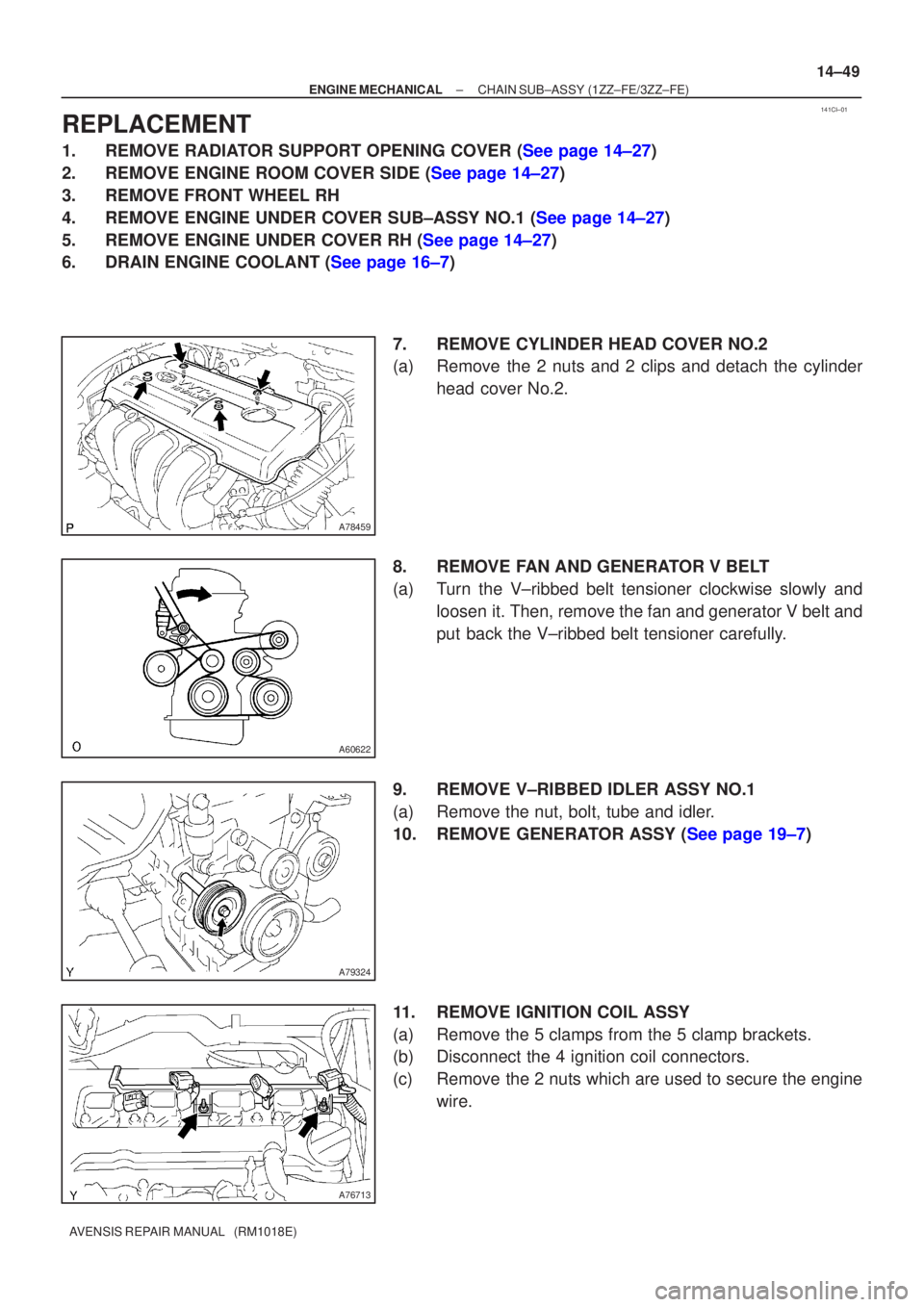
7.REMOVE CYLINDER HEAD COVER NO.2
(a)Remove the 2 nuts and 2 clips and detach the cylinderhead cover No.2.
8.REMOVE FAN AND GENERATOR V BELT
(a)Turn the V±ribbed belt tensioner clockwise slowly and loosen it. Then, remove the fan and generator V belt and
put back the V±ribbed belt tensioner carefully.
9.REMOVE V±RIBBED IDLER ASSY NO.1
(a)Remove the nut, bolt, tube and idler.
10.REMOVE GENERATOR ASSY (See page 19±7)
11. REMOVE IGNITION COIL ASSY
(a) Remove the 5 clamps from the 5 clamp brackets.
(b) Disconnect the 4 ignition coil connectors.
(c) Remove the 2 nuts which are used to secure the engine wire.
Page 2044 of 5135
A78516
A78459
14±28
±
ENGINE MECHANICAL PARTIAL ENGINE ASSY(1ZZ±FE/3ZZ±FE)
AVENSIS REPAIR MANUAL (RM1018E)
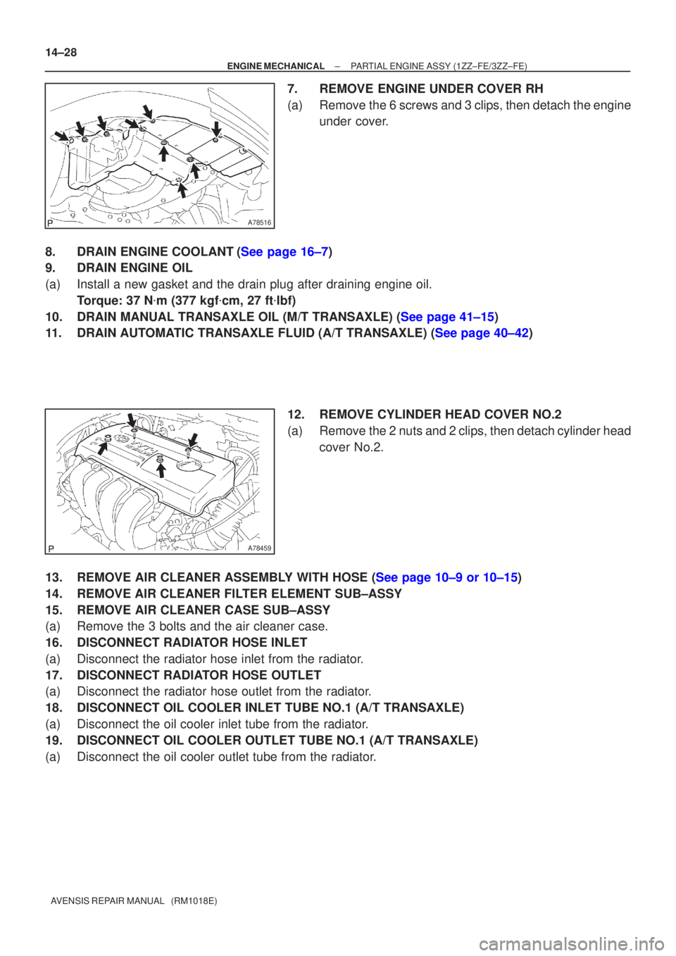
7.REMOVE ENGINE UNDER COVER RH
(a)Remove the 6 screws and 3 clips, then detach the engine under cover.
8.DRAIN ENGINE COOLANT(See page 16±7)
9. DRAIN ENGINE OIL
(a) Install a new gasket and the drain plug after draining engine oil. Torque: 37 N �m (377 kgf �cm, 27 ft �lbf)
10.DRAIN MANUAL TRANSAXLE OIL (M/T TRANSAXLE) (See page 41±15)
11.DRAIN AUTOMATIC TRANSAXLE FLUID (A/T TRANSAXLE) (See page 40±42)
12. REMOVE CYLINDER HEAD COVER NO.2
(a) Remove the 2 nuts and 2 clips, then detach cylinder headcover No.2.
13.REMOVE AIR CLEANER ASSEMBLY WITH HOSE (See page 10±9 or 10±15)
14. REMOVE AIR CLEANER FILTER ELEMENT SUB±ASSY
15. REMOVE AIR CLEANER CASE SUB±ASSY
(a) Remove the 3 bolts and the air cleaner case.
16. DISCONNECT RADIATOR HOSE INLET
(a) Disconnect the radiator hose inlet from the radiator.
17. DISCONNECT RADIATOR HOSE OUTLET
(a) Disconnect the radiator hose outlet from the radiator.
18. DISCONNECT OIL COOLER INLET TUBE NO.1 (A/T TRANSAXLE)
(a) Disconnect the oil cooler inlet tube from the radiator.
19. DISCONNECT OIL COOLER OUTLET TUBE NO.1 (A/T TRANSAXLE)
(a) Disconnect the oil cooler outlet tube from the radiator.
Page 2069 of 5135
141BF±01
A77281
A77301
±
ENGINE MECHANICAL PARTIAL ENGINE ASSY(1AZ±FE)
14±121
AVENSIS REPAIR MANUAL (RM1018E)
REPLACEMENT
1.DISCHARGE FUEL SYSTEM PRESSURE (See page 11±19)
2.REMOVE FRONT WHEELS
3.REMOVE RADIATOR SUPPORT OPENING COVER
4.REMOVE ENGINE ROOM COVER SIDE
5.REMOVE ENGINE UNDER COVER RH
6.REMOVE ENGINE UNDER COVER LH
7.DRAIN COOLANT (See page 16±19)
8.DRAIN ENGINE OIL
(a)Install a new gasket and the drain plug after draining engine oil.
Torque: 25 N �m (255 kgf �cm,18 ft �lbf)
9.DRAIN MANUAL TRANSAXLE OIL (M/T TRANSAXLE) Torque: 49 N �m (500 kgf �cm,36 ft �lbf)
10.DRAIN AUTOMATIC TRANSAXLE FLUID (A/T TRANSAXLE) (See page 40±2)
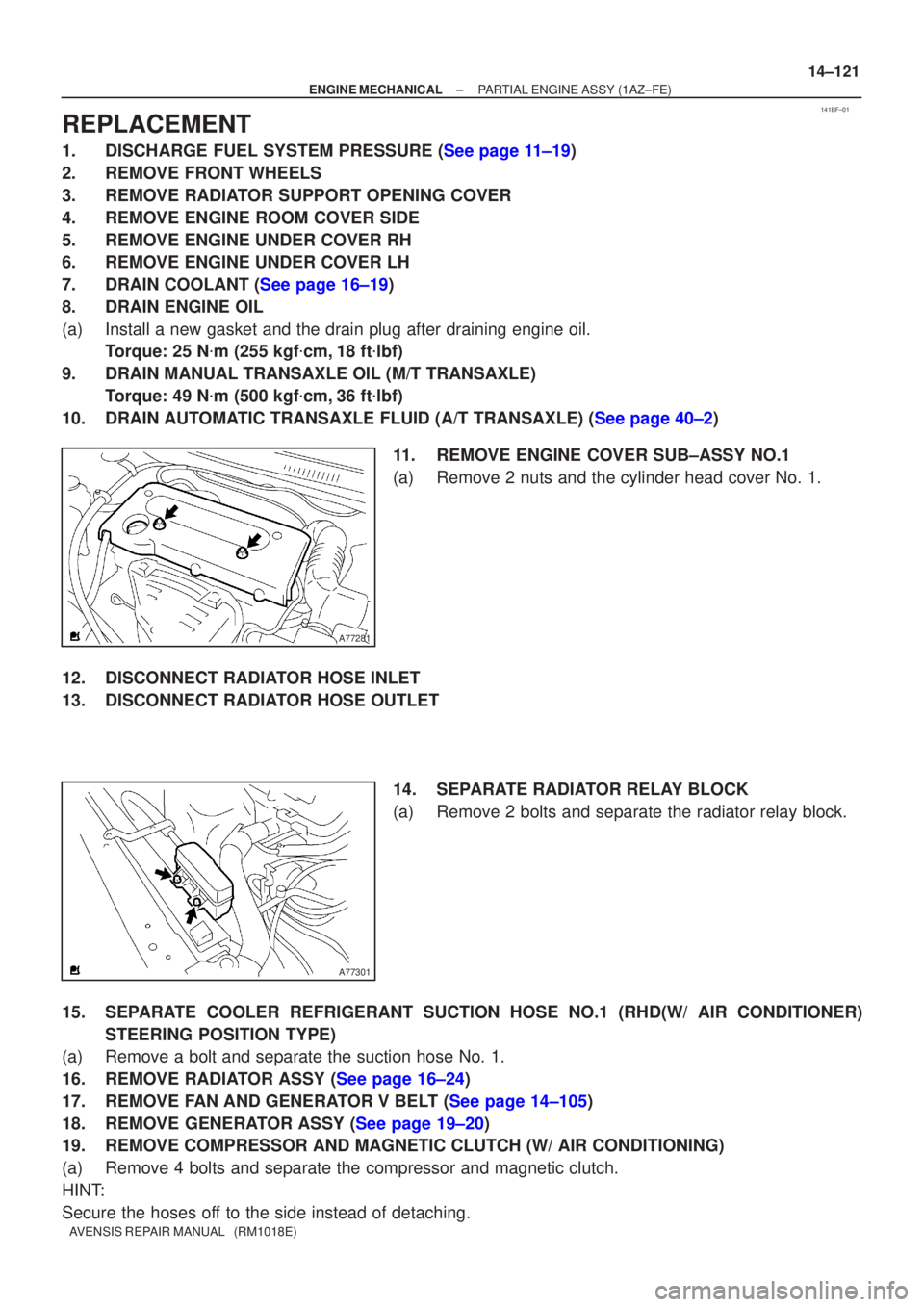
11.REMOVE ENGINE COVER SUB±ASSY NO.1
(a)Remove 2 nuts and the cylinder head cover No. 1.
12.DISCONNECT RADIATOR HOSE INLET
13.DISCONNECT RADIATOR HOSE OUTLET 14.SEPARATE RADIATOR RELAY BLOCK
(a)Remove 2 bolts and separate the radiator relay block.
15.SEPARATE COOLER REFRIGERANT SUCTION HOSE NO.1 (RHD(W/ AIR CONDITIONER) STEERING POSITION TYPE)
(a)Remove a bolt and separate the suction hose No. 1.
16.REMOVE RADIATOR ASSY (See page 16±24)
17.REMOVE FAN AND GENERATOR V BELT (See page 14±105)
18.REMOVE GENERATOR ASSY (See page 19±20)
19. REMOVE COMPRESSOR AND MAGNETIC CLUTCH (W/ AIR CONDITIONING)
(a) Remove 4 bolts and separate the compressor and magnetic clutch.
HINT:
Secure the hoses off to the side instead of detaching.
Page 2108 of 5135
141CM±01
A78459
A78461
1ZZ±FE
A78497
3ZZ±FE
±
ENGINE MECHANICAL CYLINDER HEAD GASKET(1ZZ±FE/3ZZ±FE)
14±81
AVENSIS REPAIR MANUAL (RM1018E)
REPLACEMENT
1.DISCHARGE FUEL SYSTEM PRESSURE(See page 11±1)
2.REMOVE RADIATOR SUPPORT OPENING COVER (See page 14±27)
3.REMOVE ENGINE ROOM COVER SIDE (See page 14±27)
4.REMOVE FRONT WHEEL RH
5.REMOVE ENGINE UNDER COVER SUB±ASSY NO.1 (See page 14±27)
6.REMOVE ENGINE UNDER COVER RH (See page 14±27)
7.DRAIN ENGINE COOLANT(See page 16±7)
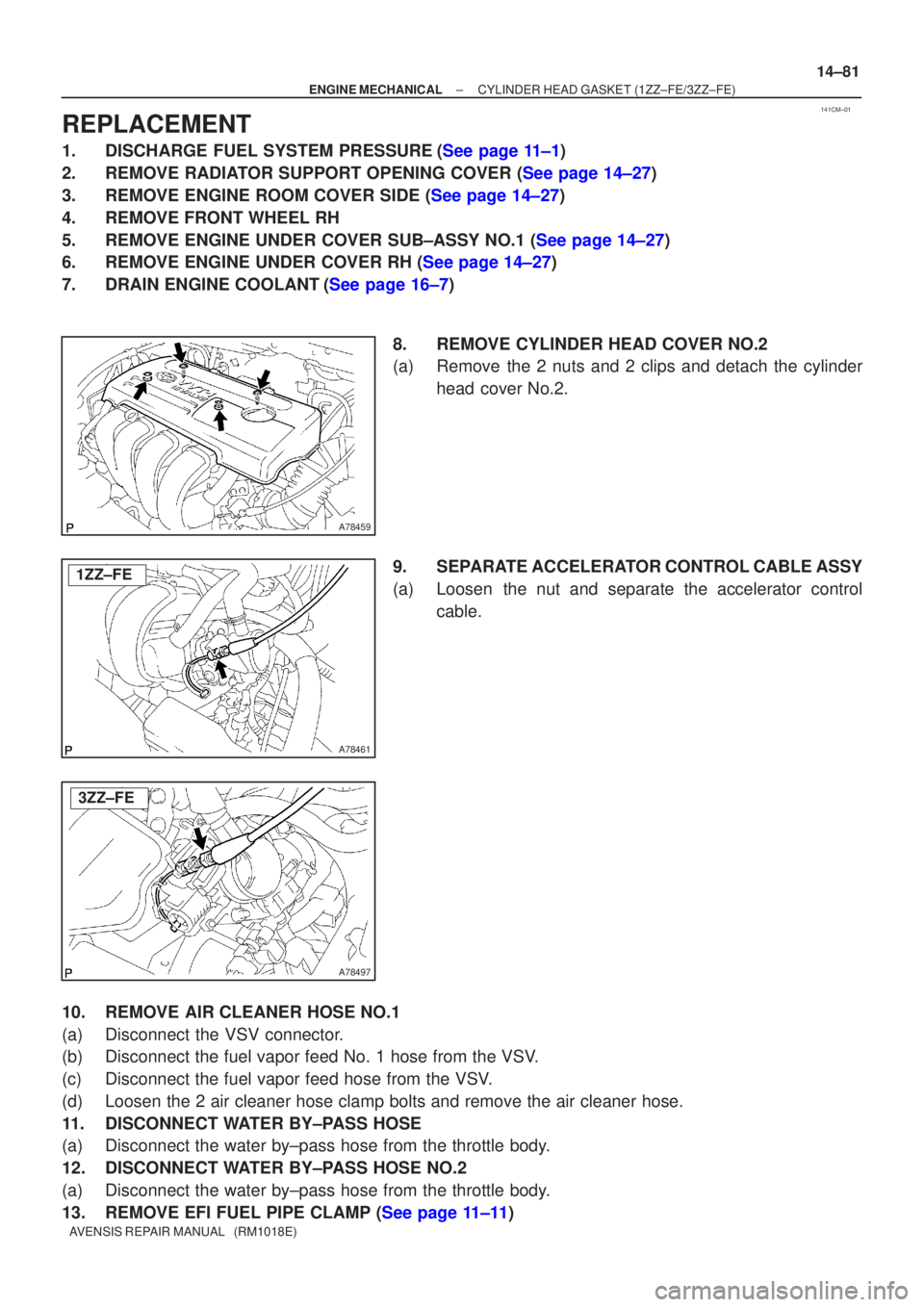
8.REMOVE CYLINDER HEAD COVER NO.2
(a)Remove the 2 nuts and 2 clips and detach the cylinderhead cover No.2.
9.SEPARATE ACCELERATOR CONTROL CABLE ASSY
(a)Loosen the nut and separate the accelerator control cable.
10.REMOVE AIR CLEANER HOSE NO.1
(a)Disconnect the VSV connector.
(b)Disconnect the fuel vapor feed No. 1 hose from the VSV.
(c)Disconnect the fuel vapor feed hose from the VSV.
(d)Loosen the 2 air cleaner hose clamp bolts and remove the air cleaner hos\
e.
11.DISCONNECT WATER BY±PASS HOSE
(a)Disconnect the water by±pass hose from the throttle body.
12.DISCONNECT WATER BY±PASS HOSE NO.2
(a)Disconnect the water by±pass hose from the throttle body.
13.REMOVE EFI FUEL PIPE CLAMP (See page 11±11)
Page 2145 of 5135
141BB±01
A77292
A77299
14±160
±
ENGINE MECHANICAL CYLINDER HEAD GASKET (1AZ±FE)
AVENSIS REPAIR MANUAL (RM1018E)
REPLACEMENT
1.DISCHARGE FUEL SYSTEM PRESSURE (See page 11±15)
2. REMOVE FRONT WHEEL RH
3. REMOVE RADIATOR SUPPORT OPENING COVER
4. REMOVE ENGINE ROOM COVER SIDE
5. REMOVE ENGINE UNDER COVER RH
6. REMOVE ENGINE UNDER COVER LH
7.DRAIN COOLANT (See page 16±19)
8. DRAIN ENGINE OIL
(a) Install a new gasket and the drain plug after draining engine oil. Torque: 25 N �m (255 kgf �cm, 18 ft �lbf)
9.REMOVE ENGINE COVER SUB±ASSY NO.1 (See page 14±121)
10.REMOVE FAN AND GENERATOR V BELT (See page 14±105) SST 09249±63010
11.REMOVE GENERATOR ASSY (See page 19±20)
12.REMOVE EXHAUST PIPE ASSY FRONT (See page 15±7)
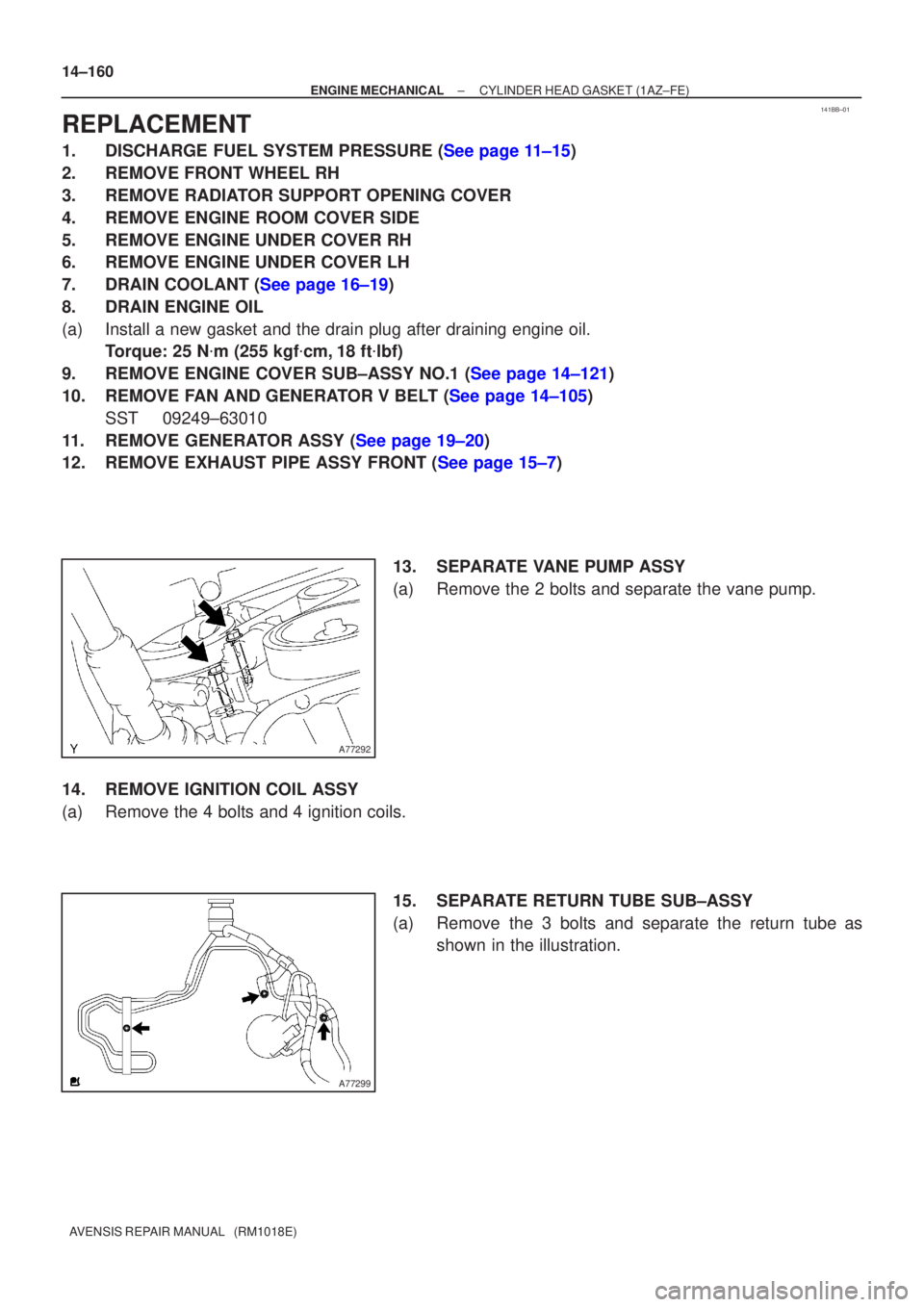
13. SEPARATE VANE PUMP ASSY
(a) Remove the 2 bolts and separate the vane pump.
14. REMOVE IGNITION COIL ASSY
(a) Remove the 4 bolts and 4 ignition coils. 15. SEPARATE RETURN TUBE SUB±ASSY
(a) Remove the 3 bolts and separate the return tube asshown in the illustration.
Page 2160 of 5135
141B8±01
A77281
A77292
A77299
±
ENGINE MECHANICAL CHAIN SUB±ASSY(1AZ±FE)
14±139
AVENSIS REPAIR MANUAL (RM1018E)
REPLACEMENT
1.REMOVE FRONT WHEEL RH
2.REMOVE RADIATOR SUPPORT OPENING COVER
3.REMOVE ENGINE ROOM COVER SIDE
4.REMOVE ENGINE UNDER COVER RH
5.REMOVE ENGINE UNDER COVER LH
6.DRAIN ENGINE OIL
(a)Install a new gasket and the drain plug after draining the engine oil.
Torque: 25 N �m (255 kgf �cm,18 ft �lbf)
7.REMOVE ENGINE COVER SUB±ASSY NO.1
(a)Remove the 2 nuts and the engine cover No. 1.
8.REMOVE FAN AND GENERATOR V BELT (See page 14±105) SST 09249±63010
9.REMOVE GENERATOR ASSY (See page 19±20)
10.REMOVE EXHAUST PIPE ASSY FRONT (See page 15±7)
11. SEPARATE VANE PUMP ASSY
(a) Remove the 2 through bolts and separate the vane pump.
12. SEPARATE RETURN TUBE SUB±ASSY
(a) Remove 3 bolts and separate the return tube as shownin the illustration.
Page 2181 of 5135
141BD±01
A77339
A77292
14±222
±
ENGINE MECHANICAL CHAIN SUB±ASSY(1AZ±FSE)
AVENSIS REPAIR MANUAL (RM1018E)
REPLACEMENT
1.DISCHARGE FUEL SYSTEM PRESSURE (See page 11±30)
2.REMOVE FRONT WHEEL RH
3.REMOVE RADIATOR SUPPORT OPENING COVER
4.REMOVE ENGINE ROOM COVER SIDE
5.REMOVE ENGINE UNDER COVER RH
6.REMOVE ENGINE UNDER COVER LH
7.DRAIN ENGINE OIL
(a)Install a new gasket and the drain plug after draining engine oil. Torque: 25 N �m (255 kgf �cm,18 ft �lbf)
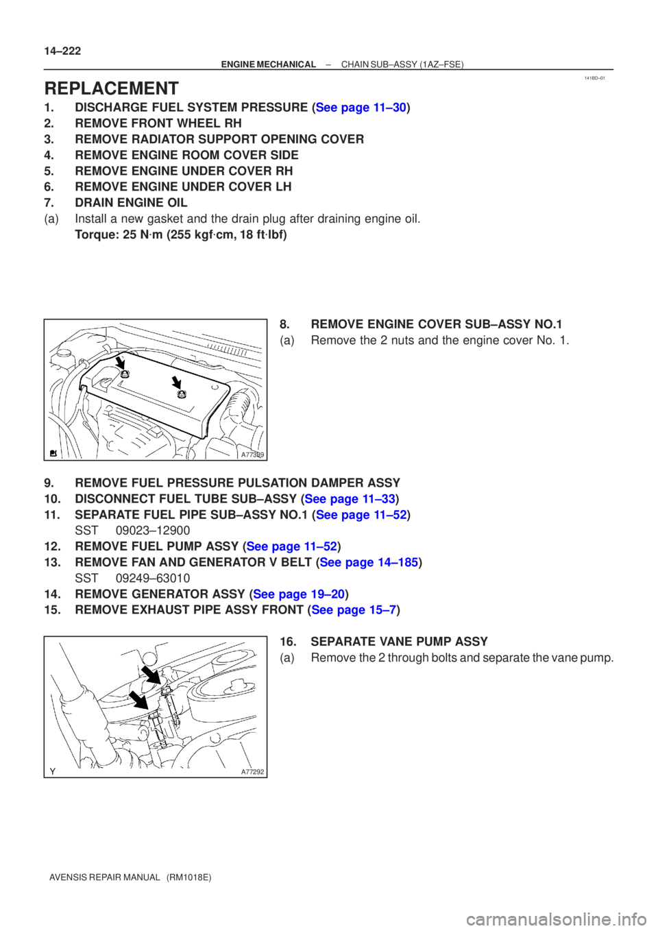
8.REMOVE ENGINE COVER SUB±ASSY NO.1
(a)Remove the 2 nuts and the engine cover No. 1.
9.REMOVE FUEL PRESSURE PULSATION DAMPER ASSY
10.DISCONNECT FUEL TUBE SUB±ASSY (See page 11±33)
11.SEPARATE FUEL PIPE SUB±ASSY NO.1 (See page 11±52) SST 09023±12900
12.REMOVE FUEL PUMP ASSY (See page 11±52)
13.REMOVE FAN AND GENERATOR V BELT (See page 14±185) SST 09249±63010
14.REMOVE GENERATOR ASSY (See page 19±20)
15.REMOVE EXHAUST PIPE ASSY FRONT (See page 15±7)
16. SEPARATE VANE PUMP ASSY
(a) Remove the 2 through bolts and separate the vane pump.