Page 2615 of 5135
320W0±01
G23181
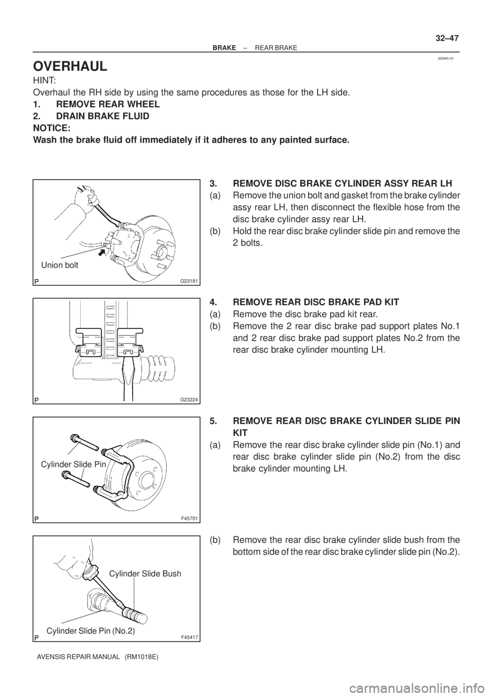
Union bolt
G23224
F45701
Cylinder Slide Pin
F45417
Cylinder Slide Bush
Cylinder Slide Pin (No.2)
± BRAKEREAR BRAKE
32±47
AVENSIS REPAIR MANUAL (RM1018E)
OVERHAUL
HINT:
Overhaul the RH side by using the same procedures as those for the LH side.
1. REMOVE REAR WHEEL
2. DRAIN BRAKE FLUID
NOTICE:
Wash the brake fluid off immediately if it adheres to any painted surface.
3. REMOVE DISC BRAKE CYLINDER ASSY REAR LH
(a) Remove the union bolt and gasket from the brake cylinder
assy rear LH, then disconnect the flexible hose from the
disc brake cylinder assy rear LH.
(b) Hold the rear disc brake cylinder slide pin and remove the
2 bolts.
4. REMOVE REAR DISC BRAKE PAD KIT
(a) Remove the disc brake pad kit rear.
(b) Remove the 2 rear disc brake pad support plates No.1
and 2 rear disc brake pad support plates No.2 from the
rear disc brake cylinder mounting LH.
5. REMOVE REAR DISC BRAKE CYLINDER SLIDE PIN
KIT
(a) Remove the rear disc brake cylinder slide pin (No.1) and
rear disc brake cylinder slide pin (No.2) from the disc
brake cylinder mounting LH.
(b) Remove the rear disc brake cylinder slide bush from the
bottom side of the rear disc brake cylinder slide pin (No.2).
Page 2622 of 5135
320W1±01
F45421
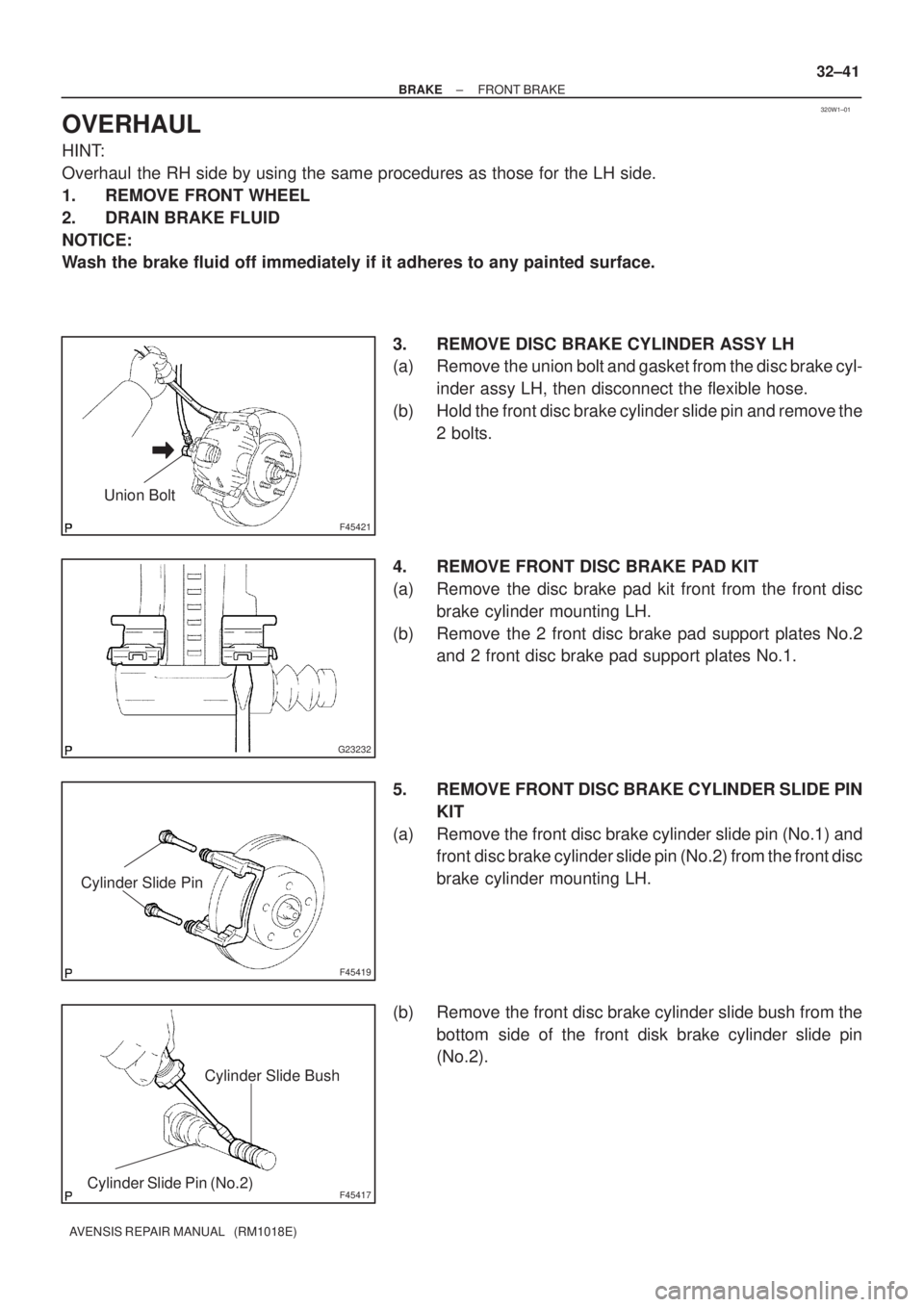
Union Bolt
G23232
F45419
Cylinder Slide Pin
F45417
Cylinder Slide Bush
Cylinder Slide Pin (No.2)
± BRAKEFRONT BRAKE
32±41
AVENSIS REPAIR MANUAL (RM1018E)
OVERHAUL
HINT:
Overhaul the RH side by using the same procedures as those for the LH side.
1. REMOVE FRONT WHEEL
2. DRAIN BRAKE FLUID
NOTICE:
Wash the brake fluid off immediately if it adheres to any painted surface.
3. REMOVE DISC BRAKE CYLINDER ASSY LH
(a) Remove the union bolt and gasket from the disc brake cyl-
inder assy LH, then disconnect the flexible hose.
(b) Hold the front disc brake cylinder slide pin and remove the
2 bolts.
4. REMOVE FRONT DISC BRAKE PAD KIT
(a) Remove the disc brake pad kit front from the front disc
brake cylinder mounting LH.
(b) Remove the 2 front disc brake pad support plates No.2
and 2 front disc brake pad support plates No.1.
5. REMOVE FRONT DISC BRAKE CYLINDER SLIDE PIN
KIT
(a) Remove the front disc brake cylinder slide pin (No.1) and
front disc brake cylinder slide pin (No.2) from the front disc
brake cylinder mounting LH.
(b) Remove the front disc brake cylinder slide bush from the
bottom side of the front disk brake cylinder slide pin
(No.2).
Page 2675 of 5135
400DD±02
C83111
AT0103
D25591
C50009
40±52
± AUTOMATIC TRANSMISSION / TRANSTRANSMISSION WIRE (U241E)
AVENSIS REPAIR MANUAL (RM1018E)
TRANSMISSION WIRE (U241E)
REPLACEMENT
1. REMOVE ENGINE UNDER COVER LH
2. DRAIN AUTOMATIC TRANSAXLE FLUID
(a) Remove the drain plug, gasket and drain ATF.
(b) Install a new gasket and the drain plug.
Torque: 49 N�m (500 kgf�cm, 36 ft�lbf)
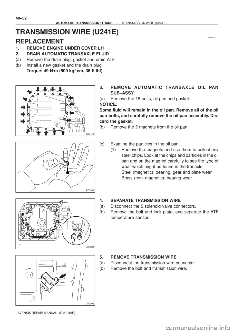
3. REMOVE AUTOMATIC TRANSAXLE OIL PAN
SUB±ASSY
(a) Remove the 18 bolts, oil pan and gasket.
NOTICE:
Some fluid will remain in the oil pan. Remove all of the oil
pan bolts, and carefully remove the oil pan assembly. Dis-
card the gasket.
(b) Remove the 2 magnets from the oil pan.
(c) Examine the particles in the oil pan.
(1) Remove the magnets and use them to collect any
steel chips. Look at the chips and particles in the oil
pan and on the magnet carefully to see the type of
wear which might be found in the tranaxle.
Steel (magnetic): bearing, gear and plate wear
Brass (non±magnetic): bearing wear
4. SEPARATE TRANSMISSION WIRE
(a) Disconnect the 5 solenoid valve connectors.
(b) Remove the bolt and lock plate, and separate the ATF
temperature sensor.
5. REMOVE TRANSMISSION WIRE
(a) Disconnect the transmission wire connector.
(b) Remove the bolt and transmission wire.
Page 2679 of 5135
400DC±02
C83111
AT0103
D25591
D09179
± AUTOMATIC TRANSMISSION / TRANSTRANSMISSION VALVE BODY ASSY (U241E)
40±47
AVENSIS REPAIR MANUAL (RM1018E)
TRANSMISSION VALVE BODY ASSY (U241E)
REPLACEMENT
1. REMOVE ENGINE UNDER COVER LH
2. DRAIN AUTOMATIC TRANSAXLE FLUID
(a) Remove the drain plug, gasket and drain ATF.
(b) Install a new gasket and the drain plug.
Torque: 49 N�m (500 kgf�cm, 36 ft�lbf)
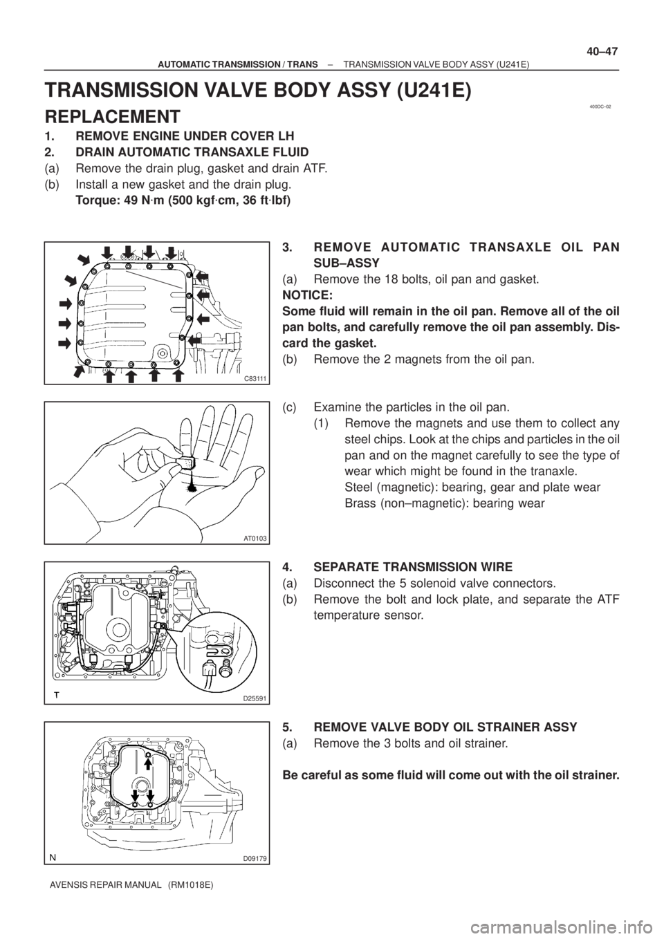
3. REMOVE AUTOMATIC TRANSAXLE OIL PAN
SUB±ASSY
(a) Remove the 18 bolts, oil pan and gasket.
NOTICE:
Some fluid will remain in the oil pan. Remove all of the oil
pan bolts, and carefully remove the oil pan assembly. Dis-
card the gasket.
(b) Remove the 2 magnets from the oil pan.
(c) Examine the particles in the oil pan.
(1) Remove the magnets and use them to collect any
steel chips. Look at the chips and particles in the oil
pan and on the magnet carefully to see the type of
wear which might be found in the tranaxle.
Steel (magnetic): bearing, gear and plate wear
Brass (non±magnetic): bearing wear
4. SEPARATE TRANSMISSION WIRE
(a) Disconnect the 5 solenoid valve connectors.
(b) Remove the bolt and lock plate, and separate the ATF
temperature sensor.
5. REMOVE VALVE BODY OIL STRAINER ASSY
(a) Remove the 3 bolts and oil strainer.
Be careful as some fluid will come out with the oil strainer.
Page 2683 of 5135
40123±01
C62684
AT0103
D30631
D05904O±Ring
40±42
± AUTOMATIC TRANSMISSION / TRANSTRANSMISSION VALVE BODY ASSY (U341E)
AVENSIS REPAIR MANUAL (RM1018E)
TRANSMISSION VALVE BODY ASSY (U341E)
REPLACEMENT
1. REMOVE ENGINE UNDER COVER LH
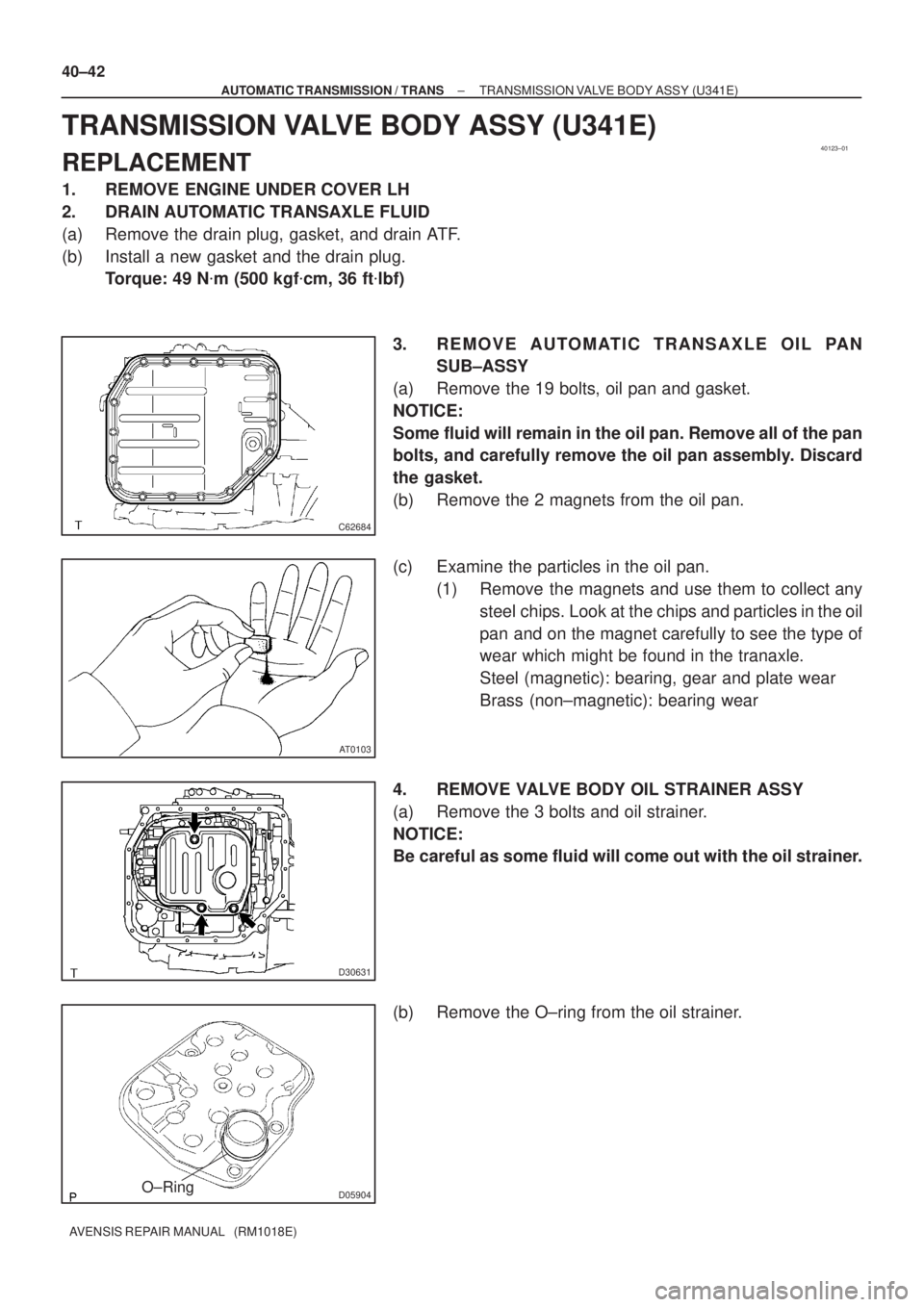
2. DRAIN AUTOMATIC TRANSAXLE FLUID
(a) Remove the drain plug, gasket, and drain ATF.
(b) Install a new gasket and the drain plug.
Torque: 49 N�m (500 kgf�cm, 36 ft�lbf)
3. REMOVE AUTOMATIC TRANSAXLE OIL PAN
SUB±ASSY
(a) Remove the 19 bolts, oil pan and gasket.
NOTICE:
Some fluid will remain in the oil pan. Remove all of the pan
bolts, and carefully remove the oil pan assembly. Discard
the gasket.
(b) Remove the 2 magnets from the oil pan.
(c) Examine the particles in the oil pan.
(1) Remove the magnets and use them to collect any
steel chips. Look at the chips and particles in the oil
pan and on the magnet carefully to see the type of
wear which might be found in the tranaxle.
Steel (magnetic): bearing, gear and plate wear
Brass (non±magnetic): bearing wear
4. REMOVE VALVE BODY OIL STRAINER ASSY
(a) Remove the 3 bolts and oil strainer.
NOTICE:
Be careful as some fluid will come out with the oil strainer.
(b) Remove the O±ring from the oil strainer.
Page 2694 of 5135
D30342
D30343
D30346
D30344
40±26
±
AUTOMATIC TRANSMISSION / TRANS AUTOMATIC TRANSAXLE ASSY (U241E)
AVENSIS REPAIR MANUAL (RM1018E)
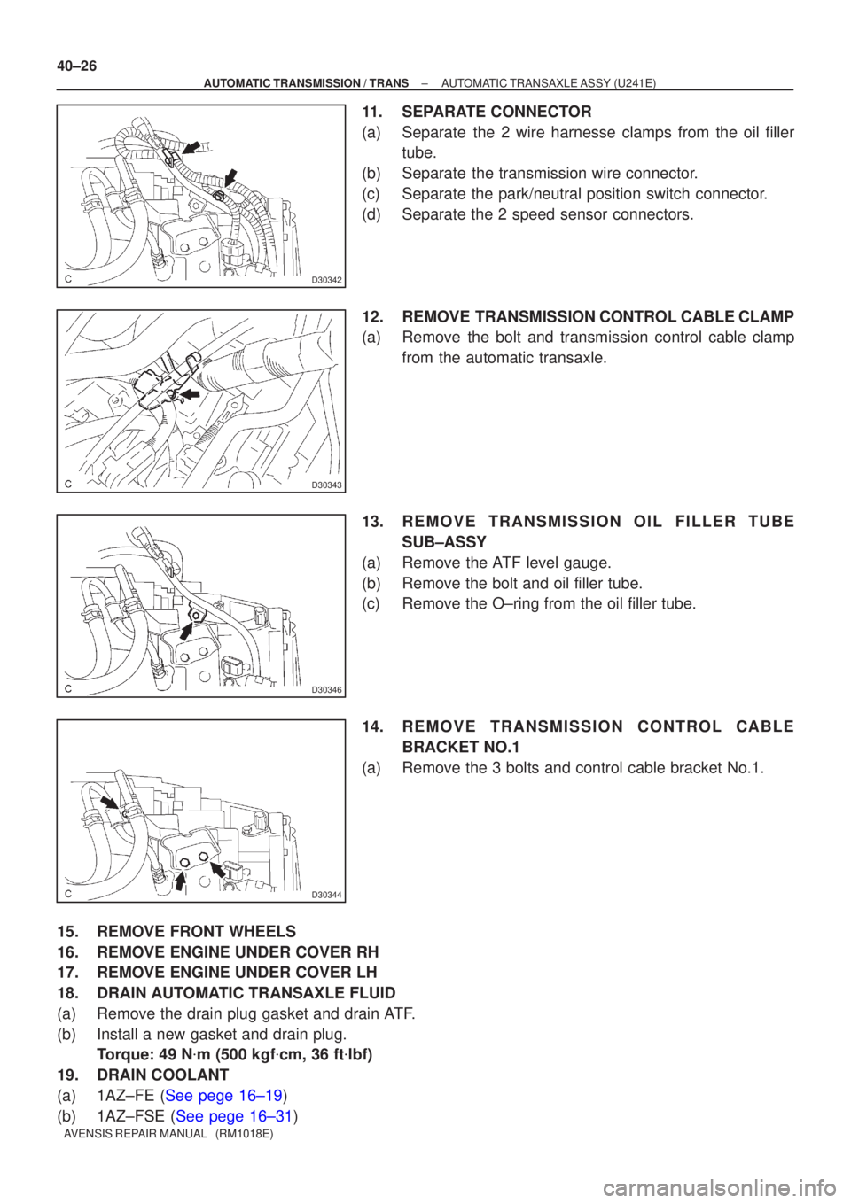
11. SEPARATE CONNECTOR
(a) Separate the 2 wire harnesse clamps from the oil filler tube.
(b) Separate the transmission wire connector.
(c) Separate the park/neutral position switch connector.
(d) Separate the 2 speed sensor connectors.
12. REMOVE TRANSMISSION CONTROL CABLE CLAMP
(a) Remove the bolt and transmission control cable clamp from the automatic transaxle.
13. REMOVE TRANSMISSION OIL FILLER TUBE SUB±ASSY
(a) Remove the ATF level gauge.
(b) Remove the bolt and oil filler tube.
(c) Remove the O±ring from the oil filler tube.
14. REMOVE TRANSMISSION CONTROL CABLE BRACKET NO.1
(a) Remove the 3 bolts and control cable bracket No.1.
15. REMOVE FRONT WHEELS
16. REMOVE ENGINE UNDER COVER RH
17. REMOVE ENGINE UNDER COVER LH
18. DRAIN AUTOMATIC TRANSAXLE FLUID
(a) Remove the drain plug gasket and drain ATF.
(b) Install a new gasket and drain plug. Torque: 49 N �m (500 kgf �cm, 36 ft �lbf)
19. DRAIN COOLANT
(a)1AZ±FE (See pege 16±19)
(b)1AZ±FSE (See pege 16±31)
Page 2708 of 5135
C91880
C80991
C91884
40±12
±
AUTOMATIC TRANSMISSION / TRANS AUTOMATIC TRANSAXLE ASSY (U341E)
AVENSIS REPAIR MANUAL (RM1018E)
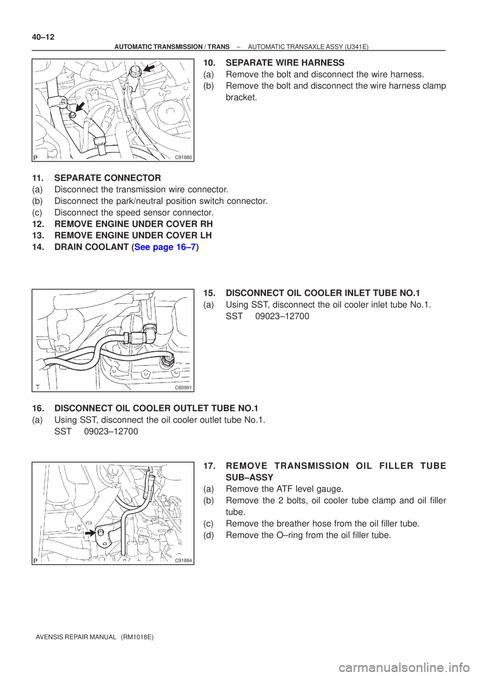
10. SEPARATE WIRE HARNESS
(a) Remove the bolt and disconnect the wire harness.
(b) Remove the bolt and disconnect the wire harness clamp bracket.
11. SEPARATE CONNECTOR
(a) Disconnect the transmission wire connector.
(b) Disconnect the park/neutral position switch connector.
(c) Disconnect the speed sensor connector.
12. REMOVE ENGINE UNDER COVER RH
13. REMOVE ENGINE UNDER COVER LH
14.DRAIN COOLANT (See page 16±7) 15. DISCONNECT OIL COOLER INLET TUBE NO.1
(a) Using SST, disconnect the oil cooler inlet tube No.1.SST 09023±12700
16. DISCONNECT OIL COOLER OUTLET TUBE NO.1
(a) Using SST, disconnect the oil cooler outlet tube No.1. SST 09023±12700
17. REMOVE TRANSMISSION OIL FILLER TUBESUB±ASSY
(a) Remove the ATF level gauge.
(b) Remove the 2 bolts, oil cooler tube clamp and oil filler
tube.
(c) Remove the breather hose from the oil filler tube.
(d) Remove the O±ring from the oil filler tube.
Page 2709 of 5135
C91882
C94723
D25372
±
AUTOMATIC TRANSMISSION / TRANS AUTOMATIC TRANSAXLE ASSY (U341E)
40±13
AVENSIS REPAIR MANUAL (RM1018E)
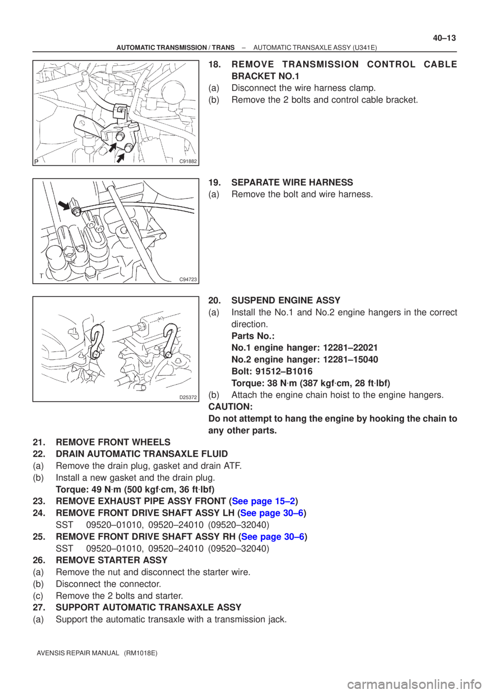
18. REMOVE TRANSMISSION CONTROL CABLE
BRACKET NO.1
(a) Disconnect the wire harness clamp.
(b) Remove the 2 bolts and control cable bracket.
19. SEPARATE WIRE HARNESS
(a) Remove the bolt and wire harness.
20. SUSPEND ENGINE ASSY
(a) Install the No.1 and No.2 engine hangers in the correct
direction.
Parts No.:
No.1 engine hanger: 12281±22021
No.2 engine hanger: 12281±15040
Bolt: 91512±B1016
Torque: 38 N �m (387 kgf �cm, 28 ft �lbf)
(b) Attach the engine chain hoist to the engine hangers.
CAUTION:
Do not attempt to hang the engine by hooking the chain to
any other parts.
21. REMOVE FRONT WHEELS
22. DRAIN AUTOMATIC TRANSAXLE FLUID
(a) Remove the drain plug, gasket and drain ATF.
(b) Install a new gasket and the drain plug. Torque: 49 N �m (500 kgf �cm, 36 ft �lbf)
23.REMOVE EXHAUST PIPE ASSY FRONT (See page 15±2)
24.REMOVE FRONT DRIVE SHAFT ASSY LH (See page 30±6)
SST 09520±01010, 09520±24010 (09520±32040)
25.REMOVE FRONT DRIVE SHAFT ASSY RH (See page 30±6) SST 09520±01010, 09520±24010 (09520±32040)
26. REMOVE STARTER ASSY
(a) Remove the nut and disconnect the starter wire.
(b) Disconnect the connector.
(c) Remove the 2 bolts and starter.
27. SUPPORT AUTOMATIC TRANSAXLE ASSY
(a) Support the automatic transaxle with a transmission jack.