Page 2427 of 5135
160MF±01
A79171
A79172
10�10�
16±50
±
COOLING THERMOSTAT(1CD±FTV)
AVENSIS REPAIR MANUAL (RM1018E)
THERMOSTAT(1CD±FTV)
REPLACEMENT
1.REMOVE RADIATOR SUPPORT OPENING COVER
2.REMOVE ENGINE ROOM COVER SIDE
3.DRAIN ENGINE COOLANT(See page 16±44)
4.REMOVE RADIATOR RESERVE TANK ASSY
(a)Disconnect the water by±pass hose No. 1 and water by±pass hose No.\
2.
(b)Remove the 2 bolts and the reserve tank assembly.
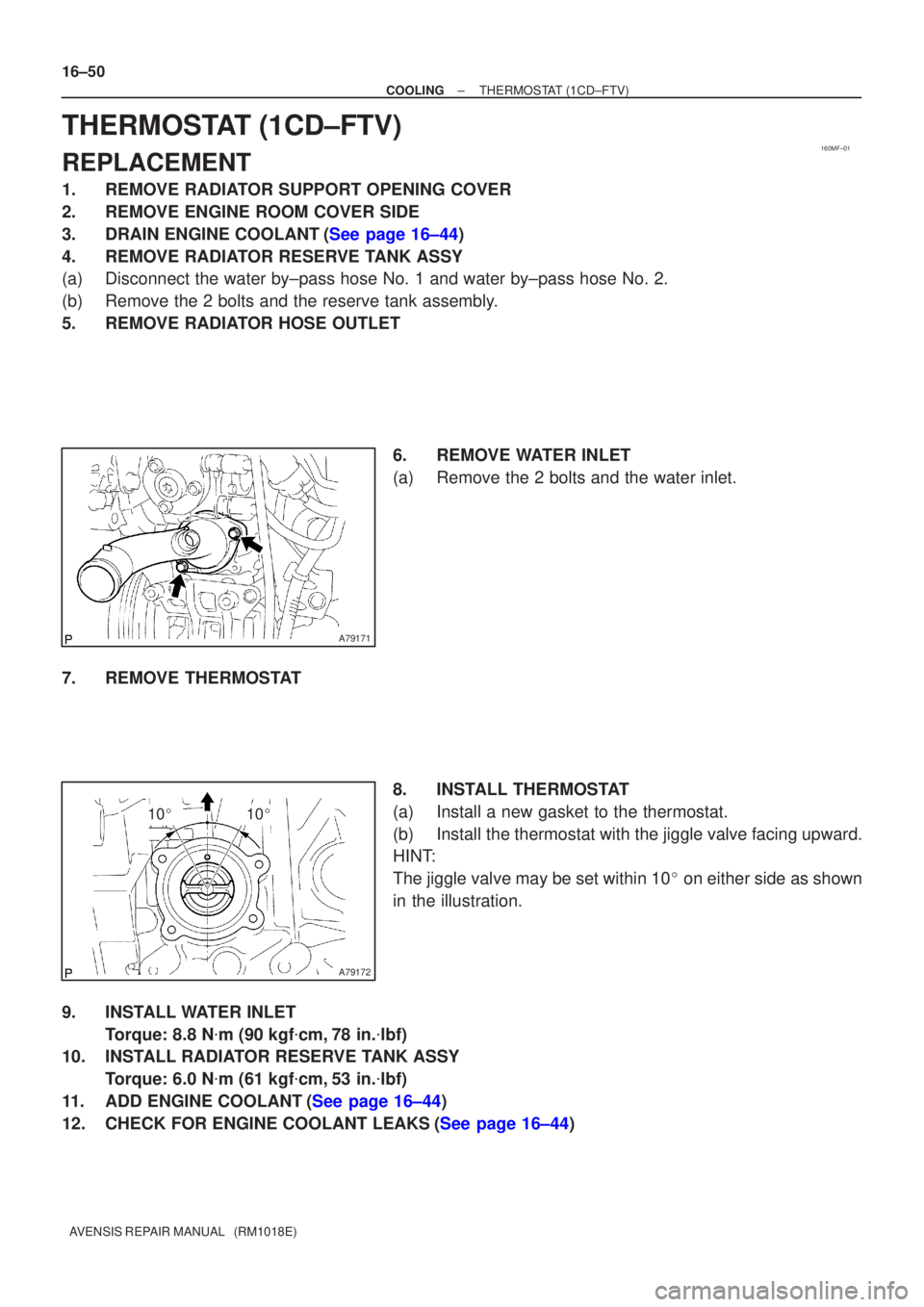
5.REMOVE RADIATOR HOSE OUTLET 6.REMOVE WATER INLET
(a)Remove the 2 bolts and the water inlet.
7.REMOVE THERMOSTAT 8.INSTALL THERMOSTAT
(a)Install a new gasket to the thermostat.
(b)Install the thermostat with the jiggle valve facing upward.
HINT:
The jiggle valve may be set within 10� on either side as shown
in the illustration.
9.INSTALL WATER INLET Torque: 8.8 N �m (90 kgf �cm,78 in. �lbf)
10.INSTALL RADIATOR RESERVE TANK ASSY
Torque: 6.0 N �m (61 kgf �cm,53 in. �lbf)
11.ADD ENGINE COOLANT(See page 16±44)
12.CHECK FOR ENGINE COOLANT LEAKS(See page 16±44)
Page 2428 of 5135

AVENSIS REPAIR MANUAL (RM1018E)
WATER PUMP ASSY(1CD±FTV)
REPLACEMENT
1.REMOVE RADIATOR SUPPORT OPENING COVER
2.REMOVE ENGINE ROOM CO")
160ME±01
A79148
SST
16±46
±
COOLING WATER PUMP ASSY(1CD±FTV)
AVENSIS REPAIR MANUAL (RM1018E)
WATER PUMP ASSY(1CD±FTV)
REPLACEMENT
1.REMOVE RADIATOR SUPPORT OPENING COVER
2.REMOVE ENGINE ROOM COVER SIDE
3.DRAIN ENGINE COOLANT(See page 16±44)
4.REMOVE FRONT WHEEL RH
5.REMOVE ENGINE UNDER COVER SUB±ASSY NO.1
6.REMOVE ENGINE UNDER COVER RH
7.REMOVE ENGINE COVER NO.1
(a)Remove the 5 nuts and the engine cover.
8.REMOVE INJECTOR DRIVER (See page 14±286)
9.REMOVE V (COOLER COMPRESSOR TO CRANKSHAFT PULLEY) BELT NO.1 (See page 14±269)
10.REMOVE GENERATOR V BELT (See page 14±269)
11.SEPARATE POWER STEERING IDLE PULLEY BRACKET (See page 14±286)
12.SEPARATE ENGINE MOUNTING INSULATOR SUB±ASSY RH(See page 14±307)
13.REMOVE CRANKSHAFT PULLEY(See page 14±307) SST 09213±54015 (90105±08076), 09330±00021, 09950±50013 (0995\
1±05010, 09952±05010, 09953±05020, 09954±05031)
14. REMOVE IDLER PULLEY SUB±ASSY
(a) Remove the bolt, the washer and the pulley.
15.REMOVE TIMING BELT NO.2 COVER(See page 14±307)
16.REMOVE TIMING BELT NO.1 COVER(See page 14±307)
17. REMOVE TIMING BELT GUIDE
18.REMOVE TRANSVERSE ENGINE ENGINE MOUNTING BRACKET(See page 14±307)
19.SET NO. 1 CYLINDER TO TDC/COMPRESSION(See page 14±307)
20.REMOVE TIMING CHAIN COVER PLATE(See page 14±307)
21.REMOVE TIMING BELT(See page 14±307)
22. REMOVE FUEL INLET PIPE SUB±ASSY(See page 11±69)
NOTICE:
After removing the fuel inlet pipe, cover the common rail
and injection pump with vinyl tape to prevent dust from be-
ing introduced.
(a) Remove the wire bracket and slide the engine wire.
(b) Using SST, remove the fuel inlet pipe from the common rail.
SST 09023±12700
(c) Using SST, remove the fuel inlet pipe from the injection pump.
SST 09023±12700
23.REMOVE INTAKE MANIFOLD INSULATOR NO.1(See page 11±69)
24. REMOVE OIL LEVEL GAGE SUB±ASSY
25.REMOVE OIL LEVEL GAGE GUIDE(See page 17±22)
26.REMOVE WATER INLET (See page 16±50)
27.DISCONNECT INJECTION PUMP TO FUEL PIPE FUEL HOSE(See page 11±69)
28.DISCONNECT INJECTION PUMP TO FUEL FILTER FUEL HOSE OR PIPE(See page 11±69)
Page 2456 of 5135

AVENSIS REPAIR MANUAL (RM1018E)
OIL COOLER ASSY(1CD±FTV)
REPLACEMENT
1.DRAIN ENGINE COOLANT(See")
170FQ±01
B14352
B14354
New O±RingNew O±Ring
B14355
17±32
±
LUBRICATION OIL COOLER ASSY(1CD±FTV)
AVENSIS REPAIR MANUAL (RM1018E)
OIL COOLER ASSY(1CD±FTV)
REPLACEMENT
1.DRAIN ENGINE COOLANT(See page 16±44)
2.DRAIN ENGINE OIL(See page 17±30)
3.REMOVE ENGINE UNDER COVER LH 4.REMOVE OIL COOLER ASSY
(a)Disconnect the 2 cooler hoses from the oil cooler.
(b)Remove the union bolt and the oil cooler.
(c)Remove the O±ring from the oil cooler.
(d)Remove the O±ring from the union bolt.
5.INSTALL OIL COOLER ASSY
(a)Clean the oil cooler mounting surface.
(b)Install a new O±ring to the union bolt.
(c)Install a new O±ring to the oil cooler.
(d)Apply a light coat of engine oil on the threads of the unionbolt.
(e)Align the tab of the oil cooler with the tab located on the cylinder block.
(f)Install the oil cooler with the union bolt. Torque: 45 N �m (454 kgf �cm, 33 ft �lbf)
(g)Connect the 2 cooler hoses to the oil cooler.
6.ADD ENGINE OIL(See page 17±30)
7.ADD ENGINE COOLANT(See page 16±44)
8.CHECK FOR ENGINE OIL LEAKS(See page 16±44)
9. CHECK FOR ENGINE COOLANT LEAKS
Page 2473 of 5135
190O0±01
19±24
±
STARTING & CHARGING STARTER ASSY(1CD±FTV)
AVENSIS REPAIR MANUAL (RM1018E)
STARTER ASSY(1CD±FTV)
REPLACEMENT
1.DRAIN ENGINE COOLANT(See page 16±44)
2.REMOVE RADIATOR SUPPORT OPENING COVER
3.REMOVE RADIATOR RESERVE TANK ASSY(See page 16±50)
4.REMOVE AIR CLEANER ASSY (See page 14±286)
5.REMOVE BATTERY
6.REMOVE STARTER ASSY
(a)Remove the nut and disconnect terminal 30.
(b)Disconnect the starter connector.
(c)Remove the 2 bolts and the starter.
7.INSTALL STARTER ASSY Torque:
37 N�m (377 kgf �cm, 27 ft �lbf) for bolt
9.8 N �m (100 kgf �cm, 7.2 ft �lbf) for terminal 30
8.INSTALL AIR CLEANER ASSY (See page 14±286)
9.INSTALL RADIATOR RESERVE TANK ASSY(See page 16±50)
10.ADD ENGINE COOLANT(See page 16±44)
11.CHECK FOR ENGINE COOLANT LEAKS(See page 16±44)
Page 2536 of 5135

OVERHAUL
HINT:
Overhaul the RH side by the same procedures")
300JX±01
������F45751
SST
F13686
Hold
Turn
C80291
30±6
± DRIVE SHAFT / PROPELLER SHAFTFRONT DRIVE SHAFT
AVENSIS REPAIR MANUAL (RM1018E)
OVERHAUL
HINT:
Overhaul the RH side by the same procedures as the LH side.
1. DRAIN AUTOMATIC TRANSAXLE FLUID (A/T TRANSAXLE)
(a) Remove the drain plug and gasket, and then drain the ATF.
(b) Install a new gasket and drain plug.
Torque: 49 N�m (500 kgf�cm, 36 ft�lbf)
2. DRAIN MANUAL TRANSAXLE OIL (M/T TRANSAXLE)
(a) Remove the filler plug and gasket.
(b) Remove the drain plug and gasket.
(c) Install 2 new gaskets, drain plug and filler plug.
Torque:
C50/C250: 39 N�m (400 kgf�cm, 29 ft�lbf)
E354/E357: 49 N�m (500 kgf�cm, 36 ft�lbf)
3. REMOVE FRONT WHEEL
4. REMOVE ENGINE UNDER COVER LH
5. SEPARATE FRONT AXLE HUB LH NUT
(a) Using SST and a hammer, unstake the staked part of the
nut.
SST 09930±00010
(b) While applying the brakes, remove the axle hub LH nut.
NOTICE:
Loosen the staked part of the lock nut completely, other-
wise the screw of the drive shaft may be damaged.
6. SEPARATE FRONT STABILIZER LINK ASSY LH
(a) Remove the nut and separate the front stabilizer link assy
LH from the shock absorber assy LH.
HINT:
If the ball joint turns together with the nut, use a hexagon
wrench (6 mm) to hold the stud.
7. DISCONNECT SPEED SENSOR FRONT LH
(a) Remove the bolt, disconnect the speed sensor wire and
flexible hose from the shock absorber.
Page 2582 of 5135

REPLACEMENT
NOTICE:
Do not adjust the brake booster push rod.
1. DRAIN BRAKE FLUID
NOTIC")
320W6±01
G24218
G24217
F45393
± BRAKEBRAKE MASTER CYLINDER SUB±ASSY
32±13
AVENSIS REPAIR MANUAL (RM1018E)
REPLACEMENT
NOTICE:
Do not adjust the brake booster push rod.
1. DRAIN BRAKE FLUID
NOTICE:
Wash the brake fluid off immediately if it adheres to any painted surface.
2. REMOVE ENGINE ROOM RELAY BLOCK (LHD STEERING POSITION TYPE)
3. REMOVE AIR CLEANER CAP SUB±ASSY (LHD STEERING POSITION TYPE)
4. REMOVE CHARCOAL CANISTER ASSY (LHD STEERING POSITION TYPE)
5. REMOVE FUEL FILTER ASSY (LHD STEERING POSITION TYPE)
(a) Diesal engine type:
Remove the fuel filter assy with the 3 bolts.
6. REMOVE BRAKE MASTER CYLINDER SUB±ASSY
(LHD STEERING POSITION TYPE)
(a) Disconnect the brake fluid level switch connector.
(b) M/T transaxle:
Slide the clip and disconnect the clutch reservoir tube.
(c) w/o VSC:
Using SST, disconnect the 2 brake lines from the brake
master cylinder sub±assy.
SST 09023±00100
(d) w/ VSC:
Using SST, disconnect the 2 brake lines from the brake
master cylinder sub±assy.
SST 09023±38400
(e) Using SST, disconnect the 2 brake lines from the way.
SST 09023±00100
(f) Remove the 2 nuts, and pull out the way and brake master
cylinder sub±assy.
(g) Remove the O±ring from the brake master cylinder sub±
assy.
Page 2609 of 5135
320VX±01
F42291
F42290
To
Master
Cylinder
FrontTo Master
Cylinder
Rear
To Rear
Wheel RH
To Front Wheel LHTo Front Wheel RH
To Rear
Wheel LH
F42292
± BRAKEBRAKE ACTUATOR ASSY (W/ VSC)
32±57
AVENSIS REPAIR MANUAL (RM1018E)
REPLACEMENT
1. DRAIN BRAKE FLUID
NOTICE:
Wash the brake fluid off immediately if it adheres to any painted surfaces.
2. REMOVE FRONT WHEEL RH
3. REMOVE FRONT FENDER LINER RH
4. REMOVE BRAKE ACTUATOR WITH BRACKET
(a) Release the latch of the brake actuator connector to dis-
connect the connector.
(b) Disconnect oil presser sensor connector.
(c) Using SST, disconnect the brake tubes from the brake ac-
tuator.
SST 09023±00100, 09023±38400
(d) Use tags or make a memo to identify the place to recon-
nect.
(e) Remove the nut, 2 bolts and brake actuator with bracket.
Page 2612 of 5135
320VZ±01
G24211
To Master Cylinder Front
G24212
To Master Cylinder Rear
To Front Wheel RH
To Rear Wheel LH
To Rear Wheel RH
To Front Wheel LH
G24213
32±54
± BRAKEBRAKE ACTUATOR ASSY (W/O VSC)
AVENSIS REPAIR MANUAL (RM1018E)
REPLACEMENT
1. DRAIN BRAKE FLUID
NOTICE:
Wash the brake fluid off immediately if it adheres to any painted surfaces.
2. REMOVE FRONT WHEEL RH
3. REMOVE FRONT FENDER LINER RH
4. REMOVE BRAKE ACTUATOR WITH BRACKET
(a) Release the latch of the brake actuator connector to dis-
connect the connector.
(b) Using SST, disconnect the brake tubes from the brake ac-
tuator.
SST 09023±00100
(c) Use tags or make a memo to identify the place to recon-
nect.
(d) Remove the nut, 2 bolts and brake actuator with bracket.

AVENSIS REPAIR MANUAL (RM1018E)
STARTER ASSY(1CD±FTV)
REPLACEMENT
1.DRAIN ENGINE COOLANT(See page 16±44)
2.REMOVE RADIATOR SUPPORT OP")

32±57
AVENSIS")

AVENS")