Page 177 of 5135

03±54
± SERVICE SPECIFICATIONSMANUAL TRANSMISSION / TRANSAXLE
AVENSIS REPAIR MANUAL (RM1018E)Part Tightenedft�lbf kgf�cm N�m
Battery carrier x Body131319
Battery clamp sub±assy x Body Bolt:
Nut:5.0
3.551
3644 in.�lbf
31 in.�lbf
Air cleaner assy x Body5.05144 in.�lbf
Engine cover sub±assy No.1 x Engine9.09280 in.�lbf
Hood set bolt1313210
MANUAL TRANSAXLE ASSY (1CD±FTV)
Filler and drain plugs4950036
Engine hanger x Engine3737727
Transmission case protector x Transaxle1818413
Engine mounting bracket RR x Transaxle6465347
Engine mounting bracket RR x Engine mounting insulator RR8788764
Engine mounting bracket FR x Transaxle6465347
Engine mounting bracket FR x Engine mounting insulator FR5253038
Manual transaxle assy x Engine Bolt A:
Bolt B:
Bolt C:
Bolt D:
Bolt E:64
46
40
20
8.0653
469
408
200
8247
34
30
14
71 in.�lbf
Transverse engine engine mounting bracket LH x Transaxle6465347
Engine mounting bracket LH x Engine mounting insulator LH Bolt A:
Nut B:52
80530
81638
59
Accumulator to flexible hose tube x Transaxle Bolt A:
Bolt B:
Bolt C:12
5.0
9.0120
51
929
44 in.�lbf
80 in.�lbf
Manual transaxle assy x Ground cable131319
Air tube No.2 x Transaxle2525518
Starter assy x Transaxle3738027
Starter wire set nut131309
Radiator reserve tank assy x Body6.06153 in.�lbf
Air tube No.1 x Engine2525518
Battery clamp sub±assy x Body Bolt:
Nut:5.0
3.551
3644 in.�lbf
31 in.�lbf
Air cleaner assy x Body7.07162 in.�lbf
Engine cover No.1 x Engine8.08271 in.�lbf
Hood set bolt1313310
Page 1795 of 5135
100FE±01
A78497
A78498
(a)
(b)
(c)
A78499
(d)
(e)
A78500
±
ENGINE CONTROL SYSTEM THROTTLE BODY ASSY(3ZZ±FE)
10±15
AVENSIS REPAIR MANUAL (RM1018E)
Removal & Installation and Disassembly & Reassembly
1.REMOVE RADIATOR SUPPORT OPENING COVER (See page 10±9)
2.REMOVE ENGINE ROOM COVER SIDE (See page 10±9)
3.DRAIN ENGINE COOLANT (See page 16±7)
4.REMOVE CYLINDER HEAD COVER NO.2 (See page 10±9)
5.REMOVE AIR CLEANER CAP SUB±ASSY (See page 10±9)
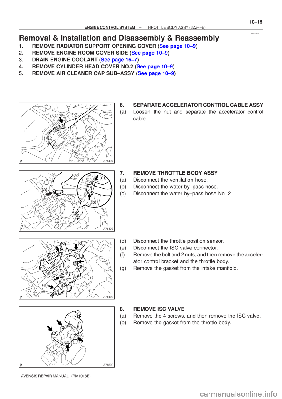
6. SEPARATE ACCELERATOR CONTROL CABLE ASSY
(a) Loosen the nut and separate the accelerator controlcable.
7. REMOVE THROTTLE BODY ASSY
(a) Disconnect the ventilation hose.
(b) Disconnect the water by±pass hose.
(c) Disconnect the water by±pass hose No. 2.
(d) Disconnect the throttle position sensor.
(e) Disconnect the ISC valve connector.
(f) Remove the bolt and 2 nuts, and then remove the acceler- ator control bracket and the throttle body.
(g) Remove the gasket from the intake manifold.
8. REMOVE ISC VALVE
(a) Remove the 4 screws, and then remove the ISC valve.
(b) Remove the gasket from the throttle body.
Page 1815 of 5135
100FA±01
A79596
A78436
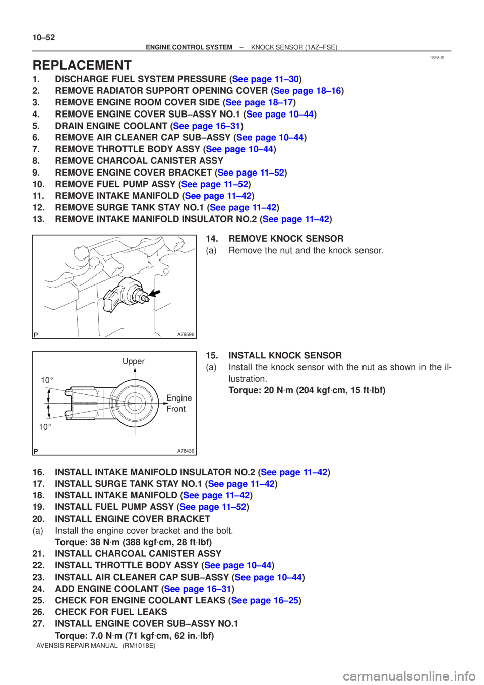
10�
10 � Upper
Engine
Front
10±52
±
ENGINE CONTROL SYSTEM KNOCK SENSOR(1AZ±FSE)
AVENSIS REPAIR MANUAL (RM1018E)
REPLACEMENT
1.DISCHARGE FUEL SYSTEM PRESSURE (See page 11±30)
2.REMOVE RADIATOR SUPPORT OPENING COVER (See page 18±16)
3.REMOVE ENGINE ROOM COVER SIDE (See page 18±17)
4.REMOVE ENGINE COVER SUB±ASSY NO.1 (See page 10±44)
5.DRAIN ENGINE COOLANT (See page 16±31)
6.REMOVE AIR CLEANER CAP SUB±ASSY (See page 10±44)
7.REMOVE THROTTLE BODY ASSY (See page 10±44)
8.REMOVE CHARCOAL CANISTER ASSY
9.REMOVE ENGINE COVER BRACKET (See page 11±52)
10.REMOVE FUEL PUMP ASSY (See page 11±52)
11.REMOVE INTAKE MANIFOLD (See page 11±42)
12.REMOVE SURGE TANK STAY NO.1 (See page 11±42)
13.REMOVE INTAKE MANIFOLD INSULATOR NO.2 (See page 11±42) 14.REMOVE KNOCK SENSOR
(a)Remove the nut and the knock sensor.
15.INSTALL KNOCK SENSOR
(a)Install the knock sensor with the nut as shown in the il-lustration.
Torque: 20 N �m (204 kgf �cm, 15 ft �lbf)
16.INSTALL INTAKE MANIFOLD INSULATOR NO.2 (See page 11±42)
17.INSTALL SURGE TANK STAY NO.1 (See page 11±42)
18.INSTALL INTAKE MANIFOLD (See page 11±42)
19.INSTALL FUEL PUMP ASSY (See page 11±52)
20. INSTALL ENGINE COVER BRACKET
(a) Install the engine cover bracket and the bolt. Torque: 38 N �m (388 kgf �cm, 28 ft �lbf)
21. INSTALL CHARCOAL CANISTER ASSY
22.INSTALL THROTTLE BODY ASSY (See page 10±44)
23.INSTALL AIR CLEANER CAP SUB±ASSY (See page 10±44)
24.ADD ENGINE COOLANT (See page 16±31)
25.CHECK FOR ENGINE COOLANT LEAKS (See page 16±25)
26. CHECK FOR FUEL LEAKS
27. INSTALL ENGINE COVER SUB±ASSY NO.1
Torque: 7.0 N �m (71 kgf �cm, 62 in. �lbf)
Page 1822 of 5135
100FJ±01
A78509
A81620
(a)(c)
(c)
(b)
(d)
(f)
(g)
(d)
(h)
Air Cleaner Clamp
A78510
10±44
±
ENGINE CONTROL SYSTEM THROTTLE BODY ASSY(1AZ±FSE)
AVENSIS REPAIR MANUAL (RM1018E)
REPLACEMENT
1.REMOVE ENGINE ROOM COVER SIDE (See page 10±26)
2.REMOVE RADIATOR SUPPORT OPENING COVER (See page 10±26)
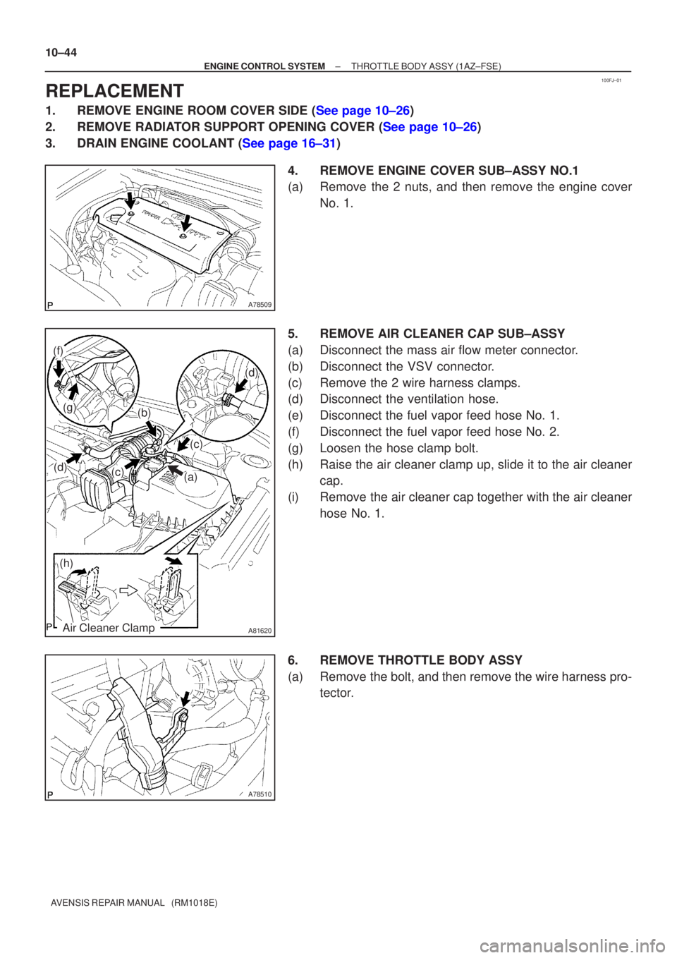
3.DRAIN ENGINE COOLANT (See page 16±31) 4. REMOVE ENGINE COVER SUB±ASSY NO.1
(a) Remove the 2 nuts, and then remove the engine coverNo. 1.
5. REMOVE AIR CLEANER CAP SUB±ASSY
(a) Disconnect the mass air flow meter connector.
(b) Disconnect the VSV connector.
(c) Remove the 2 wire harness clamps.
(d) Disconnect the ventilation hose.
(e) Disconnect the fuel vapor feed hose No. 1.
(f) Disconnect the fuel vapor feed hose No. 2.
(g) Loosen the hose clamp bolt.
(h) Raise the air cleaner clamp up, slide it to the air cleaner cap.
(i) Remove the air cleaner cap together with the air cleaner hose No. 1.
6. REMOVE THROTTLE BODY ASSY
(a) Remove the bolt, and then remove the wire harness pro- tector.
Page 1870 of 5135
110TD±01
A79578
A79579
A79580
11±42
±
FUEL FUEL INJECTOR ASSY (1AZ±FSE)
AVENSIS REPAIR MANUAL (RM1018E)
REPLACEMENT
1.DISCHARGE FUEL SYSTEM PRESSURE (See page 11±30)
2.REMOVE RADIATOR SUPPORT OPENING COVER (See page 18±16)
3.REMOVE ENGINE ROOM COVER SIDE (See page 18±17)
4.REMOVE ENGINE COVER SUB±ASSY NO.1 (See page 10±44)
5.DRAIN ENGINE COOLANT (See page 16±31)
6.REMOVE AIR CLEANER CAP SUB±ASSY (See page 10±44)
7.REMOVE THROTTLE BODY ASSY (See page 10±44)
8. REMOVE CHARCOAL CANISTER ASSY
9.REMOVE ENGINE COVER BRACKET (See page 11±52)
10.REMOVE FUEL PUMP ASSY(See page 11±52) 11. REMOVE INTAKE MANIFOLD
(a) Remove the ventilation hose No. 1.
(b) Disconnect the 2 vacuum hoses from the VSV.
(c) Disconnect the union to connector tube hose from thebrake booster assy.
(d) Remove the 5 bolts and 2 nuts from the intake manifold.
Page 1902 of 5135
110UD±01
A79188
A80091SST
A79190
11±82
± FUELFUEL FILTER ASSY (1CD±FTV)
AVENSIS REPAIR MANUAL (RM1018E)
FUEL FILTER ASSY (1CD±FTV)
REPLACEMENT
1. REMOVE AIR CLEANER ASSY
(a) Disconnect the connector.
(b) Remove the air cleaner cap with the air cleaner hose.
(c) Remove the air cleaner filter element.
(d) Remove the 3 bolts and the air cleaner case.
2. REMOVE FUEL FILTER ASSY
(a) Disconnect the 2 fuel hose from the fuel filter. (STD or COLD)
(b) Disconnect the 3 fuel hose from the fuel filter. (W/ ADDTIONAL HEATER)
(c) Disconnect the 2 connectors.
(d) Remove the 2 bolts and the fuel filter.
3. DRAIN FUEL
(a) Loosen the drain plug, and drain the fuel from the fuel filter.
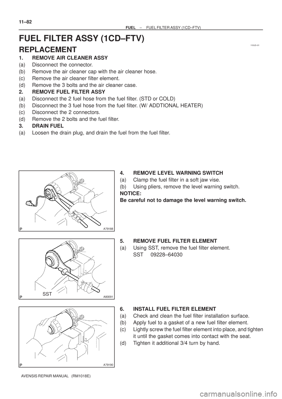
4. REMOVE LEVEL WARNING SWITCH
(a) Clamp the fuel filter in a soft jaw vise.
(b) Using pliers, remove the level warning switch.
NOTICE:
Be careful not to damage the level warning switch.
5. REMOVE FUEL FILTER ELEMENT
(a) Using SST, remove the fuel filter element.
SST 09228±64030
6. INSTALL FUEL FILTER ELEMENT
(a) Check and clean the fuel filter installation surface.
(b) Apply fuel to a gasket of a new fuel filter element.
(c) Lightly screw the fuel filter element into place, and tighten
it until the gasket comes into contact with the seat.
(d) Tighten it additional 3/4 turn by hand.
Page 1910 of 5135
110UA±01
A15950
±
FUEL INJECTION OR SUPPLY PUMP ASSY(1CD±FTV)
11±69
AVENSIS REPAIR MANUAL (RM1018E)
REPLACEMENT
1.REMOVE FRONT WHEEL RH
2.DRAIN ENGINE COOLANT(See page 16±44)
3.REMOVE ENGINE UNDER COVER SUB±ASSY NO.1
4.REMOVE ENGINE UNDER COVER RH
5.REMOVE RADIATOR SUPPORT OPENING COVER
6.REMOVE ENGINE ROOM COVER SIDE
7.REMOVE AIR CLEANER ASSY (See page 11±60)
8.REMOVE ENGINE COVER NO.1
(a)Remove the 5 nuts and the engine cover.
9.REMOVE RADIATOR RESERVE TANK ASSY(See page 16±50)
10.DISCONNECT RADIATOR HOSE OUTLET
(a)Disconnect the radiator hose outlet from the water inlet.
11.REMOVE V (COOLER COMPRESSOR TO CRANKSHAFT PULLEY) BELT NO.1
(See page 14±269)
12.REMOVE GENERATOR V BELT (See page 14±269)
13.REMOVE INJECTOR DRIVER
(a)Remove the 2 nuts which are used to secure the injector driver.
(b)Disconnect the injector driver connector and the harness clamp.
(c)Remove the injector driver.
14.REMOVE ENGINE MOUNTING INSULATOR SUB±ASSY RH(See page 14±307)
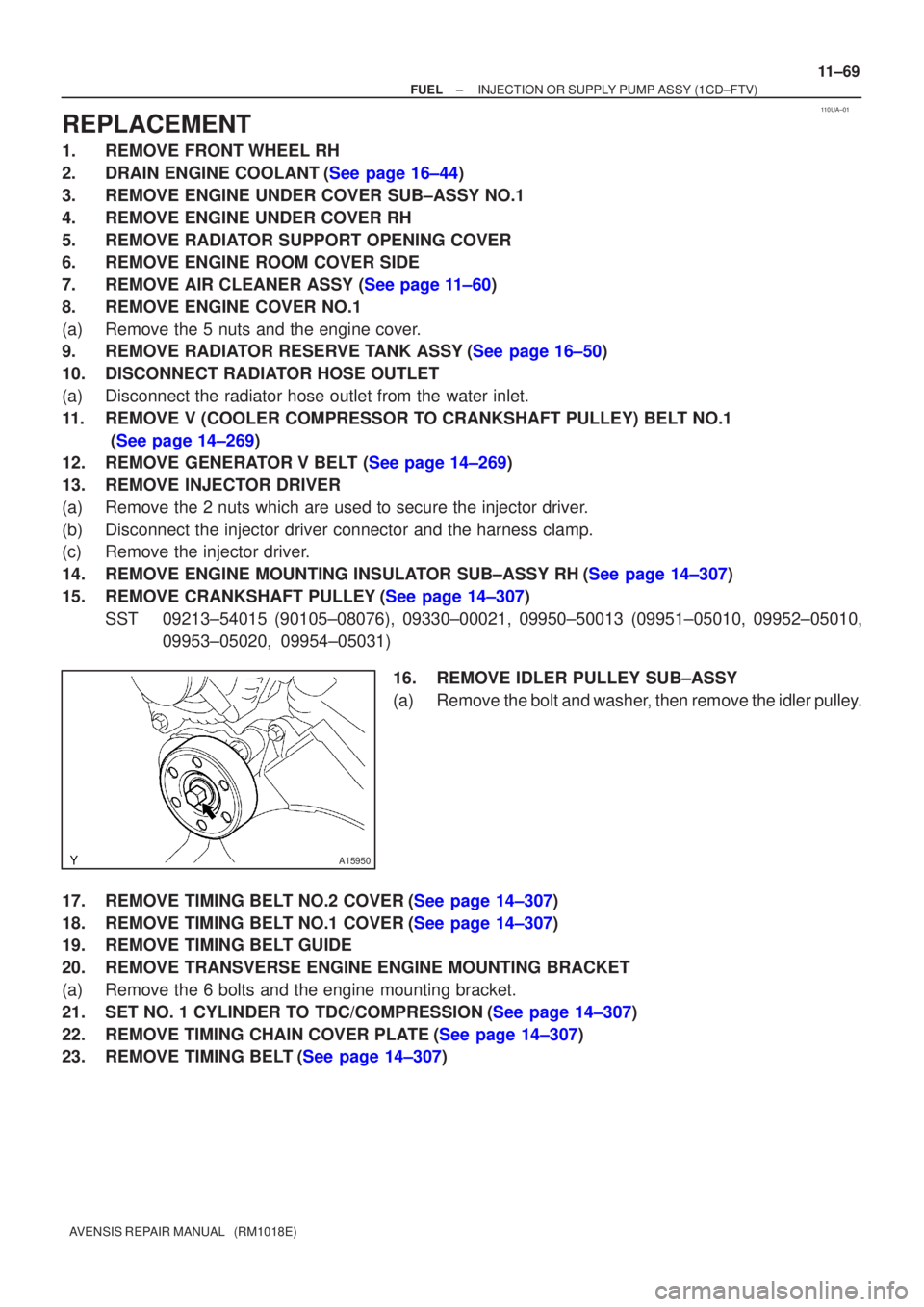
15.REMOVE CRANKSHAFT PULLEY(See page 14±307)
SST09213±54015 (90105±08076), 09330±00021, 09950±50013 (0995\
1±05010, 09952±05010, 09953±05020, 09954±05031)
16.REMOVE IDLER PULLEY SUB±ASSY
(a)Remove the bolt and washer, then remove the idler pulley.
17.REMOVE TIMING BELT NO.2 COVER(See page 14±307)
18.REMOVE TIMING BELT NO.1 COVER(See page 14±307)
19. REMOVE TIMING BELT GUIDE
20. REMOVE TRANSVERSE ENGINE ENGINE MOUNTING BRACKET
(a) Remove the 6 bolts and the engine mounting bracket.
21.SET NO. 1 CYLINDER TO TDC/COMPRESSION(See page 14±307)
22.REMOVE TIMING CHAIN COVER PLATE(See page 14±307)
23.REMOVE TIMING BELT(See page 14±307)
Page 1951 of 5135
A63026
A60576
Fuel Tube
Connector Clip
Nylon Tube
O±ring Pipe
A62989
SST
A77883
±
FUEL FUEL TANK ASSY(DIESEL)
11±105
AVENSIS REPAIR MANUAL (RM1018E)
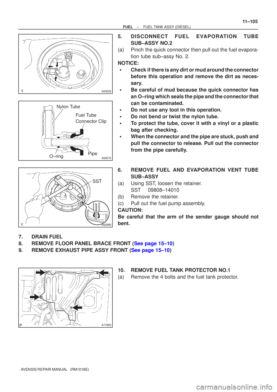
5.DISCONNECT FUEL EVAPOR ATION TUBE
SUB±ASSY NO.2
(a)Pinch the quick connector then pull out the fuel evapora-
tion tube sub±assy No. 2.
NOTICE:
�Check if there is any dirt or mud around the connector
before this operation and remove the dirt as neces-
sary.
�Be careful of mud because the quick connector has
an O±ring which seals the pipe and the connector that
can be contaminated.
�Do not use any tool in this operation.
�Do not bend or twist the nylon tube.
�To protect the tube, cover it with a vinyl or a plastic
bag after checking.
�When the connector and the pipe are stuck, push and
pull the connector to release. Pull out the connector
from the pipe carefully.
6.REMOVE FUEL AND EVAPORATION VENT TUBE SUB±ASSY
(a)Using SST, loosen the retainer. SST09808±14010
(b)Remove the retainer.
(c)Pull out the fuel pump assembly.
CAUTION:
Be careful that the arm of the sender gauge should not
bent.
7.DRAIN FUEL
8.REMOVE FLOOR PANEL BRACE FRONT (See page 15±10)
9.REMOVE EXHAUST PIPE ASSY FRONT (See page 15±10)
10. REMOVE FUEL TANK PROTECTOR NO.1
(a) Remove the 4 bolts and the fuel tank protector.