Page 4768 of 5135
4018A−01
D31327
D31328
D31328
D31327
40 −26
−
AUTOMATIC TRANSMISSION / TRANS TRANSMISSION OIL COOLER (U151E)
AVENSIS Supplement (RM1045E)
TRANSMISSION OIL COOLER (U 151E)
REPLACEMENT
1. DRAIN AUTOMATIC TRANSAXLE FLUID (SEE PUB. NO. RM 1018E, PAGE 40 −2)
2. DRAIN COOLANT (SEE PAGE 16− 7)
3. REMOVE TRANSMISSION OIL COOLER
(a) Loosen the clips and disconnect the 4 hoses from the transmission oil cooler.
(b) Remove the 3 bolts and the oil cooler from the bracket.
4. INSTALL TRANSMISSION OIL COOLER
(a) Install the oil cooler to the bracket with the 3 bolts. Torque: 12N �m( 122 kgf �cm, 9 ft �lbf)
(b) Connect the 4 hoses with the clips to the transmission.
Page 4772 of 5135

40188−01
C91925
D30865
AT0103
C91927
− AUTOMATIC TRANSMISSION / TRANSTRANSMISSION VALVE BODY ASSY (U151E)
40−19
AVENSIS Supplement (RM1045E)
TRANSMISSION VALVE BODY ASSY (U151E)
REPLACEMENT
1. REMOVE ENGINE UNDER COVER LH
2. DRAIN AUTOMATIC TRANSAXLE FLUID
(a) Remove the drain plug and gasket, and drain ATF.
(b) Install a new gasket and the drain plug.
Torque: 47 N�m (479 kgf�cm, 35 ft�lbf)
3. REMOVE AUTOMATIC TRANSAXLE OIL PAN
SUB−ASSY
(a) Remove the 18 bolts, oil pan and gasket.
NOTICE:
Some fluid will remain in the oil pan. Remove all of the oil
pan bolts, and carefully remove the oil pan assembly.
(b) Remove the 2 magnets from the oil pan.
(c) Examine the particles in the oil pan.
(1) Collect any steel chips with the removed magnets.
Look at the chips and particles in the pan and on the
magnets carefully to see the type of wear which
might be found in the transaxle.
Steel (magnetic): bearing, gear and plate wear
Brass (non−magnetic): bearing wear
4. DISCONNECT TRANSMISSION WIRE
(a) Disconnect the 7 shift solenoid valve connectors.
(b) Remove the bolt and lock plate, and disconnect the ATF
temperature sensor.
Page 4777 of 5135

40187−01
C91925
D30865
AT0103
C91927
40−16
− AUTOMATIC TRANSMISSION / TRANSTRANSMISSION WIRE (U151E)
AVENSIS Supplement (RM1045E)
TRANSMISSION WIRE (U151E)
REPLACEMENT
1. REMOVE ENGINE UNDER COVER LH
2. DRAIN AUTOMATIC TRANSAXLE FLUID
(a) Remove the drain plug and gasket, and drain ATF.
(b) Install a new gasket and the drain plug.
Torque: 47 N�m (479 kgf�cm, 35 ft�lbf)
3. REMOVE AUTOMATIC TRANSAXLE OIL PAN
SUB−ASSY
(a) Remove the 18 bolts, oil pan and gasket.
NOTICE:
Some fluid will remain in the oil pan. Remove all of the oil
pan bolts, and carefully remove the oil pan assembly.
(b) Remove the 2 magnets from the oil pan.
(c) Examine the particles in the oil pan.
(1) Collect any steel chips with the removed magnets.
Look at the chips and particles in the pan and on the
magnets carefully to see the type of wear which
might be found in the transaxle.
Steel (magnetic): bearing, gear and plate wear
Brass (non−magnetic): bearing wear
4. DISCONNECT TRANSMISSION WIRE
(a) Disconnect the 7 shift solenoid valve connectors.
(b) Remove the bolt and lock plate, and disconnect the ATF
temperature sensor.
Page 5051 of 5135

141UL–01
A93669
A60622
14–32–
ENGINE MECHANICAL CYLINDER HEAD GASKET (1ZZ–FE/3ZZ–FE)(From
February, 2004)
AVENSIS REPAIR MANUAL SUPPLEMENT
(RM1098E)
REPLACEMENT
1. DISCHARGE FUEL SYSTEM PRESSURE (See Pub. No. RM1018E on page 11–1)
2. REMOVE RADIATOR SUPPORT OPENING COVER (See page 14–9)
3. REMOVE ENGINE ROOM COVER SIDE (See page 14–9)
4. REMOVE FRONT WHEEL RH
5. REMOVE ENGINE UNDER COVER SUB–ASSY NO.1 (See page 14–9)
6. REMOVE ENGINE UNDER COVER RH (See page 14–9)
7. DRAIN ENGINE COOLANT (See page 16–5)
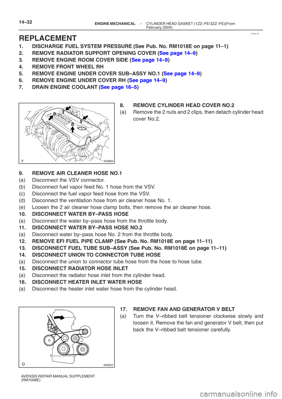
8. REMOVE CYLINDER HEAD COVER NO.2
(a) Remove the 2 nuts and 2 clips, then detach cylinder headcover No.2.
9. REMOVE AIR CLEANER HOSE NO.1
(a) Disconnect the VSV connector.
(b) Disconnect fuel vapor feed No. 1 hose from the VSV.
(c) Disconnect the fuel vapor feed hose from the VSV.
(d) Disconnect the ventilation hose from air cleaner hose No. 1.
(e) Loosen the 2 air cleaner hose clamp bolts, then remove the air cleaner h\
ose.
10. DISCONNECT WATER BY–PASS HOSE
(a) Disconnect the water by–pass hose from the throttle body.
11. DISCONNECT WATER BY–PASS HOSE NO.2
(a) Disconnect water by–pass hose No. 2 from the throttle body.
12. REMOVE EFI FUEL PIPE CLAMP (See Pub. No. RM1018E on page 11–11)
13. DISCONNECT FUEL TUBE SUB–ASSY (See Pub. No. RM1018E on page 11–11)
14. DISCONNECT UNION TO CONNECTOR TUBE HOSE
(a) Disconnect the union to connector tube hose from the hose to hose tube.
15. DISCONNECT RADIATOR HOSE INLET
(a) Disconnect the radiator hose inlet from the cylinder head.
16. DISCONNECT HEATER INLET WATER HOSE
(a) Disconnect the heater inlet water hose from the cylinder head. 17. REMOVE FAN AND GENERATOR V BELT
(a) Turn the V–ribbed belt tensioner clockwise slowly andloosen it. Remove the fan and generator V belt, then put
back the V–ribbed belt tensioner carefully.
Page 5067 of 5135

A78516
A93669
14–10–
ENGINE MECHANICAL PARTIAL ENGINE ASSY (1ZZ–FE/3ZZ–FE)(From
February, 2004)
AVENSIS REPAIR MANUAL SUPPLEMENT
(RM1098E)
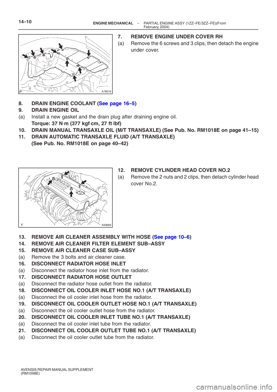
7. REMOVE ENGINE UNDER COVER RH
(a) Remove the 6 screws and 3 clips, then detach the engine under cover.
8. DRAIN ENGINE COOLANT (See page 16–5)
9. DRAIN ENGINE OIL
(a) Install a new gasket and the drain plug after draining engine oil.
Torque: 37 N ⋅m (377 kgf ⋅cm, 27 ft ⋅lbf)
10. DRAIN MANUAL TRANSAXLE OIL (M/T TRANSAXLE) (See Pub. No. RM1018E on p\
age 41–15)
11. DRAIN AUTOMATIC TRANSAXLE FLUID (A/T TRANSAXLE)
(See Pub. No. RM1018E on page 40–42)
12. REMOVE CYLINDER HEAD COVER NO.2
(a) Remove the 2 nuts and 2 clips, then detach cylinder head
cover No.2.
13. REMOVE AIR CLEANER ASSEMBLY WITH HOSE (See page 10–6)
14. REMOVE AIR CLEANER FILTER ELEMENT SUB–ASSY
15. REMOVE AIR CLEANER CASE SUB–ASSY
(a) Remove the 3 bolts and air cleaner case.
16. DISCONNECT RADIATOR HOSE INLET
(a) Disconnect the radiator hose inlet from the radiator.
17. DISCONNECT RADIATOR HOSE OUTLET
(a) Disconnect the radiator hose outlet from the radiator.
18. DISCONNECT OIL COOLER INLET HOSE NO.1 (A/T TRANSAXLE)
(a) Disconnect the oil cooler inlet hose from the radiator.
19. DISCONNECT OIL COOLER OUTLET HOSE NO.1 (A/T TRANSAXLE)
(a) Disconnect the oil cooler outlet hose from the radiator.
20. DISCONNECT OIL COOLER INLET TUBE NO.1 (A/T TRANSAXLE)
(a) Disconnect the oil cooler inlet tube from the radiator.
21. DISCONNECT OIL COOLER OUTLET TUBE NO.1 (A/T TRANSAXLE)
(a) Disconnect the oil cooler outlet tube from the radiator.
Page 5132 of 5135

A62813
Front Mark
Piston Ring
Compressor
A65713
Front Mark
A65714
SST
A65715
Paint Mark90� Engine
Front
A64845
14–76
– ENGINE MECHANICALCYLINDER BLOCK ASSY (1ZZ–FE/3ZZ–FE)
1ZZ–FE,3ZZ–FE ENGINE REPAIR MANUAL
(RM1099E)
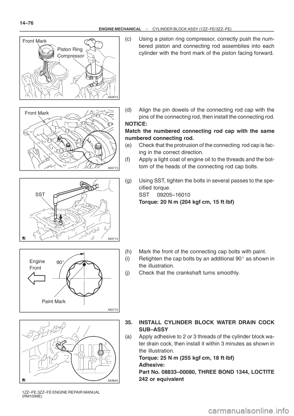
(c) Using a piston ring compressor, correctly push the num-
bered piston and connecting rod assemblies into each
cylinder with the front mark of the piston facing forward.
(d) Align the pin dowels of the connecting rod cap with the
pins of the connecting rod, then install the connecting rod.
NOTICE:
Match the numbered connecting rod cap with the same
numbered connecting rod.
(e) Check that the protrusion of the connecting rod cap is fac-
ing in the correct direction.
(f) Apply a light coat of engine oil to the threads and the bot-
tom of the heads of the connecting rod cap bolts.
(g) Using SST, tighten the bolts in several passes to the spe-
cified torque.
SST 09205–16010
Torque: 20 N⋅m (204 kgf⋅cm, 15 ft⋅lbf)
(h) Mark the front of the connecting cap bolts with paint.
(i) Retighten the cap bolts by an additional 90� as shown in
the illustration.
(j) Check that the crankshaft turns smoothly.
35. INSTALL CYLINDER BLOCK WATER DRAIN COCK
SUB–ASSY
(a) Apply adhesive to 2 or 3 threads of the cylinder block wa-
ter drain cock, then install it within 3 minutes as shown in
the illustration.
Torque: 25 N⋅m (255 kgf⋅cm, 18 ft⋅lbf)
Adhesive:
Part No. 08833–00080, THREE BOND 1344, LOCTITE
242 or equivalent