Page 4566 of 5135
(From September,
2003)11 −67
AVENSIS Supplement (RM1045E)
REPLACEMENT
1. DRAIN ENGINE COOLANT (See page 16 −19)
2. REMOVE RAD")
110UC−02
A93407SST
A93406
SST
−
FUEL COMMON RAIL ASSY (1CD −FTV)(From September,
2003)11 −67
AVENSIS Supplement (RM1045E)
REPLACEMENT
1. DRAIN ENGINE COOLANT (See page 16 −19)
2. REMOVE RADIATOR SUPPORT OPENING COVER
3. REMOVE ENGINE COVER SUB −ASSY NO.1
(a) Remove the 5 nuts and engine cover.
4. REMOVE RADIATOR RESERVE TANK SUB −ASSY (See Pub.No. RM1018E on page 16 −50)
5. REMOVE FUEL INLET PIPE SUB −ASSY
NOTICE:
After removing the fuel inlet pipe, cover the common rail
and injection pump with vinyl tape to prevent dust from be-
ing introduced.
(a) Using SST, remove the fuel inlet pipe from the common rail.
SST 09023 −12700
(b) Using SST, remove the fuel inlet pipe from the injection
pump.
SST 09023 −12700
6. REMOVE FUEL PIPE NO.3 (See page 11 −46)
SST 09023 −12700
7. REMOVE INJECTION PIPE SUB −ASSY NO.1
(a) Remove the 2 nuts and 2 upper injection pipe clamps from the intake manifold.
(b) Using SST, remove the injection pipe from the common rail side.
SST 09023 −12700
(c) Using SST, remove the injection pipe from the injector side.
SST 09023 −12700
(d) After removing the fuel pipe, to prevent dust or foreign ob-
jects from being introduced, cover the common rail with
vinyl tape and protect the injector inlet with a vinyl or plas-
tic bag.
8. REMOVE INJECTION PIPE SUB −ASSY NO.2
SST 09023 −12700
HINT:
Perform the same procedures as the injection pipe No. 1.
9. REMOVE INJECTION PIPE SUB −ASSY NO.3
SST 09023 −12700
HINT:
Perform the same procedures as the injection pipe No. 1.
Page 4569 of 5135

SST
11−70−
FUEL COMMON RAIL ASSY (1CD −FTV)(From September,
2003)
AVENSIS Supplement (RM1045E)
21. INSTALL FUEL INLET PIPE SUB −ASSY
NOTICE:
S In case of replacing th")
A87960
30 cm
(11.81 in.)
SST
11−70−
FUEL COMMON RAIL ASSY (1CD −FTV)(From September,
2003)
AVENSIS Supplement (RM1045E)
21. INSTALL FUEL INLET PIPE SUB −ASSY
NOTICE:
S In case of replacing the common rail, the fuel inlet
pipe must be replaced, too.
S When assembling the pipe, perform the operation
with the engine cold under room temperature.
(a) Temporarily install the fuel inlet pipe.
(b) Using SST, tighten the nut of the fuel inlet pipe to the com-
mon rail side.
SST 09023 −12700
Torque:
31 N �m (316 kgf �cm, 23 ft �lbf) with SST
34 N �m (347 kgf �cm, 25 ft �lbf) without SST
HINT:
S Use a torque wrench with the fulcrum length of 30 cm
(11.81 in.).
S After the inlet pipe is reassembled, check that the used
pipe has no deflection and is installed properly. If it has
deflection or could not be installed properly, replace the
used pipe with a new pipe.
(c) Using SST, tighten the nut of the fuel inlet pipe to the injec- tion pump side.
SST 09023 −12700
Torque:
31 N �m (316 kgf �cm, 23 ft �lbf) with SST
34 N �m (347 kgf �cm, 25 ft �lbf) without SST
HINT:
S Use a torque wrench with the fulcrum length of 30 cm
(11.81 in.).
S After the inlet pipe is reassembled, check that the used
pipe has no deflection and is installed properly. If it has
deflection or could not be installed properly, replace the
used pipe with a new pipe.
22. INSTALL RADIATOR RESERVE TANK SUB −ASSY (See Pub. No. RM1018E on page 16 −50)
23. INSTALL ENGINE COVER SUB −ASSY NO.1
Torque: 8.0 N �m (82 kgf �cm, 71 in. �lbf)
24. ADD ENGINE COOLANT (See page 16 −19)
25. CHECK FOR ENGINE COOLANT LEAKS (See page 16 −15)
26. CHECK FOR FUEL LEAKS (See page 11 −46)
Page 4570 of 5135
110UB−02
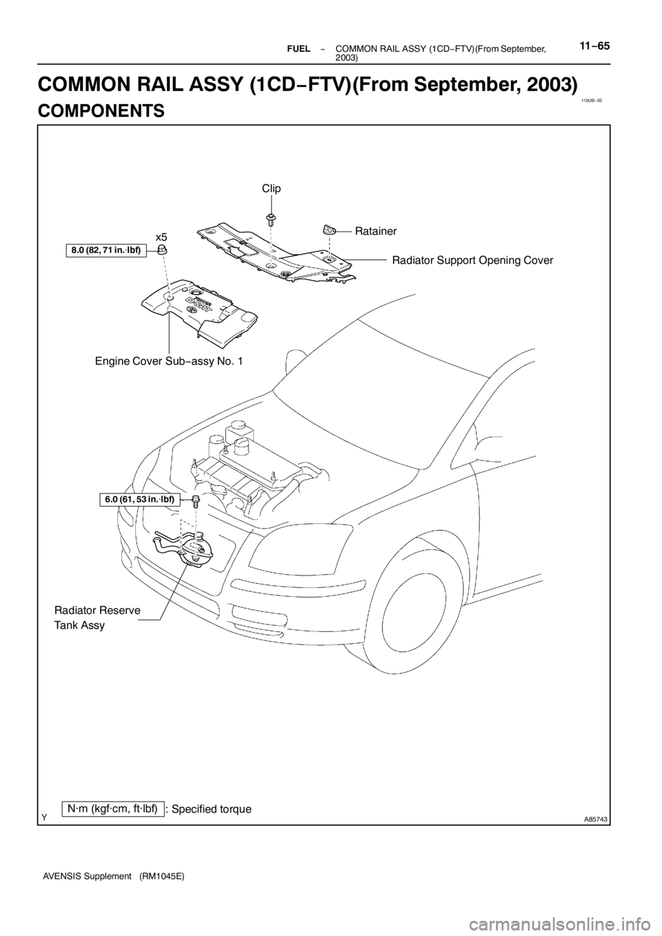
A85743
8.0 (82, 71 in.�lbf)
Engine Cover Sub−assy No. 1Radiator Support Opening Cover
N·m (kgf·cm, ft·lbf)
: Specified torque
6.0 (61, 53 in.�lbf)
Radiator Reserve
Tank Assy
Clip
Ratainer
x5
− FUELCOMMON RAIL ASSY (1CD−FTV)(From September,
2003)11−65
AVENSIS Supplement (RM1045E)
COMMON RAIL ASSY (1CD−FTV)(From September, 2003)
COMPONENTS
Page 4572 of 5135
110U9−02
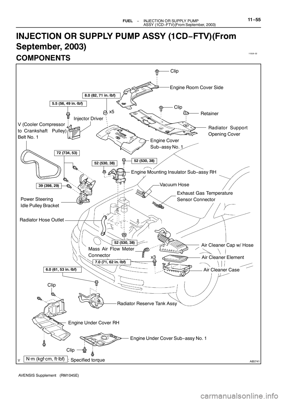
A85741
Air Cleaner Cap w/ Hose
Air Cleaner Element
Air Cleaner Case
7.0 (71, 62 in.�lbf)
N·m (kgf·cm, ft·lbf)
: Specified torque
Radiator Hose Outlet
Clip
Engine Room Cover Side
Clip
Retainer
Radiator Support
Opening Cover
8.0 (82, 71 in.�lbf)
5.5 (56, 49 in.�lbf)
V (Cooler Compressor
to Crankshaft Pulley)
Belt No. 1
Injector Driver
72 (734, 53)
52 (530, 38)52 (530, 38)
Engine Cover
Sub−assy No. 1
Engine Mounting Insulator Sub−assy RH
39 (398, 29)
Power Steering
Idle Pulley Bracket
52 (530, 38)
Clip
Engine Under Cover RH
Engine Under Cover Sub−assy No. 1
Clip
Radiator Reserve Tank Assy
6.0 (61, 53 in.�lbf)
x5
x3
Exhaust Gas Temperature
Sensor Connector
Vacuum Hose
Mass Air Flow Meter
Connector
− FUELINJECTION OR SUPPLY PUMP
ASSY (1CD−FTV)(From September, 2003)11−55
AVENSIS Supplement (RM1045E)
INJECTION OR SUPPLY PUMP ASSY (1CD−FTV)(From
September, 2003)
COMPONENTS
Page 4575 of 5135

(a)
(b)(b)
(a)
(a)
A85630
11−46
− FUELINJECTOR ASSY (1CD−FTV)(From September, 2003)
AVENSIS Supplement (RM1045E)
REPLACEMENT
NOTICE:
If an incorrect injector compensation")
1111 D−01
A93661
(a)
(a)
(b)(b)
(a)
(a)
A85630
11−46
− FUELINJECTOR ASSY (1CD−FTV)(From September, 2003)
AVENSIS Supplement (RM1045E)
REPLACEMENT
NOTICE:
If an incorrect injector compensation code was registered with the ECM, it may rattle the engine as-
sembly or the engine idling may become rough. In addition, it may become a cause of engine failure
or shorten the life of the engine.
HINT:
SIn order to optimize the injector’s fuel injection characteristic, the ECM compensates the injection dura-
tion by each cylinder. The ECM stores and uses compensating data in the form of a 30−digit−alphanu-
meric value that is imprinted on the head portion of each injector as the injector compensation code.
SIf you installed a new injector, its own injector compensation code is needed to register with the ECM.
Also, if you replaced the ECM, the compensation codes of all the injectors are needed to register be-
cause the new ECM does not have the codes until they are registered.
SOnce the ECM is replaced, DTC P1601 will be present when turning the ignition switch to ON. This
is to inform you that the injector compensation codes are required to register with the ECM. In order
to clear the DTC, register the compensation codes first, then turn the ignition switch to OFF and wait
for 30 seconds or longer.
1. REMOVE VACUUM RESERVOIR SUB−ASSY
(a) Disconnect the 2 vacuum hoses and connector.
(b) Remove the 2 bolts and vacuum reservoir.
2. REMOVE RADIATOR SUPPORT OPENING COVER
3. REMOVE ENGINE COVER SUB−ASSY NO.1
(a) Remove the 5 nuts and engine cover.
4. REMOVE AIR CLEANER ASSY
(a) Disconnect the connector.
(b) Remove the air cleaner cap together with the air cleaner hose.
(c) Remove the air cleaner filter element.
(d) Remove the 3 bolts and air cleaner case.
5. REMOVE AIR TUBE NO.1
(a) Remove the 3 bolts and nut, then separate the air tube
No. 1.
(b) Loosen the hose clamp bolts.
6. REMOVE FUEL PIPE NO.3
(a) Remove the fuel pipe insulator.
Page 4584 of 5135
110U7−02
A85739
Radiator Support Opening Cover
Engine Cover Sub−assy No. 1
Vacuum Reservoir Sub−assy
Union to Connector Tube Hose
Air Cleaner Cap w/ Hose
Air Cleaner Element
Air Cleaner Case
N·m (kgf·cm, ft·lbf)
: Specified torque
8.0 (82, 71 in.�lbf)
8.3 (85, 73 in.�lbf)
7.0 (71, 62 in.�lbf)
Clip
Retainer
25 (255, 18)
Air Tube No. 1
25 (255, 18)
x5
x2
x3
25 (255, 18)
Mass Air Flow Meter
Connector
6.0 (61, 53 in.�lbf)
6.0 (61, 53 in.�lbf)
11−44
− FUELINJECTOR ASSY (1CD−FTV)(From September, 2003)
AVENSIS Supplement (RM1045E)
INJECTOR ASSY (1CD−FTV)(From September, 2003)
COMPONENTS
Page 4587 of 5135
1111 5−01
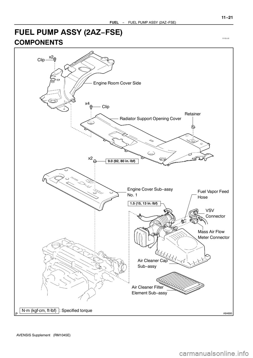
A84695
Mass Air Flow
Meter Connector
N·m (kgf·cm, ft·lbf) : Specified torqueEngine Cover Sub−assy
No. 1
9.0 (92, 80 in.�lbf)
VSV
Connector Fuel Vapor Feed
Hose
Clip
Engine Room Cover Side
Radiator Support Opening Cover
Clip
Retainer
x2
x4
1.5 (15, 13 in.�lbf)
Air Cleaner Filter
Element Sub−assy x2
Air Cleaner Cap
Sub−assy
− FUELFUEL PUMP ASSY (2AZ−FSE)
11−21
AVENSIS Supplement (RM1045E)
FUEL PUMP ASSY (2AZ−FSE)
COMPONENTS
Page 4590 of 5135

(b)
Pull Out
A88252
(a)
(b)
(c)
(d)
A77920
RHD:
LHD:
−
FUEL FUEL INJECTOR ASSY (2AZ −FSE)
11 −13
AVENSIS Supplement (RM1045E)
REPLACEMENT
1. DISCHARGE FUEL SYSTEM PRESSURE")
1111 4−01
A88253
(a)
(b)
Pull Out
A88252
(a)
(b)
(c)
(d)
A77920
RHD:
LHD:
−
FUEL FUEL INJECTOR ASSY (2AZ −FSE)
11 −13
AVENSIS Supplement (RM1045E)
REPLACEMENT
1. DISCHARGE FUEL SYSTEM PRESSURE (See page 11 −1)
2. REMOVE RADIATOR SUPPORT OPENING COVER (See page 10 −8)
3. REMOVE ENGINE ROOM COVER SIDE (See page 10 −8)
4. DISCONNECT ENGINE WIRE NO.3 (BATTERY NEGATIVE TERMINAL)
5. DRAIN ENGINE COOLANT (See page 16 −7)
6. REMOVE ENGINE COVER SUB −ASSY NO.1 (See page 10 −8)
7. REMOVE AIR CLEANER CAP SUB −ASSY (See page 10 −8)
8. REMOVE THROTTLE BODY ASSY (See page 10 −8)
9. REMOVE FUEL TUBE SUB −ASSY (See page 11 −24)
SST 09617 −24011
10. REMOVE FUEL HOSE (See page 11 −24)
11. REMOVE FUEL PIPE SUB −ASSY NO.1 (See page 11 −24)
SST 09023 −12900
12. REMOVE FUEL PUMP ASSY (See page 11 −24)
13. REMOVE CHARCOAL CANISTER ASSY
(a) Disconnect the fuel hose from the charcoal canister hose.
(b) Disconnect the charcoal canister outlet hose No. 1 from the charcoal canister.
(c) Pull out the charcoal canister from the charcoal canister base bracket.
14. REMOVE VACUUM SENSOR ASSY (LHD STEERING POSITION TYPE)
(a) Remove the wiring harness clamp.
(b) Disconnect the vacuum sensor connector.
(c) Disconnect the vacuum hose from the vacuum sensor.
(d) Remove the bolt, then remove the vacuum sensor.
15. REMOVE INTAKE MANIFOLD
(a) Disconnect the union to connector tube hose from the
brake booster.