Page 4759 of 5135

160MR−02
B12054
SST
B12052
B12053
Pry
PryPry
16
−12
−
COOLING WATER PUMP ASSY (2AZ −FSE)
AVENSIS Supplement (RM1045E)
WATER PUMP ASSY (2AZ −FSE)
REPLACEMENT
1. DRAIN COOLANT (See page 16 −7)
2. REMOVE RADIATOR SUPPORT OPENING COVER (See page 14 −23)
3. REMOVE ENGINE ROOM COVER SIDE (See page 14 −23)
4. REMOVE ENGINE UNDER COVER LH (See page 14 −23)
5. REMOVE ENGINE UNDER COVER NO.4 RH (See page 14 −23)
6. REMOVE ENGINE UNDER COVER RH (See page 14 −23)
7. REMOVE FAN AND GENERATOR V BELT (See page 14 −5)
SST 09249 −63010
8. REMOVE GENERATOR ASSY (See page 19 −8)
9. REMOVE WATER PUMP PULLEY
(a) Using SST, remove the 4 bolts and pump pulley. SST 09960 −10010 (09962 −01000, 09963 −00700)
(b) Disconnect the crankshaft position sensor wire clamp
from the water pump.
(c) Disconnect the crankshaft position sensor wire from the clamp on the water pump.
10. REMOVE WATER PUMP ASSY
(a) Remove the 4 bolts, 2 nuts, wire clamp and water pump.
(b) Using a screwdriver, pry out between the water pump and cylinder block, and remove the water pump.
NOTICE:
Be careful not to damage the contact surface of the water
pump and cylinder block.
Page 4762 of 5135
141NN−01
A61184
A85928
−
ENGINE MECHANICAL CRANKSHAFT SEAL (1CD−FTV)(From September,
2003)14 −177
AVENSIS Supplement (RM1045E)
CRANKSHAFT SEAL (1CD −FTV)(From September, 2003)
REPLACEMENT
1. DRAIN ENGINE OIL
(a) Install a new gasket and the drain plug after draining engine oil.
Torque: 34 N �m (350 kgf �cm, 25 ft �lbf)
2. REMOVE FRONT WHEEL RH
3. REMOVE ENGINE UNDER COVER SUB −ASSY NO.1
4. REMOVE ENGINE UNDER COVER RH
5. REMOVE RADIATOR SUPPORT OPENING COVER
6. REMOVE ENGINE ROOM COVER SIDE
7. REMOVE ENGINE COVER NO.1 (See page 14 −90)
8. REMOVE INJECTOR DRIVER (See page 14 −108)
9. REMOVE V (COOLER COMPRESSOR TO CRANKSHAFT PULLEY) BELT NO.1
(See Pub. No. RM1018E on page 14 −269)
10. REMOVE GENERATOR V BELT (See Pub. No. RM1018E on page 14 −269)
11. SEPARATE POWER STEERING IDLE PULLEY BRACKET (See page 14 −138)
12. DISCONNECT ENGINE WIRE (See page 14 −138)
13. DISCONNECT VACUUM HOSE (See page 14 −108)
14. REM O VE ENG I NE M O UNTI NG I NSULATO R SUB−ASSY RH
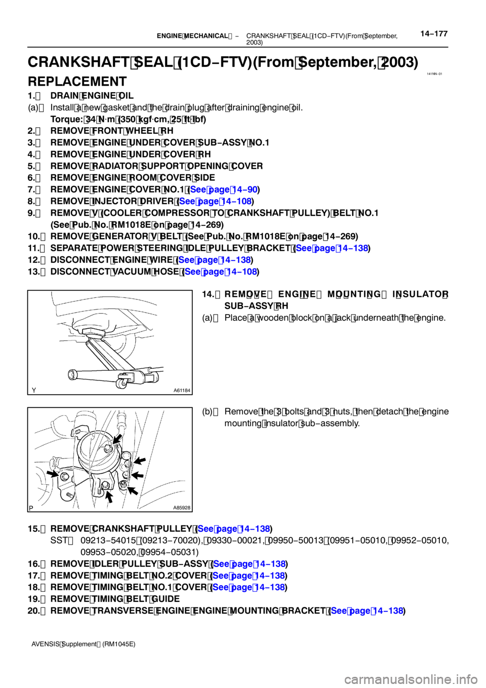
(a) Place a wooden block on a jack underneath the engine.
(b) Remove the 3 bolts and 3 nuts, then detach the engine mounting insulator sub −assembly.
15. REMOVE CRANKSHAFT PULLEY (See page 14 −138)
SST 09213 −54015 (09213 −70020), 09330 −00021, 09950 −50013 (09951 −05010, 09952 −05010,
09953 −05020, 09954 −05031)
16. REMOVE IDLER PULLEY SUB −ASSY (See page 14 −138)
17. REMOVE TIMING BELT NO.2 COVER (See page 14 −138)
18. REMOVE TIMING BELT NO.1 COVER (See page 14 −138)
19. REMOVE TIMING BELT GUIDE
20. REMOVE TRANSVERSE ENGINE ENGINE MOUNTING BRACKET (See page 14 −138)
Page 4765 of 5135
551AN−01
I35326
I35327
I35328
55 −4
−
HEATER & AIR CONDITIONER W/PULLEY COMPRESSOR ASSY (2AZ −FSE)
AVENSIS Supplement (RM1045E)
REPLACEMENT
1 . DISCHARGE REFRIGERANT FROM REFRIGERATION SYSTEM
(See Pub. No. RM 1018E, page 55 −38)
SST 07110 −58060 ( 07117 −58080, 07117 −58090, 07117 −78050, 07117 −88060, 07117 −88070,
07117 −88080)
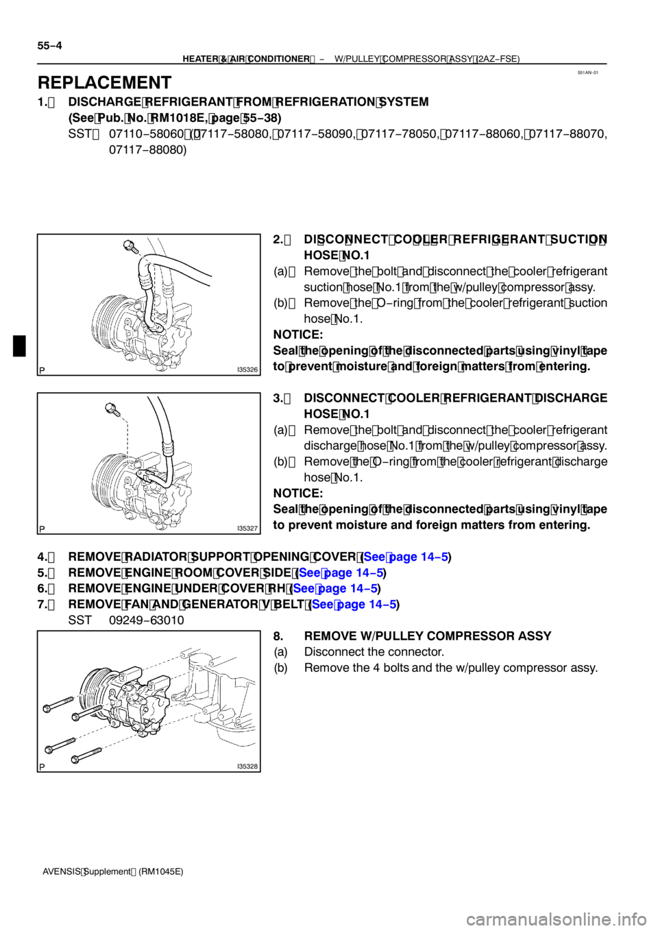
2. DI SCO NNECT CO O L ER REFRI G ERANT SUCTI O NHOSE NO. 1
(a) Remove the bolt and disconnect the cooler refrigerant
suction hose No.1 from the w/pulley compressor assy.
(b) Remove the O −ring from the cooler refrigerant suction
hose No.1.
NOTICE:
Seal the opening of the disconnected parts using vinyl tape
to prevent moisture and foreign matters from entering.
3. DISCONNECT COOLER REFRIGERANT DISCHARGE HOSE NO. 1
(a) Remove the bolt and disconnect the cooler refrigerant discharge hose No.1 from the w/pulley compressor assy.
(b) Remove the O −ring from the cooler refrigerant discharge
hose No.1.
NOTICE:
Seal the opening of the disconnected parts using vinyl tape
to prevent moisture and foreign matters from entering.
4. REMOVE RADIATOR SUPPORT OPENING COVER (See page 14− 5)
5. REMOVE ENGINE ROOM COVER SIDE (See page 14− 5)
6. REMOVE ENGINE UNDER COVER RH (See page 14− 5)
7. REMOVE FAN AND GENERATOR V BELT (See page 14− 5)
SST 09249 −63010
8. REMOVE W/PULLEY COMPRESSOR ASSY
(a) Disconnect the connector.
(b) Remove the 4 bolts and the w/pulley compressor assy.
Page 5051 of 5135
141UL–01
A93669
A60622
14–32–
ENGINE MECHANICAL CYLINDER HEAD GASKET (1ZZ–FE/3ZZ–FE)(From
February, 2004)
AVENSIS REPAIR MANUAL SUPPLEMENT
(RM1098E)
REPLACEMENT
1. DISCHARGE FUEL SYSTEM PRESSURE (See Pub. No. RM1018E on page 11–1)
2. REMOVE RADIATOR SUPPORT OPENING COVER (See page 14–9)
3. REMOVE ENGINE ROOM COVER SIDE (See page 14–9)
4. REMOVE FRONT WHEEL RH
5. REMOVE ENGINE UNDER COVER SUB–ASSY NO.1 (See page 14–9)
6. REMOVE ENGINE UNDER COVER RH (See page 14–9)
7. DRAIN ENGINE COOLANT (See page 16–5)
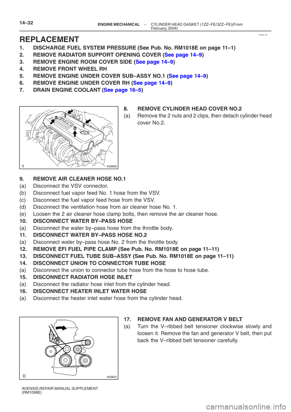
8. REMOVE CYLINDER HEAD COVER NO.2
(a) Remove the 2 nuts and 2 clips, then detach cylinder headcover No.2.
9. REMOVE AIR CLEANER HOSE NO.1
(a) Disconnect the VSV connector.
(b) Disconnect fuel vapor feed No. 1 hose from the VSV.
(c) Disconnect the fuel vapor feed hose from the VSV.
(d) Disconnect the ventilation hose from air cleaner hose No. 1.
(e) Loosen the 2 air cleaner hose clamp bolts, then remove the air cleaner h\
ose.
10. DISCONNECT WATER BY–PASS HOSE
(a) Disconnect the water by–pass hose from the throttle body.
11. DISCONNECT WATER BY–PASS HOSE NO.2
(a) Disconnect water by–pass hose No. 2 from the throttle body.
12. REMOVE EFI FUEL PIPE CLAMP (See Pub. No. RM1018E on page 11–11)
13. DISCONNECT FUEL TUBE SUB–ASSY (See Pub. No. RM1018E on page 11–11)
14. DISCONNECT UNION TO CONNECTOR TUBE HOSE
(a) Disconnect the union to connector tube hose from the hose to hose tube.
15. DISCONNECT RADIATOR HOSE INLET
(a) Disconnect the radiator hose inlet from the cylinder head.
16. DISCONNECT HEATER INLET WATER HOSE
(a) Disconnect the heater inlet water hose from the cylinder head. 17. REMOVE FAN AND GENERATOR V BELT
(a) Turn the V–ribbed belt tensioner clockwise slowly andloosen it. Remove the fan and generator V belt, then put
back the V–ribbed belt tensioner carefully.
Page 5066 of 5135
141UK–01
A784575 Claws
A78458
A78505
A78515
– ENGINE MECHANICALPARTIAL ENGINE ASSY (1ZZ–FE/3ZZ–FE)(From
February, 2004)14–9
AVENSIS REPAIR MANUAL SUPPLEMENT
(RM1098E)
REPLACEMENT
1. DISCHARGE FUEL SYSTEM PRESSURE (See Pub. No. RM1018E on page 11–1)
2. REMOVE RADIATOR SUPPORT OPENING COVER
(a) Remove the retainer and 4 clips.
(b) Unfasten the 5 claws, then remove the radiator support
opening cover.
3. REMOVE ENGINE ROOM COVER SIDE
(a) Remove the 2 clips and engine room cover side.
4. REMOVE FRONT WHEELS
5. REMOVE ENGINE UNDER COVER SUB–ASSY NO.1
(a) Remove the 5 clips, 2 screws and bolt, then detach the
engine under cover.
6. REMOVE ENGINE UNDER COVER LH
(a) Remove the 6 screws and 5 clips, then detach the engine
under cover.
Page 5067 of 5135
A78516
A93669
14–10–
ENGINE MECHANICAL PARTIAL ENGINE ASSY (1ZZ–FE/3ZZ–FE)(From
February, 2004)
AVENSIS REPAIR MANUAL SUPPLEMENT
(RM1098E)
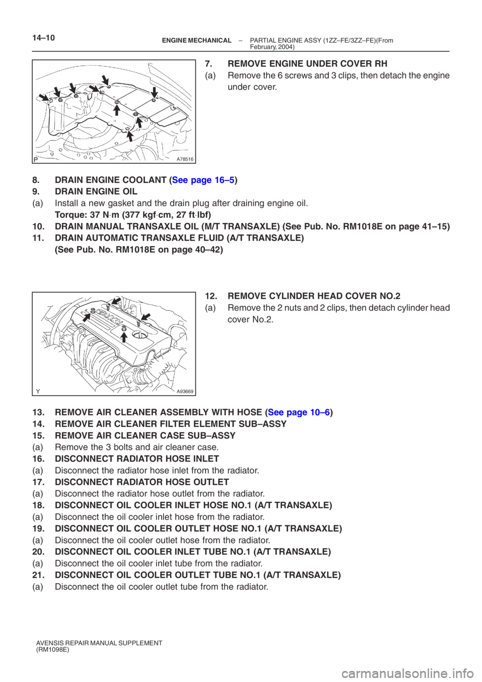
7. REMOVE ENGINE UNDER COVER RH
(a) Remove the 6 screws and 3 clips, then detach the engine under cover.
8. DRAIN ENGINE COOLANT (See page 16–5)
9. DRAIN ENGINE OIL
(a) Install a new gasket and the drain plug after draining engine oil.
Torque: 37 N ⋅m (377 kgf ⋅cm, 27 ft ⋅lbf)
10. DRAIN MANUAL TRANSAXLE OIL (M/T TRANSAXLE) (See Pub. No. RM1018E on p\
age 41–15)
11. DRAIN AUTOMATIC TRANSAXLE FLUID (A/T TRANSAXLE)
(See Pub. No. RM1018E on page 40–42)
12. REMOVE CYLINDER HEAD COVER NO.2
(a) Remove the 2 nuts and 2 clips, then detach cylinder head
cover No.2.
13. REMOVE AIR CLEANER ASSEMBLY WITH HOSE (See page 10–6)
14. REMOVE AIR CLEANER FILTER ELEMENT SUB–ASSY
15. REMOVE AIR CLEANER CASE SUB–ASSY
(a) Remove the 3 bolts and air cleaner case.
16. DISCONNECT RADIATOR HOSE INLET
(a) Disconnect the radiator hose inlet from the radiator.
17. DISCONNECT RADIATOR HOSE OUTLET
(a) Disconnect the radiator hose outlet from the radiator.
18. DISCONNECT OIL COOLER INLET HOSE NO.1 (A/T TRANSAXLE)
(a) Disconnect the oil cooler inlet hose from the radiator.
19. DISCONNECT OIL COOLER OUTLET HOSE NO.1 (A/T TRANSAXLE)
(a) Disconnect the oil cooler outlet hose from the radiator.
20. DISCONNECT OIL COOLER INLET TUBE NO.1 (A/T TRANSAXLE)
(a) Disconnect the oil cooler inlet tube from the radiator.
21. DISCONNECT OIL COOLER OUTLET TUBE NO.1 (A/T TRANSAXLE)
(a) Disconnect the oil cooler outlet tube from the radiator.
Page 5068 of 5135
A76724
A76714
A77338
– ENGINE MECHANICALPARTIAL ENGINE ASSY (1ZZ–FE/3ZZ–FE)(From
February, 2004)14–11
AVENSIS REPAIR MANUAL SUPPLEMENT
(RM1098E)
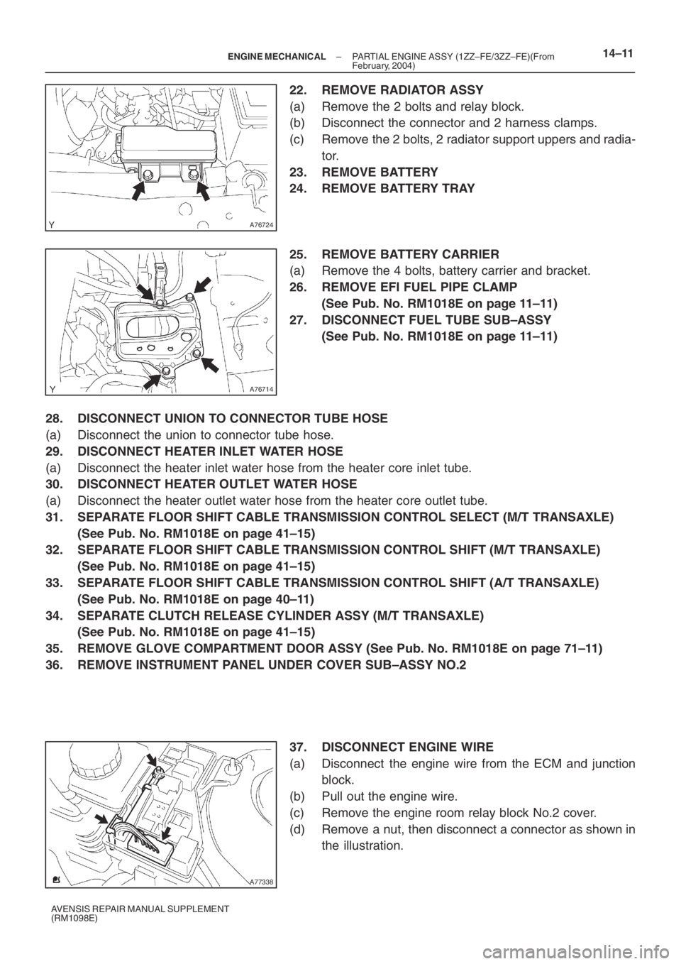
22. REMOVE RADIATOR ASSY
(a) Remove the 2 bolts and relay block.
(b) Disconnect the connector and 2 harness clamps.
(c) Remove the 2 bolts, 2 radiator support uppers and radia-
tor.
23. REMOVE BATTERY
24. REMOVE BATTERY TRAY
25. REMOVE BATTERY CARRIER
(a) Remove the 4 bolts, battery carrier and bracket.
26. REMOVE EFI FUEL PIPE CLAMP
(See Pub. No. RM1018E on page 11–11)
27. DISCONNECT FUEL TUBE SUB–ASSY
(See Pub. No. RM1018E on page 11–11)
28. DISCONNECT UNION TO CONNECTOR TUBE HOSE
(a) Disconnect the union to connector tube hose.
29. DISCONNECT HEATER INLET WATER HOSE
(a) Disconnect the heater inlet water hose from the heater core inlet tube.
30. DISCONNECT HEATER OUTLET WATER HOSE
(a) Disconnect the heater outlet water hose from the heater core outlet tube.
31. SEPARATE FLOOR SHIFT CABLE TRANSMISSION CONTROL SELECT (M/T TRANSAXLE)
(See Pub. No. RM1018E on page 41–15)
32. SEPARATE FLOOR SHIFT CABLE TRANSMISSION CONTROL SHIFT (M/T TRANSAXLE)
(See Pub. No. RM1018E on page 41–15)
33. SEPARATE FLOOR SHIFT CABLE TRANSMISSION CONTROL SHIFT (A/T TRANSAXLE)
(See Pub. No. RM1018E on page 40–11)
34. SEPARATE CLUTCH RELEASE CYLINDER ASSY (M/T TRANSAXLE)
(See Pub. No. RM1018E on page 41–15)
35. REMOVE GLOVE COMPARTMENT DOOR ASSY (See Pub. No. RM1018E on page 71–11)
36. REMOVE INSTRUMENT PANEL UNDER COVER SUB–ASSY NO.2
37. DISCONNECT ENGINE WIRE
(a) Disconnect the engine wire from the ECM and junction
block.
(b) Pull out the engine wire.
(c) Remove the engine room relay block No.2 cover.
(d) Remove a nut, then disconnect a connector as shown in
the illustration.
Page 5076 of 5135
A76723
A64033
A64034
A64034
A64033
– ENGINE MECHANICALPARTIAL ENGINE ASSY (1ZZ–FE/3ZZ–FE)(From
February, 2004)14–19
AVENSIS REPAIR MANUAL SUPPLEMENT
(RM1098E)
85. REMOVE EXHAUST MANIFOLD
(a) Remove the 5 nuts, then remove the exhaust manifold
and gasket.
86. REMOVE ENGINE COOLANT TEMPERATURE
SENSOR
(a) Using SST, remove the engine coolant temperature sen-
sor.
SST 09817–33190
87. REMOVE RADIO SETTING CONDENSER
(a) Remove the bolt and condenser.
88. REMOVE WATER BY–PASS HOSE NO.2
89. REMOVE RADIATOR HOSE INLET
90. REMOVE HEATER INLET WATER HOSE
91. REPLACE PARTIAL ENGINE ASSY
92. INSTALL RADIO SETTING CONDENSER
(a) Install the condenser with the bolt.
Torque: 10 N⋅m (102 kgf⋅cm, 7 ft⋅lbf)
93. INSTALL ENGINE COOLANT TEMPERATURE
SENSOR
(a) Install a new gasket onto the engine coolant temperature
sensor.
(b) Using SST, install the engine coolant temperature sensor.
SST 09817–33190
Torque: 20 N⋅m (204 kgf⋅cm, 15 ft⋅lbf)