Page 4133 of 5135

05 −24 1
AVENSIS Supplement (RM1045E)
FUEL PUMP CONTROL CIRCUIT
CIRCUIT DESCRIPTION
Refer to DTC P0230 on page 05 −141.
WIRING DIAGRAM
Refer")
1
2
3
4
A93906
−
DIAGNOSTICS SFI SYSTEM (2AZ−FSE)
05 −24 1
AVENSIS Supplement (RM1045E)
FUEL PUMP CONTROL CIRCUIT
CIRCUIT DESCRIPTION
Refer to DTC P0230 on page 05 −141.
WIRING DIAGRAM
Refer to DTC P0230 on page 05 −141.
INSPECTION PROCEDURE
1 CHECK FUEL PUMP OPERATION (See page 11− 4)
(a) Check if there is pressure in the fuel inlet hose.
HINT:
If there is fuel pressure, you will hear the sound of fuel flowing.
OK Go to step 9
NG
2 PERFORM ACTIVE TEST BY HAND −HELD TESTER(OPERATION OF CIRCUIT
OPENING RELAY)
(a) Connect the hand −held tester to the DLC3.
(b) Start the engine and warm it up.
(c) Turn the ignition switch to ON.
(d) Select the item: DIAGNOSIS / OBD/MOBD / ACTIVE TEST / FUEL PUMP/SPD.
(e) Check the relay operation when it is operated by the hand −held tester.
Standard: Operating sound can be heard from the relay.
OK Go to step 4
NG
3 INSPECT RADIATOR FAN RELAY
(a) Remove the R21 radiator fan relay.
(b) Check for continuity in the radiator fan relay relay. Standard:
Tester ConnectionSpecified Condition
1−2Continuity
3−4Continuity
1−2No Continuity
(Apply battery voltage to terminals 3 and 4)
(c) Reinstall the radiator fan relay relay.
NG REPLACE FUEL PUMP RELAY
OK
05HIS −01
Page 4135 of 5135

123
5
A79099Circuit Opening Relay Connector
Wire Harness Side:
C8
A83889
Wire Harness Side:
Front View R21
Radiator fun Relay Connector
A67586
Wire Harness Side:
Fuel Pump Connector F25
− DIAGNOSTICSSFI SYSTEM (2AZ−FSE)
05−243
AVENSIS Supplement (RM1045E)
6 CHECK HARNESS AND CONNECTOR(CIRCUIT OPENING RELY−RADIATOR FAN
RELAY, RADIATOR FAN RELAY−FUEL PUMP, FUEL PUMP−BODY GROUND)
(a) Check the harness and the connector between the circuit
opening relay and the radiator fan relay.
(1) Remove the C8 circuit opening relay.
(2) Remove the R21 radiator fan relay.
(3) Check the resistance between the wire harness
side connectors.
Standard (Check for open):
Tester ConnectionSpecified Condition
Circuit opening relay (C8−3)−Radiator fun relay (R21−2)Below 1�
Circuit opening relay (C8−3)−Radiator fun relay (R21−4)Below 1�
Standard (Check for short):
Tester ConnectionSpecified Condition
Circuit opening relay (C8−3) or Radiator fun relay (R21−2)
−Body ground10 k�or higher
Circuit opening relay (C8−3) or Radiator fun relay (R21−4)
−Body ground10 k�or higher
(4) Reinstall the circuit opening relay.
(5) Reinstall the radiator fan relay relay.
(b) Check the harness and the connector between the fuel
pump relay and the fuel pump.
(1) Remove the R21 radiator fan relay.
(2) Disconnect the F25 fuel pump connector.
(3) Check the resistance between the wire harness
side connectors.
Standard (Check for open):
Tester ConnectionSpecified Condition
Radiator fun relay (R21−1)−Fuel pump (F25−4)Below 1�
Standard (Check for short):
Tester ConnectionSpecified Condition
Radiator fun relay (R21−1) or Fuel pump (F25−4)
−Body ground10 k�or higher
(4) Reinstall the radiator fan relay.
(5) Disconnect the fuel pump connector.
(c) Check the harness and the connector between the fuel
pump relay and the body ground.
(1) Disconnect the F25 fuel pump connector.
(2) Check the resistance between the wire harness
side connector and body ground.
Standard (Check for open):
Tester ConnectionSpecified Condition
Fuel pump (F25−5)−Body groundBelow 1�
(3) Disconnect the fuel pump connector.
NG REPAIR OR REPLACE HARNESS OR
CONNECTOR
OK
Page 4140 of 5135
A83889
R21Radiator fun Relay Connector
Front View
Wire Harness Side:
A81695
E12
ECM Connector FPR
05−248
− DIAGNOSTICSSFI SYSTEM (2AZ−FSE)
AVENSIS Supplement (RM1045E)
14 CHECK HARNESS AND CONNECTOR(RADIATOR FAN RELAY−ECM)
(a) Check the harness and the connector between the radia-
tor fan relay and the ECM.
(1) Remove the R21 radiator fan relay.
(2) Disconnect the E12 ECM connector.
(3) Check the resistance between the wire harness
side connectors.
Standard (Check for open):
Tester ConnectionSpecified Condition
Radiator Fan relay (R21−3)−FPR (E12−7)Below 1�
Standard (Check for short):
Tester ConnectionSpecified Condition
Radiator Fan relay (R21−3) or FPR (E12−7)−Body ground10 k�or higher
(4) Reinstall the radiator fan relay.
(5) Reconnect the ECM connector.
NG REPAIR OR REPLACE HARNESS OR
CONNECTOR
OK
REPLACE ECM (See page10−65 of Pub. No. RM1018E AVENSIS)
Page 4464 of 5135
100LY−01
A84695
Mass Air Flow
Meter Connector
N·m (kgf·cm, ft·lbf) : Specified torqueEngine Cover Sub−assy
No. 1
9.0 (92, 80 in.�lbf)
VSV
Connector Fuel Vapor Feed
Hose
Clip
Engine Room Cover Side
Radiator Support Opening Cover
Clip
Retainer
x2
x4
1.5 (15, 13 in.�lbf)
Air Cleaner Filter
Element Sub−assy x2
Air Cleaner Cap
Sub−assy
− ENGINE CONTROL SYSTEMKNOCK SENSOR (2AZ−FSE)
10−11
AVENSIS Supplement (RM1045E)
KNOCK SENSOR (2AZ−FSE)
COMPONENTS
Page 4469 of 5135
100LX−01
A77897
(a)(a)
(a)
(a)
(b) 5 Claws
A77902
A78509
10 −8
−
ENGINE CONTROL SYSTEM THROTTLE BODY ASSY (2AZ−FSE)
AVENSIS Supplement (RM1045E)
REPLACEMENT
1. REMOVE RADIATOR SUPPORT OPENING COVER
(a) Remove the retainer and 4 clips.
(b) Unfasten the 5 claws, then remove the radiator support opening cover.
2. REMOVE ENGINE ROOM COVER SIDE
(a) Remove the 2 clips, then remove the engine room cover side.
3. DISCONNECT ENGINE WIRE NO.3 (BATTERY NEGATIVE TERMINAL)
4. DRAIN ENGINE COOLANT (See page 16 −7)
5. REMOVE ENGINE COVER SUB −ASSY NO.1
(a) Remove the 2 nuts, then remove the engine cover No. 1.
Page 4471 of 5135

(i)
10
−10
−
ENGINE CONTROL SYSTEM THROTTLE BODY ASSY (2AZ−FSE)
AVENSIS Supplement (RM1045E)
(h) Disconnect the water by −pass hose No. 1.
(i) Disconnect the water by −pass hose")
A78513
(h)
(i)
10
−10
−
ENGINE CONTROL SYSTEM THROTTLE BODY ASSY (2AZ−FSE)
AVENSIS Supplement (RM1045E)
(h) Disconnect the water by −pass hose No. 1.
(i) Disconnect the water by −pass hose No. 2.
8. INSTALL THROTTLE BODY ASSY
(a) Connect the water by −pass hose No. 2.
(b) Connect the water by −pass hose No. 1.
(c) Install a new gasket to the intake manifold.
(d) Install the throttle body with the 4 bolts. Torque: 9.0 N �m (90 kgf �cm, 80 in. �lbf)
(e) Install the throttle body bracket with the 4 bolts.
Torque: 21 N �m (210 kgf �cm, 15 ft �lbf)
(f) Install the ground terminal with the bolt.
Torque: 8.4 N �m (86 kgf �cm, 74 in. �lbf)
(g) Install the wiring harness protector with the clip.
(h) Tighten the bolt.
Torque: 8.4 N �m (86 kgf �cm, 74 in. �lbf)
(i) Connect the throttle control motor connector.
9. INSTALL AIR CLEANER CAP SUB −ASSY
Torque: 1.5 N �m (15 kgf �cm, 13 in. �lbf)
10. INSTALL ENGINE COVER SUB −ASSY NO.1
Torque: 9.0 N �m (92 kgf �cm, 80 in. �lbf)
11. CONNECT ENGINE WIRE NO.3 (BATTERY NEGATIVE TERMINAL) Torque: 5.4 N �m (55 kgf �cm, 48 in. �lbf)
12. ADD ENGINE COOLANT (See page 16 −7)
13. CHECK FOR ENGINE COOLANT LEAKS (See page 16 −1)
14. INSTALL ENGINE ROOM COVER SIDE
15. INSTALL RADIATOR SUPPORT OPENING COVER
Page 4472 of 5135
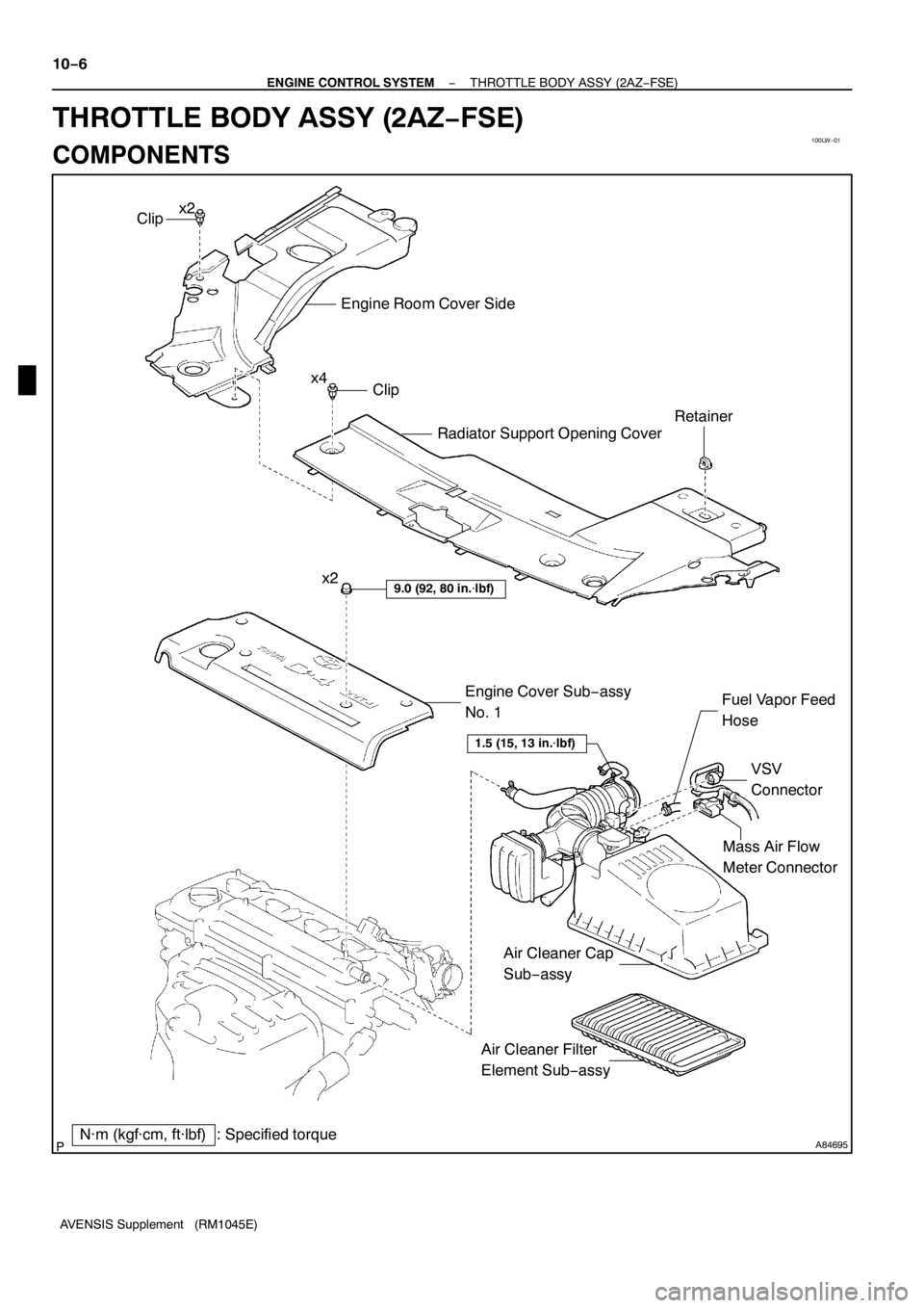
100LW−01
A84695
Mass Air Flow
Meter Connector
N·m (kgf·cm, ft·lbf) : Specified torqueEngine Cover Sub−assy
No. 1
9.0 (92, 80 in.�lbf)
VSV
Connector Fuel Vapor Feed
Hose
Clip
Engine Room Cover Side
Radiator Support Opening Cover
Clip
Retainer
x2
x4
1.5 (15, 13 in.�lbf)
Air Cleaner Filter
Element Sub−assy x2
Air Cleaner Cap
Sub−assy 10−6
− ENGINE CONTROL SYSTEMTHROTTLE BODY ASSY (2AZ−FSE)
AVENSIS Supplement (RM1045E)
THROTTLE BODY ASSY (2AZ−FSE)
COMPONENTS
Page 4554 of 5135
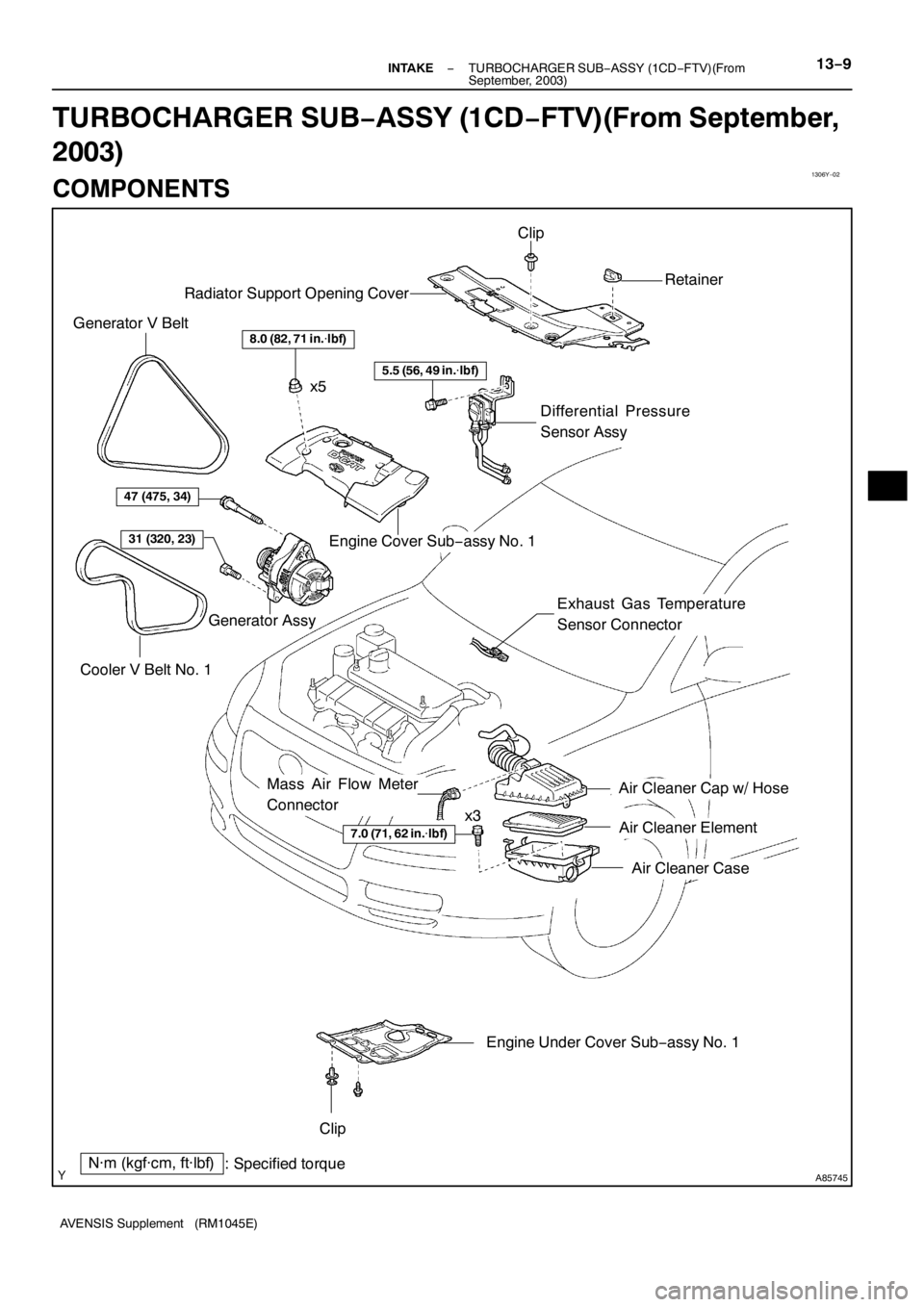
1306Y−02
A85745
8.0 (82, 71 in.�lbf)
Engine Cover Sub−assy No. 1 Radiator Support Opening Cover
N·m (kgf·cm, ft·lbf)
: Specified torque
7.0 (71, 62 in.�lbf)
Air Cleaner Cap w/ Hose
Air Cleaner Element
Air Cleaner Case
Engine Under Cover Sub−assy No. 1 Clip
Retainer
Clip
x5
x3 Cooler V Belt No. 1 Generator V Belt
Generator Assy
47 (475, 34)
31 (320, 23)
Differential Pressure
Sensor Assy
Exhaust Gas Temperature
Sensor Connector
5.5 (56, 49 in.�lbf)
Mass Air Flow Meter
Connector
− INTAKETURBOCHARGER SUB−ASSY (1CD−FTV)(From
September, 2003)13−9
AVENSIS Supplement (RM1045E)
TURBOCHARGER SUB−ASSY (1CD−FTV)(From September,
2003)
COMPONENTS

AVENSIS Supplement (RM1045E)
14 CHECK HARNESS AND CONNE")

(a)
(a)
(a)
(b) 5 Claws
A77902
A78509
10 −8
−
ENGINE CONTROL SYSTEM THROTTLE BODY ASSY (2AZ−FSE)
AVENSIS Supplement (RM1045E)
REPLACEMENT
1. REMOVE RADIATOR SUPPORT OPENING")