Page 2882 of 5135
D30364
Attachment
OUT
IN IN OUTAttachment
SST(s) SST(s)
Attachment
Attachment AZ Series:
1CD±FTV:
Z15498
Oil
Reservoir
PS Vane
Pump PS Gear
SST(s) Closed
Z15499
Oil
Reservoir
PS Vane
Pump PS Gear
SST(s) Open 51±6
± POWER STEERINGPOWER STEERING SYSTEM
AVENSIS REPAIR MANUAL (RM1018E)
(h) With the engine idling, close the valve of SST(s) and ob-
serve the reading on SST(s).
Minimum fluid pressure:
AZ Series:
8,300 to 9,000 kPa (85 to 92 kgf/cm
2, 1,204 to 1,305 psi)
1CD±FTV:
8,800 to 9,500 kPa (90 to 97 kgf/cm
2, 1,276 to 1,378 psi)
NOTICE:
�Do not keep the valve closed for more than 10 se-
conds.
�Do not let the fluid temperature become too high.
(i) With the engine idling, open the valve fully.
(j) Measure the fluid pressure at engine speeds of 1,000 rpm
and 3,000 rpm.
Fluid pressure difference:
490 kPa (5 kgf/cm
2, 71 psi) or less
NOTICE:
Do not turn the steering wheel.
Page 2883 of 5135

Open
Lock Position
F08858
±
POWER STEERING POWER STEERING SYSTEM
51±7
AVENSIS REPAIR MANUAL (RM1018E)
(k) With the engine idling and valve fully ope")
Z15500
Oil
ReservoirPS Vane
Pump
PS Gear
SST(s)
Open
Lock Position
F08858
±
POWER STEERING POWER STEERING SYSTEM
51±7
AVENSIS REPAIR MANUAL (RM1018E)
(k) With the engine idling and valve fully opened, turn the
steering wheel to full lock position.
Minimum fluid pressure:
AZ Series:
8,300 to 9,000 kPa (85 to 92 kgf/cm
2, 1,204 to 1,305 psi)
1CD±FTV:
8,800 to 9,500 kPa (90 to 97 kgf/cm
2, 1,276 to 1,378 psi)
NOTICE:
�Do not maintain lock position for more than 10 se-
conds.
�Do not let the fluid temperature become too high.
(l) Remove SST(s).
(m) AZ Series:
Connect the pressure feed tube assy to the vane pump
assy (See page 51±9).
(n) 1CD±FTV:
Connect the pressure feed tube assy to the vane pump
assy (See page 51±19).
(o) Bleed the power steering system.
5. CHECK STEERING EFFORT
(a) Center the steering wheel.
(b)Remove the steering wheel pad (See page 60±17).
(c) Start the engine and run it at idle.
(d) Measure the steering effort in both directions. Steering effort (Reference):
5.5 N´m (56 kgf´cm, 49 in.´lbf)
HINT:
Take the tire type, pressure and contact surface into consider-
ation before making your diagnosis.
(e) Torque the steering wheel set nut. Torque: 50 N´m (510 kgf´cm, 37 ft´lbf)
(f)Install the steering wheel pad (See page 60±17).
Page 2970 of 5135

SPIRAL CABLE SUB±ASSY
REPLACEMENT
HINT:
COMPONENTS: See page 60±16
1.PRE")
6009S±04
H42634
H42636 Claw
60±26
±
SUPPLEMENTAL RESTRAINT SYSTEM SPIRAL CABLE SUB±ASSY
AVENSIS REPAIR MANUAL (RM1018E)
SPIRAL CABLE SUB±ASSY
REPLACEMENT
HINT:
COMPONENTS: See page 60±16
1.PRECAUTION (See page 60±1)
2.DISCONNECT BATTERY NEGATIVE TERMINAL (See page 60±1)
3. PLACE FRONT WHEELS FACING STRAIGHT AHEAD
4.REMOVE HORN BUTTON ASSY (See page 60±17)
5.REMOVE STEERING WHEEL ASSY (See page 50±9) SST 09950±50013 (09951±05010, 09952±05010, 09953±05020, 09954±\
05021)
6.REMOVE INSTRUMENT PANEL HOLE COVER (See page 60±54)
7.REMOVE INSTRUMENT PANEL AIR BAG ASSY (See page 60±54)
8. REMOVE STEERING COLUMN COVER SUB±ASSYLOWER
(a) Remove the 3 screws and the steering column cover sub± assy lower.
9. REMOVE STEERING COLUMN COVER
W/INSTRUMENT CLUSTER FINISH PANEL ASSY
(a) Remove the steering column cover w/instrument cluster finish panel assy.
10. REMOVE SPIRAL CABLE SUB±ASSY
(a) Disconnect the airbag connector and the connector from the spiral cable sub±assy.
(b) Disengage the 3 claws and remove the spiral cable sub±
assy.
11.INSPECT SPIRAL CABLE SUB±ASSY (See page 60±11)
(a) If the following condition is identified, replace the spiral cable sub±\
assy with a new one. Condition:
Scratches or cracks on the connector
Cracks, dents or chips in the spiral cable sub±assy
12. PLACE FRONT WHEELS FACING STRAIGHT AHEAD
(a) Check that the front wheels are facing straight ahead.
Page 2971 of 5135

13. INSTALL SPIRAL CABLE SUB±ASSY
(a) Set the turn signal switch to the neutral pos")
H42637
H42638Marks
±
SUPPLEMENTAL RESTRAINT SYSTEM SPIRAL CABLE SUB±ASSY
60±27
AVENSIS REPAIR MANUAL (RM1018E)
13. INSTALL SPIRAL CABLE SUB±ASSY
(a) Set the turn signal switch to the neutral position.
NOTICE:
Make sure of the neutral position since the pin of the turn signal switc\
h may be snapped.
(b) Install the spiral cable sub±assy.
NOTICE:
When replacing the spiral cable sub±assy with a new one, remove the l\
ock pin before installing the
steering wheel assy.
(c) Connect the airbag connector and the connector.
(d) Install the steering column cover with the 3 screws.
14. ADJUST SPIRAL CABLE SUB±ASSY
(a) Check that the ignition switch is off.
(b) Check that the battery negative terminal is disconnected.
NOTICE:
Do not start the operation for 90 seconds after removing
the terminal.
(c) Turn the spiral cable sub±assy counterclockwise slowlyby hand until it feels firm.
(d) Then rotate the spiral cable sub±assy clockwise about 2.5 turns to align the marks.
HINT:
The spiral cable sub±assy will rotate about 2.5 turns to both left
and right of the center.
15.INSTALL STEERING COLUMN COVER SUB±ASSY LOWER (See page 50±9)
16.INSTALL INSTRUMENT PANEL AIR BAG ASSY (See page 60±54)
17.INSTALL STEERING WHEEL ASSY (See page 50±9)
18. INSPECT STEERING WHEEL CENTER POINT
19.INSTALL HORN BUTTON ASSY (See page 60±17)
20.INSPECT HORN BUTTON ASSY (See page 60±11)
21.INSPECT SRS WARNING LIGHT (See page 05±1184)
Page 2973 of 5135

H40006
SST(s)
H42625
H42626SST(s)
60±20
±
SUPPLEMENTAL RESTRAINT SYSTEM HORN BUTTON ASSY
AVENSIS REPAIR MANUAL (RM1018E)
(1) Connect the SST(s) to the battery. Connect the")
H40005
Battery
SST(s)
H40006
SST(s)
H42625
H42626SST(s)
60±20
±
SUPPLEMENTAL RESTRAINT SYSTEM HORN BUTTON ASSY
AVENSIS REPAIR MANUAL (RM1018E)
(1) Connect the SST(s) to the battery. Connect the red clip of the SST(s) to the battery
positive (+) terminal and the black clip of the SST(s)
to the battery negative (±) terminal.
HINT:
Do not connect the yellow connector of the SST(s) which is to
be connected with the supplemental restraint system.
(2) Check the function of the SST(s).Press the SST(s) activation switch, and check that
the LED of the SST(s) activation switch comes on.
CAUTION:
If the LED comes on when the activation switch is not being
pressed, SST(s) malfunction is posible, so be sure not to
use the SST(s). (3) Disconnect the SST(s) from the battery.
(b) Install the SST(s).
CAUTION:
Check that there is no looseness in the steering wheel assy
and horn button assy. (1)Remove the instrument panel hole (See page
60±54).
(2) Remove the instrument panel airbag assy (See page 60±54).
(3) While turning the steering wheel right and left, re-
move the 3 screws and steering column cover.
(4) Disconnect the airbag connector of the spiral cable sub±assy.
(5) Connect the connector of the SST(s) to the airbag connector of the spiral cable sub±assy.
SST 09082±00700, 09082±00780
NOTICE:
To avoid damaging the SST(s) connector and wire harness,
do not lock the secondary lock of the twin lock.
Page 2979 of 5135
6009P±04
H42622
H43002
±
SUPPLEMENTAL RESTRAINT SYSTEM HORN BUTTON ASSY
60±17
AVENSIS REPAIR MANUAL (RM1018E)
REPLACEMENT
1.PRECAUTION (See page 60±1)
2.DISCONNECT BATTERY NEGATIVE TERMINAL (See page 60±1)
3. REMOVE HORN BUTTON ASSY
(a) Place the front wheels facing straight ahead.
(b) Using a torx socket wrench (T30), loosen the 2 torxscrews until the groove along the screw circumference
catches on the screw case.
(c) Pull out the horn button assy from the steering wheel assy and support the horn button assy with one hand as shown
in the illustration.
NOTICE:
When removing the horn button assy, do not pull the airbag
wire harness.
(d) Using a screwdriver, disconnect the airbag connectors.
(e) Disconnect the horn connector.
(f) Remove the horn button assy.
Page 2980 of 5135
H43003
H42615
60±18
±
SUPPLEMENTAL RESTRAINT SYSTEM HORN BUTTON ASSY
AVENSIS REPAIR MANUAL (RM1018E)
4. INSTALL HORN BUTTON ASSY
(a) Support the horn button assy with the hand as shown in the illustration.
(b) Connect the airbag connectors.
(c) Connect the horn connector.
(d) Confirm that the circumference groove of the torx screw fits in the screw case, and place the horn button assy onto
the steering wheel assy.
(e) Using a torx socket wrench (T 30), install the 2 screws. Torque: 8.8 N �m (90 kgf �cm, 78 in. �lbf)
5.INSPECT HORN BUTTON ASSY (See page 60±11)
(a) Do a visual check which includes the following items with the horn button assy installed in the vehicle:
Cuts, minute cracks or marked discoloration on the horn
button assy top surface and in the grooved portion.
6.INSPECT SRS WARNING LIGHT (See page 05±1184)
Page 2981 of 5135
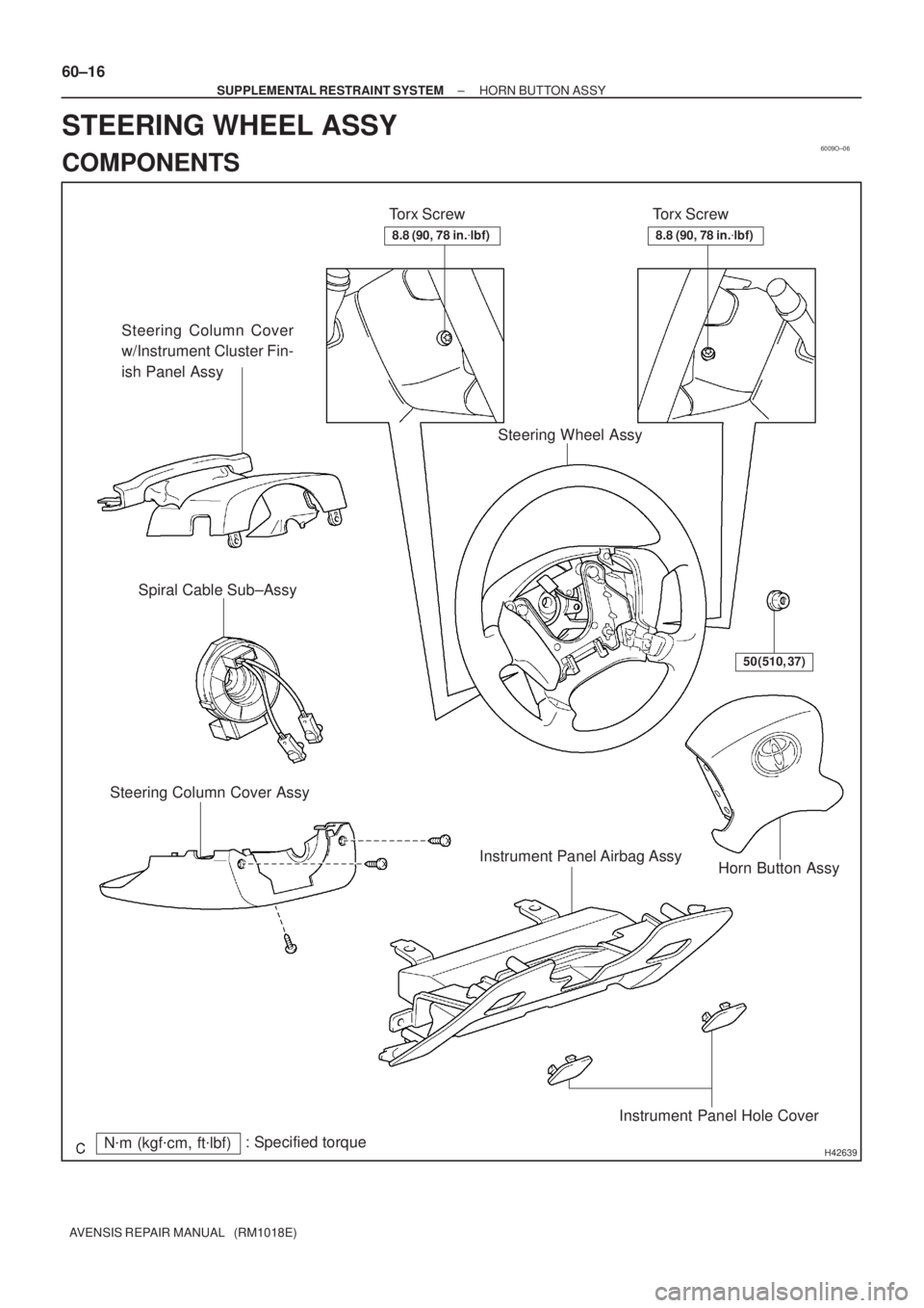
6009O±06
H42639N�m (kgf�cm, ft�lbf): Specified torqueTorx Screw
Steering Column Cover
w/Instrument Cluster Fin-
ish Panel Assy
Torx Screw
Horn Button Assy Steering Column Cover AssySpiral Cable Sub±Assy
Steering Wheel Assy
50 (510, 37)
Instrument Panel Airbag Assy
Instrument Panel Hole Cover
8.8 (90, 78 in.�lbf)8.8 (90, 78 in.�lbf)
60±16
± SUPPLEMENTAL RESTRAINT SYSTEMHORN BUTTON ASSY
AVENSIS REPAIR MANUAL (RM1018E)
STEERING WHEEL ASSY
COMPONENTS
 SST(s)
Attachment
Attachment AZ Series:
1CD±FTV:
Z15498
Oil
Reservoir
PS Vane
Pump PS Gear
SST(s) Closed
Z15499
Oil
Reservoir
PS Vane
Pump PS Gear
SST")

REPLACEMENT
1.PRECAUTION (See page 60±1)
2.DISCONNECT BATTERY NEGATIVE TERMINAL (See")

4. INSTALL HORN BUTTON ASSY
(a) Support the horn button assy with the hand as shown in the illu")